EP0368430B1 - A lubricator for a cylinder of an internal combustion engine - Google Patents
A lubricator for a cylinder of an internal combustion engine Download PDFInfo
- Publication number
- EP0368430B1 EP0368430B1 EP89250069A EP89250069A EP0368430B1 EP 0368430 B1 EP0368430 B1 EP 0368430B1 EP 89250069 A EP89250069 A EP 89250069A EP 89250069 A EP89250069 A EP 89250069A EP 0368430 B1 EP0368430 B1 EP 0368430B1
- Authority
- EP
- European Patent Office
- Prior art keywords
- lubrication
- cylinder
- lubricating
- accumulator
- lubricator
- Prior art date
- Legal status (The legal status is an assumption and is not a legal conclusion. Google has not performed a legal analysis and makes no representation as to the accuracy of the status listed.)
- Expired - Lifetime
Links
- 238000002485 combustion reaction Methods 0.000 title claims description 7
- 238000005461 lubrication Methods 0.000 claims description 48
- 230000001050 lubricating effect Effects 0.000 claims description 28
- 239000003921 oil Substances 0.000 claims description 25
- 239000010687 lubricating oil Substances 0.000 claims description 24
- 238000010586 diagram Methods 0.000 description 9
- 238000009825 accumulation Methods 0.000 description 4
- 238000000034 method Methods 0.000 description 2
- 230000006835 compression Effects 0.000 description 1
- 238000007906 compression Methods 0.000 description 1
- 238000007599 discharging Methods 0.000 description 1
- 238000004880 explosion Methods 0.000 description 1
- 238000005457 optimization Methods 0.000 description 1
- 230000000630 rising effect Effects 0.000 description 1
Images


Classifications
-
- F—MECHANICAL ENGINEERING; LIGHTING; HEATING; WEAPONS; BLASTING
- F01—MACHINES OR ENGINES IN GENERAL; ENGINE PLANTS IN GENERAL; STEAM ENGINES
- F01M—LUBRICATING OF MACHINES OR ENGINES IN GENERAL; LUBRICATING INTERNAL COMBUSTION ENGINES; CRANKCASE VENTILATING
- F01M1/00—Pressure lubrication
- F01M1/16—Controlling lubricant pressure or quantity
-
- F—MECHANICAL ENGINEERING; LIGHTING; HEATING; WEAPONS; BLASTING
- F01—MACHINES OR ENGINES IN GENERAL; ENGINE PLANTS IN GENERAL; STEAM ENGINES
- F01M—LUBRICATING OF MACHINES OR ENGINES IN GENERAL; LUBRICATING INTERNAL COMBUSTION ENGINES; CRANKCASE VENTILATING
- F01M1/00—Pressure lubrication
- F01M1/14—Timed lubrication
-
- F—MECHANICAL ENGINEERING; LIGHTING; HEATING; WEAPONS; BLASTING
- F16—ENGINEERING ELEMENTS AND UNITS; GENERAL MEASURES FOR PRODUCING AND MAINTAINING EFFECTIVE FUNCTIONING OF MACHINES OR INSTALLATIONS; THERMAL INSULATION IN GENERAL
- F16N—LUBRICATING
- F16N13/00—Lubricating-pumps
- F16N13/02—Lubricating-pumps with reciprocating piston
- F16N13/06—Actuation of lubricating-pumps
- F16N13/16—Actuation of lubricating-pumps with fluid drive
-
- F—MECHANICAL ENGINEERING; LIGHTING; HEATING; WEAPONS; BLASTING
- F16—ENGINEERING ELEMENTS AND UNITS; GENERAL MEASURES FOR PRODUCING AND MAINTAINING EFFECTIVE FUNCTIONING OF MACHINES OR INSTALLATIONS; THERMAL INSULATION IN GENERAL
- F16N—LUBRICATING
- F16N29/00—Special means in lubricating arrangements or systems providing for the indication or detection of undesired conditions; Use of devices responsive to conditions in lubricating arrangements or systems
- F16N29/04—Special means in lubricating arrangements or systems providing for the indication or detection of undesired conditions; Use of devices responsive to conditions in lubricating arrangements or systems enabling a warning to be given; enabling moving parts to be stopped
-
- F—MECHANICAL ENGINEERING; LIGHTING; HEATING; WEAPONS; BLASTING
- F01—MACHINES OR ENGINES IN GENERAL; ENGINE PLANTS IN GENERAL; STEAM ENGINES
- F01M—LUBRICATING OF MACHINES OR ENGINES IN GENERAL; LUBRICATING INTERNAL COMBUSTION ENGINES; CRANKCASE VENTILATING
- F01M1/00—Pressure lubrication
- F01M1/02—Pressure lubrication using lubricating pumps
- F01M2001/0207—Pressure lubrication using lubricating pumps characterised by the type of pump
- F01M2001/0215—Electrical pumps
-
- F—MECHANICAL ENGINEERING; LIGHTING; HEATING; WEAPONS; BLASTING
- F01—MACHINES OR ENGINES IN GENERAL; ENGINE PLANTS IN GENERAL; STEAM ENGINES
- F01M—LUBRICATING OF MACHINES OR ENGINES IN GENERAL; LUBRICATING INTERNAL COMBUSTION ENGINES; CRANKCASE VENTILATING
- F01M1/00—Pressure lubrication
- F01M1/08—Lubricating systems characterised by the provision therein of lubricant jetting means
- F01M2001/083—Lubricating systems characterised by the provision therein of lubricant jetting means for lubricating cylinders
-
- F—MECHANICAL ENGINEERING; LIGHTING; HEATING; WEAPONS; BLASTING
- F16—ENGINEERING ELEMENTS AND UNITS; GENERAL MEASURES FOR PRODUCING AND MAINTAINING EFFECTIVE FUNCTIONING OF MACHINES OR INSTALLATIONS; THERMAL INSULATION IN GENERAL
- F16N—LUBRICATING
- F16N2250/00—Measuring
- F16N2250/04—Pressure
- F16N2250/06—Pressure for determining flow
-
- F—MECHANICAL ENGINEERING; LIGHTING; HEATING; WEAPONS; BLASTING
- F16—ENGINEERING ELEMENTS AND UNITS; GENERAL MEASURES FOR PRODUCING AND MAINTAINING EFFECTIVE FUNCTIONING OF MACHINES OR INSTALLATIONS; THERMAL INSULATION IN GENERAL
- F16N—LUBRICATING
- F16N2270/00—Controlling
- F16N2270/20—Amount of lubricant
- F16N2270/30—Amount of lubricant intermittent
Definitions
- the present invention relates to an internal combustion engine, and more particularly to a lubricator for a cylinder of a large-sized diesel engine.
- lubricating oil is forcedly poured through a lubricating opening formed in the cylinder liner.
- Fig. 10 illustrates a lubricator for a cylinder liner of a diesel engine for a ship.
- numeral 1a denotes a piston, 2a a cylinder liner in which the piston 1a is slidably reciprocated, 3a a lubricating rod mounted to the cylinder liner 2a externally and in which a check valve is contained, and 7a a lubricating pipe connecting a lubricating device 9a and the lubricating rod 3a.
- a plurality of plunger pumps are assembled in the lubricating device 9a in order to forcedly feed oil into a plurality of lubricating openings formed in the cylinder liner 2a. Plungers of the plunger pump are driven by a cam (not shown) provided therein.
- Numeral 10a denotes a drive shaft to which the cam is mounted and which is driven through a gear or chain by a crank shaft to feed oil at a periodical timing of a crank angle.
- the cam in the lubricating device 9a pushes up the plunger and the pressurized oil reaches the lubricating rod through the lubricating pipe 7a to open the check valve so that the oil is fed into the cylinder liner 2a through the lubricating openings.
- ⁇ d is a discharge period of the plunger, and the discharge is completed at a time ⁇ before the top dead center (TDC) where the piston 1a passes through the lubricating opening.
- TDC top dead center
- the conventional lubricator drives the plunger in response to rotation of the cam interlocked with the crank shaft to feed oil for lubrication, it is not possible to change the lubricating time in response to an engine operation condition in order to attain effective lubrication. Further, it is necessary to feed a more amount of oil as compared with a necessary amount in order to prevent the failure of lubrication.
- the DE-A-2929 580 describes a lubricator for a cylinder of an internal combustion engine comprising an electric motor for forcedly feeding lubricating oil in an oil tank to an accumulator, one or more control valves for feeding the lubricating oil in the accumulator to the cylinder, a pressure detector for detecting a pressure of the lubricating oil in the accumulator and a controller for supplying a drive command to the electric pump so tha the pressure of the lubricating oil in the accumulator is equal to a predetermined value on the basis of a lubricating condition, an operation condition and a signal of the pressure detector, and for deriving one or more end-of-lubrication timings on the basis of the lubricating condition, the operation condition and one or more established start-of-lubrication timings to supply to the control valve with a valve opening command when a crank angle is coincident with the start-of-lubrication timing and with a valve closing command when the crank angle is coincident with the
- the lubricator for a cylinder of an internal combustion engine comprising a plurality of accumulators for holding lubricating oil fed from an oil tank by a pump to a predetermined pressure, a solenoid controlled valve disposed between the pump and the accumulator, one or more control valves for feeding the lubricating oil in the accumulator to the cylinder, and a controller for selecting an accumulator to be used on the basis of a lubrication condition and an operation condition to supply a switching command to the solenoid controlled valve and deriving one or more end-of-lubrication timings on the basis of the lubrication condition, the operation condition and one or more established start-of-lubrication timings to supply to the control valve with a valve opening command when the crank angle is coincident with the start-of-lubrication timing and with a valve closing command when the crank angle is coincident with the end-of-lubrication timing.
- the lubrication timing and the amount of lubricating oil are controlled independently and the cylinder liner and the piston ring are lubricated in the optimum condition corresponding to the operation condition of the engine.
- the system is different from a conventional lubricator in that lubricating oil is accumulated and an electro hydraulic control valve is disposed between an accumulation rod and a distributor and is driven by an output of a controller which calculates an optimum lubrication timing and an amount of lubrication oil on the basis of the operation condition of the engine separately so that control is automatically performed to be identical with a target condition.
- the accumulation type cylinder lubrication control system can control a timing of discharging lubricating oil from the lubrication rod, that is, the lubrication timing in synchronism with any crank angle in one cycle of the piston and accordingly lubrication corresponding to lubrication before a top ring, between rings and before a bottom ring can be effected with a high speed response.
- an opening of the control valve and a pressure of the accumulated oil can be selectively controlled to control an amount of oil lubricated at a time freely.
- the lubrication timing and the amount of lubricating oil can be controlled automatically so that wear of the piston ring and the cylinder liner can be minimized and the amount of consumption of expensive lubrication oil for the cylinder can be reduced.
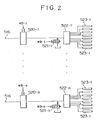
- numeral 501 denotes an oil pressure pump, 502 a strainer, 503 a reservoir, 504 a relief valve, 505 a high pressure filter, 506 a cheek valve, 507 an electric motor or a cam shaft, 508 a controller, 509 a change-over solenoid controlled valve, 510-1 to 510-k change-over solenoid controlled valves for accumulators (k indicates a number of levels of accumulation), 511-1 to 511-k accumulators, 512-1 to 512-k oil pressure detectors, 513-1 to 513-k gas detectors, 514-1 to 514-k main valves, 515-1 to 515-k check valves, 516 a discharge port, 520 an electro hydraulic control valve, 521 a bypass valve, 522 a lubricating oil distribution valve, and 523 a lubricating rod.
- an amount of lubricating oil Q corresponding to a load L of the engine, a pressure P Z in the cylinder (refer to Fig. 9(a)), set pressures P sh for the accumulators 511-k (set stepwise), an effective differential pressure P L , and a correction angle ⁇ ⁇ s and ⁇ ⁇ e (previously obtained discharge delay from the electro hydraulic control valve 20 to the lubricating rod 23) are supplied to the controller 508 and are stored.
- oil pressure values are supplied from the oil pressure detectors 512-k of the accumulators 511-k to the controller, which compares each of the oil pressure values with each of the set values, respectively.
- the solenoid controlled valve 509 is switched to the accumulator 511-k (*1) and the discharge amount is changed to the oil pressure pump 501 (a swash plate angle is driven) to charge the set value.
- the controller When the engine begins to operate and the number of rotation n and the crank angle ⁇ are supplied to the controller, the controller reads the pressure P Z in the cylinder corresponding to the number of rotation n and selects the minimum accumulator 511-k set to P sk ⁇ P Z +P L so that the main valve 514-k corresponding to this accumulator 511-k is opened and the solenoid controlled valve 509 is switched to this accumulator 511-k (*1).
- the controller 508 when the start-of-lubrication target timing ⁇ s is supplied to the controller 508, the controller performs the following calculation and derives the end-of-lubrication target timing ⁇ e.
- ⁇ e ⁇ s + 6nQ (A ⁇ (2g(Psi - Pz)/ ⁇ ) 1/2 )
- Figs. 6 to 8 are flow charts showing the above operations, in which Fig. 6 is a flow chart corresponding to a configuration of Fig. 2, Fig. 7 is a flow chart corresponding to a configuration of Fig. 3, and Fig. 8 is a flow chart corresponding to a configuration of Fig. 5.
- Suffixes j, k, n, i and r are a lubrication timing in one cycle, a number of accumulators, a total number of cylinders, the number of cylinder and the element number.
- the electro hydraulic control valve 520 is opened, the lubricating oil having the amount Q set to the optimum is fed to the accumulator 511, the main valve 514, the electro hydraulic control valve 520 (distribution valve 522), the lubricating rod 523 and the cylinder in this order of the description.
- Figs. 9(b), (c) and (d) show the case where the lubrication is made once, twice and four times in one cycle. It is apparent from the drawing that the lubrication can be made even if the lubrication timing is set to any time when a plurality of lubrications are made in one cycle since various pressures are set to the accumulators 511.
- the bypass command is supplied to the controller 508 prior to the operation of the engine so that the bypass valve 521 is opened (*9) and the lubricating oil can be circulated until the temperature of the oil becomes a proper temperature.
- the controller 508 is supplied with detected values of the gas pressure detector 513 and the oil pressure detector 512 and when the gas pressure is smaller than the oil pressure, the controller opens the solenoid controlled valve 10 in order to protect a plug (made of rubber) in the accumulator (*2 - *4). Further, when the gas pressure is equal to substantially zero, it is determined as leakage of gas or explosion of the plug and an alarm is sent to the outside.
Landscapes
- Engineering & Computer Science (AREA)
- General Engineering & Computer Science (AREA)
- Mechanical Engineering (AREA)
- Lubrication Of Internal Combustion Engines (AREA)
Applications Claiming Priority (4)
| Application Number | Priority Date | Filing Date | Title |
|---|---|---|---|
| JP27458688 | 1988-11-01 | ||
| JP274586/88 | 1988-11-01 | ||
| JP28247588 | 1988-11-10 | ||
| JP282475/88 | 1988-11-10 |
Publications (3)
| Publication Number | Publication Date |
|---|---|
| EP0368430A2 EP0368430A2 (en) | 1990-05-16 |
| EP0368430A3 EP0368430A3 (en) | 1990-06-20 |
| EP0368430B1 true EP0368430B1 (en) | 1994-03-16 |
Family
ID=26551090
Family Applications (1)
| Application Number | Title | Priority Date | Filing Date |
|---|---|---|---|
| EP89250069A Expired - Lifetime EP0368430B1 (en) | 1988-11-01 | 1989-10-31 | A lubricator for a cylinder of an internal combustion engine |
Country Status (4)
| Country | Link |
|---|---|
| EP (1) | EP0368430B1 (da) |
| KR (1) | KR930004767B1 (da) |
| DE (1) | DE68913910T2 (da) |
| DK (1) | DK171974B1 (da) |
Cited By (1)
| Publication number | Priority date | Publication date | Assignee | Title |
|---|---|---|---|---|
| US12269729B2 (en) | 2023-01-27 | 2025-04-08 | Vgp Ipco Llc | Reusable or refillable container for dispensing motor oil |
Families Citing this family (18)
| Publication number | Priority date | Publication date | Assignee | Title |
|---|---|---|---|---|
| JPH04318253A (ja) * | 1991-04-18 | 1992-11-09 | Mitsubishi Heavy Ind Ltd | 多気筒エンジン |
| JPH08118967A (ja) * | 1994-10-27 | 1996-05-14 | Yamaha Motor Co Ltd | エンジンの車載構造 |
| JP3709957B2 (ja) * | 1997-12-03 | 2005-10-26 | 本田技研工業株式会社 | 車両用エンジンの潤滑装置 |
| CA2350105A1 (en) * | 1998-11-05 | 2000-05-18 | Hans Jensen Lubricators A/S | Lubrication system for large diesel engines |
| DE10221735A1 (de) | 2002-05-16 | 2003-12-24 | Deere & Co | Gutaufnahmevorrichtung und Höhenführungsvorrichtung |
| JP3806398B2 (ja) * | 2002-11-28 | 2006-08-09 | 三菱重工業株式会社 | シリンダ注油装置 |
| FR2857693A1 (fr) * | 2003-07-15 | 2005-01-21 | Paul Rene Guidone | Dispositif de lubrification complementaire et de securite au circuit traditionnel de lubrification d'une machine ou d'un moteur |
| KR100750542B1 (ko) * | 2004-03-31 | 2007-08-20 | 미츠비시 쥬고교 가부시키가이샤 | 실린더 윤활 시스템을 구비한 내연기관 |
| JP4031772B2 (ja) * | 2004-04-16 | 2008-01-09 | 三菱重工業株式会社 | シリンダ注油装置を備えた内燃機関 |
| DK176742B1 (da) * | 2004-06-30 | 2009-06-02 | Hans Jensen Lubricators As | Fremgangsmåde og apparat til smöring af cylinderfladerne i store dieselmotorer |
| KR20090089789A (ko) * | 2008-02-19 | 2009-08-24 | 베르트질레 슈바이츠 악티엔게젤샤프트 | 실린더 윤활용 장치 |
| DK2177720T3 (da) * | 2008-10-16 | 2014-06-30 | Wärtsilä Schweiz AG | Stor dieselmotor |
| DK177746B1 (da) | 2009-06-23 | 2014-05-26 | Hans Jensen Lubricators As | Fremgangsmåde til cylindersmøring af store dieselmotorer såsom skibsmotorer |
| DK177056B1 (da) * | 2010-03-12 | 2011-04-11 | Hans Jensen Lubricators As | Ventilarrangement samt fremgangsmåde til drift af sådan ventilarrangement |
| EP2395208A1 (de) * | 2010-06-11 | 2011-12-14 | Wärtsilä Schweiz AG | Grossmotor mit einer Zylinderschmiervorrichtung und Verfahren zur Schmierung eines Zylinders eines Grossmotors |
| EP2930414B1 (en) * | 2014-04-11 | 2019-10-09 | Alfa Laval Corporate AB | Lubrication control system |
| SG11201802914XA (en) * | 2015-10-28 | 2018-05-30 | Hans Jensen Lubricators As | A large slow-running two-stroke engine with sip lubricant injector |
| DE102016116085A1 (de) * | 2016-08-30 | 2018-03-01 | Gebr. Heller Maschinenfabrik Gmbh | Drehtischlager-Schmiervorrichtung und Verfahren zur Schmierung eines Drehtisch-Wälzlagers |
Family Cites Families (4)
| Publication number | Priority date | Publication date | Assignee | Title |
|---|---|---|---|---|
| CH613495A5 (en) * | 1976-04-15 | 1979-09-28 | Sulzer Ag | Cylinder lubrication device for a piston internal combustion engine |
| DE2827626A1 (de) * | 1978-04-24 | 1979-10-25 | Burmeister & Wains As | Verfahren beim schmieren der zylinderlaufflaechen einer kolbenmaschine und schmiersystem zur ausuebung dieses verfahrens |
| DE2929580A1 (de) * | 1979-07-21 | 1981-02-05 | Mm A N Maschinenfabrik Augsbur | Schmiersystem fuer eine brennkraftmaschine |
| GR75371B (da) * | 1980-10-04 | 1984-07-13 | British Petroleum Co |
-
1989
- 1989-10-23 DK DK524589A patent/DK171974B1/da not_active IP Right Cessation
- 1989-10-31 EP EP89250069A patent/EP0368430B1/en not_active Expired - Lifetime
- 1989-10-31 DE DE68913910T patent/DE68913910T2/de not_active Expired - Fee Related
- 1989-11-01 KR KR1019890015806A patent/KR930004767B1/ko not_active Expired - Fee Related
Cited By (1)
| Publication number | Priority date | Publication date | Assignee | Title |
|---|---|---|---|---|
| US12269729B2 (en) | 2023-01-27 | 2025-04-08 | Vgp Ipco Llc | Reusable or refillable container for dispensing motor oil |
Also Published As
| Publication number | Publication date |
|---|---|
| DK171974B1 (da) | 1997-09-01 |
| DK524589A (da) | 1990-05-02 |
| DK524589D0 (da) | 1989-10-23 |
| DE68913910T2 (de) | 1994-06-23 |
| DE68913910D1 (de) | 1994-04-21 |
| KR930004767B1 (ko) | 1993-06-05 |
| EP0368430A2 (en) | 1990-05-16 |
| KR900008148A (ko) | 1990-06-02 |
| EP0368430A3 (en) | 1990-06-20 |
Similar Documents
| Publication | Publication Date | Title |
|---|---|---|
| EP0368430B1 (en) | A lubricator for a cylinder of an internal combustion engine | |
| EP0629777B1 (en) | Fuel injection system | |
| EP0494220B1 (en) | A variable compression ratio internal combustion engine | |
| US6669453B1 (en) | Pump assembly useful in internal combustion engines | |
| US5417185A (en) | Variable compression piston | |
| KR100411834B1 (ko) | 멀티실린더 내연기관용 실린더 윤활시스템 | |
| EP1285164B1 (en) | Pump assembly and method for controlling outlet pressure | |
| US5363816A (en) | Valve drive device | |
| US3633552A (en) | Internal combustion engine including maximum firing pressure-limiting means | |
| EP0091862A1 (en) | Double dump single solenoid unit injector | |
| US5178103A (en) | Variable compression ratio piston | |
| US5263441A (en) | Hydraulic valve control apparatus for internal combustion engines | |
| WO1994029577A1 (en) | A large two-stroke internal combustion engine | |
| KR890002578B1 (ko) | 왕복운동 내연기관용 배기밸브 | |
| EP1076180B1 (en) | Fuel pump | |
| US5247911A (en) | Compression ratio control in gasoline engines | |
| NO135039B (da) | ||
| US6736091B1 (en) | Variable compression ratio control system for internal combustion engine | |
| JP2001526755A (ja) | 内燃機関用の液圧作動式燃料ポンプの作動方法及び該液圧作動式燃料ポンプ | |
| JP2002508047A (ja) | 火花点火機関用直接燃料注入ポンプおよび同ポンプを有する注入システム | |
| US4431381A (en) | Variable volume hydraulic pump | |
| US3294075A (en) | Injection system for internal combustion engines | |
| JP2659828B2 (ja) | 内燃機関のシリンダ注油装置 | |
| SU821719A1 (ru) | Система регулировани свободнопоршневогодВигАТЕл | |
| US12326142B2 (en) | Diaphragm position control system |
Legal Events
| Date | Code | Title | Description |
|---|---|---|---|
| PUAI | Public reference made under article 153(3) epc to a published international application that has entered the european phase |
Free format text: ORIGINAL CODE: 0009012 |
|
| PUAL | Search report despatched |
Free format text: ORIGINAL CODE: 0009013 |
|
| AK | Designated contracting states |
Kind code of ref document: A2 Designated state(s): CH DE LI |
|
| AK | Designated contracting states |
Kind code of ref document: A3 Designated state(s): CH DE LI |
|
| 17P | Request for examination filed |
Effective date: 19900829 |
|
| 17Q | First examination report despatched |
Effective date: 19911104 |
|
| GRAA | (expected) grant |
Free format text: ORIGINAL CODE: 0009210 |
|
| AK | Designated contracting states |
Kind code of ref document: B1 Designated state(s): CH DE LI |
|
| REF | Corresponds to: |
Ref document number: 68913910 Country of ref document: DE Date of ref document: 19940421 |
|
| PLBE | No opposition filed within time limit |
Free format text: ORIGINAL CODE: 0009261 |
|
| STAA | Information on the status of an ep patent application or granted ep patent |
Free format text: STATUS: NO OPPOSITION FILED WITHIN TIME LIMIT |
|
| 26N | No opposition filed | ||
| PGFP | Annual fee paid to national office [announced via postgrant information from national office to epo] |
Ref country code: CH Payment date: 19961121 Year of fee payment: 8 |
|
| PG25 | Lapsed in a contracting state [announced via postgrant information from national office to epo] |
Ref country code: LI Free format text: LAPSE BECAUSE OF NON-PAYMENT OF DUE FEES Effective date: 19971031 Ref country code: CH Free format text: LAPSE BECAUSE OF NON-PAYMENT OF DUE FEES Effective date: 19971031 |
|
| PGFP | Annual fee paid to national office [announced via postgrant information from national office to epo] |
Ref country code: DE Payment date: 19971110 Year of fee payment: 9 |
|
| REG | Reference to a national code |
Ref country code: CH Ref legal event code: PL |
|
| PG25 | Lapsed in a contracting state [announced via postgrant information from national office to epo] |
Ref country code: DE Free format text: LAPSE BECAUSE OF NON-PAYMENT OF DUE FEES Effective date: 19990803 |