EP0368440B1 - Source sismique vibratoire - Google Patents
Source sismique vibratoire Download PDFInfo
- Publication number
- EP0368440B1 EP0368440B1 EP89306512A EP89306512A EP0368440B1 EP 0368440 B1 EP0368440 B1 EP 0368440B1 EP 89306512 A EP89306512 A EP 89306512A EP 89306512 A EP89306512 A EP 89306512A EP 0368440 B1 EP0368440 B1 EP 0368440B1
- Authority
- EP
- European Patent Office
- Prior art keywords
- vibratory
- base plate
- lift
- variable length
- frame
- Prior art date
- Legal status (The legal status is an assumption and is not a legal conclusion. Google has not performed a legal analysis and makes no representation as to the accuracy of the status listed.)
- Expired
Links
- 230000033001 locomotion Effects 0.000 claims description 11
- 230000035939 shock Effects 0.000 claims description 7
- 238000013016 damping Methods 0.000 claims description 4
- 230000004044 response Effects 0.000 claims description 3
- 230000008859 change Effects 0.000 claims description 2
- 239000004020 conductor Substances 0.000 description 6
- 230000015572 biosynthetic process Effects 0.000 description 5
- 239000012530 fluid Substances 0.000 description 5
- 230000008878 coupling Effects 0.000 description 4
- 238000010168 coupling process Methods 0.000 description 4
- 238000005859 coupling reaction Methods 0.000 description 4
- 239000003643 water by type Substances 0.000 description 4
- 230000000694 effects Effects 0.000 description 2
- 239000011148 porous material Substances 0.000 description 2
- 239000011435 rock Substances 0.000 description 2
- 230000005540 biological transmission Effects 0.000 description 1
- 238000010586 diagram Methods 0.000 description 1
- 230000006872 improvement Effects 0.000 description 1
- 238000002955 isolation Methods 0.000 description 1
- 238000004519 manufacturing process Methods 0.000 description 1
- 238000000034 method Methods 0.000 description 1
- 238000012986 modification Methods 0.000 description 1
- 230000004048 modification Effects 0.000 description 1
- 239000012858 resilient material Substances 0.000 description 1
- 230000000284 resting effect Effects 0.000 description 1
Images

Classifications
-
- G—PHYSICS
- G01—MEASURING; TESTING
- G01V—GEOPHYSICS; GRAVITATIONAL MEASUREMENTS; DETECTING MASSES OR OBJECTS; TAGS
- G01V1/00—Seismology; Seismic or acoustic prospecting or detecting
- G01V1/02—Generating seismic energy
- G01V1/04—Details
- G01V1/047—Arrangements for coupling the generator to the ground
- G01V1/053—Arrangements for coupling the generator to the ground for generating transverse waves
Definitions
- This invention relates generally to apparatus for imparting seismic vibratory signals to the earth. More particularly, but not by way of limitation, this invention relates to improved apparatus for imparting seismic vibratory signals to the earth along a selected vector path.
- Vp/Vs compressional to shear wave velocity ratio
- the referenced Waters patent teaches that the parallel planes in which the respective vibration axes of the two masses lie are to be oriented either transversely to the line of seismic survey, i.e., the line between the location of the seismic source and the recording geophones, or along such survey line. With proper phasing, the above-referenced transverse axial orientation of the vibrating masses enables one to produce and record simultaneously P waves and shear SH waves. On the other hand, if the vibrational axes are aligned with the survey line, one can generate and record simultaneously P waves and shear SV waves. The vertical component of motion in both cases produces so called "converted" shear SV waves and shear SV waves, but such waves cannot be processed and interpreted with conventional seismic methods. Thus, Waters teaches in effect that only by operating the patented apparatus successively in these two modes can one generate and record at a single remote location all forms of a seismic wave, including P, SH and SV waves, in a manner which permits conventional processing.
- Patents illustrating full wave field vibratory seismic sources include U.S. Patent No, 4,662,473, issued May 5, 1987, to Robert M. Betz; U.S. Patent No. 4,655,314 issued April 7, 1987, to Tom P, Airhart; U.S. Patent No. 4,660,675, issued April 28, 1987, to Tom P. Airhart; and U.S. Patent No. 4,719,607 issued January 12, 1988 to Tom P. Airhart.
- Each of these patens illustrate apparatus capable of producing vibratory seismic waves at varying inclinations and azimuths without repositioning the ground engaging base plate of the apparatus or without repositioning the vehicle utilized for carrying such apparatus.
- the present invention is concerned with vibrator apparatus for imparting seismic vibratory signals to the earth along a selected vector path, said apparatus being arranged for mounting on a vehicle frame and comprising a ground-engaging base plate, lift means for connection with said frame and connected to said base plate whereby said base plate can be moved from a transport position out of engagement with the ground to an operating position engaging the ground, vibratory means for producing said vibratory signals having a first end, a second end and an axial centreline, said first end being movably mounted on said base plate, and control means for positioning said vibratory means at desired inclinations and desired azimuths, said control means including first and second variable length means and means for selectively and independently changing the length of each variable length means to position said vibratory means at a desired inclination and azimuth.
- apparatus is hereinafter referred to as "apparatus of the kind set forth"
- the present invention described hereinafter is an improvement in apparatus of the kind set forth.
- an object of this invention is to provide improved inclinable seismic vibratory apparatus that can be shock isolated for imparting seismic vibratory signals to the earth at precise inclinations and azimuths.
- the present invention consists in vibrator apparatus of the kind set forth, characterised in that said variable length means are disposed at substantially right angles to the axial centreline of said vibratory means when said centreline is at substantially right angles to said base plate and said control means connect said second end of said vibratory means with said lift means and further include comparator means, operably connected to said variable length means, having signal generating means for transmitting a signal to cause said variable length means to change length to position said vibratory means at a selected inclination and azimuth by comparing the length of said variable length means with the required length thereof when said vibratory means is at said selected inclination and azimuth and generating signals in response to the difference therebetween to cause said variable length means to move said vibratory means to said selected inclination and azimuth.
- said variable length means include a first hydraulically-actuated, double-acting cylinder and a second hydraulically-actuated, double-acting cylinder located generally in the same horizontal plane as said first cylinder and at a right angle relative thereto when said vibratory means is in a position in which its axial centreline is substantially perpendicular to said base plate.
- vibration damping means are interposed between said first and second hydraulic cylinders and said vibratory means.
- vibration damping means are interposed between said vibratory means and said control means.
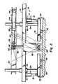
- the apparatus 10 is apparatus for producing vibratory seismic signals. As shown, the apparatus 10 is mounted on frame rails 12 of a vehicle. It is desirable that the apparatus 10 be located on a vehicle because of the large number of locations wherein it is desirable to produce vibratory signals during the course of geophysical or seismic exploration of an area.
- a plurality of lift cylinders 14 project downwardly from the rails 12.
- the cylinders 14 are preferably of the double-acting hydraulic type, and each includes a piston rod 16 that projects therefrom into connection with a lower lift frame 18.
- the arrangement is such that the lift frame 18 can be raised and lowered as desired by actuation of the lift cylinders 14.
- a plurality of guide members 24 connected to the lower frame 18 and extending through sleeves 25 mounted on the vehicle frame 12.
- the sleeves 25 are rigidly mounted to aid in preventing lateral movement of the lift frame 18 relative to the vehicle frame 12 and thus protect the lift cylinders 14. This protection is particularly desirable when using the apparatus on slopes, etc.
- the lift frame 18 is generally rectangular in configuration and is connected to a ground engaging base plate 30 by a plurality of spaced shock absorbing members 32.
- the members 32 are constructed from a resilient material capable of supporting the weight of the base plate 30 so that the base plate 30 will be raised and lowered with the lift frame 18.
- a plurality of tension members 34 are illustrated as being spaced around and extending between the lift frame 18 and the base plate 30.
- the tension members 34 are not required but are desirable so that the weight of the base plate 30 can be carried thereby in the event of a failure in tension of one or more of the shock absorbing members 32 and to aid in preventing such failures.
- a vibrator 36 has its lower end mounted for movement relative to the base plate 30 by means such as a double yoke or U-joint 38.
- the U-joint 38 is provided so that the vibrator 36 can be moved to a variety of positions throughout a range of inclinations and azimuths.
- the upper end of the vibrator 36 is provided with a vibration absorbing coupling 40 for connecting the upper end of the vibrator 36 with a piston 42 of a double-acting hydraulic cylinder 44 and a piston 46 of a double-acting hydraulic cylinder 48.
- the vibration absorbing coupling 40 may be of any suitable type that will isolate the cylinders 44 and 48 from the vibrations created during operation of the vibrator 36.
- the pistons 42 and 46 are each connected with the coupling 40 through yokes or U-joints 50 and 52 to provide freedom of movement between the pistons 42 and 46 and the vibrator 36 during the positioning of the vibrator 36.
- the cylinders 44 and 48 are connected by universal joints 54 and 56 with an upper lift frame 57.
- the upper lift frame 57 is connected to the upper ends of the guide members 24 above the frame 12.
- a sensor 58 is mounted on the cylinder 44 and a sensor 60 is mounted on the cylinder 48.
- the location and arrangement of the sensors 58 and 60 are for illustration only since the exact location will depend upon the type of sensors utilized. However, the sensors 58 and 60 are of a type that will sense the positions of the pistons 42 and 46 relative to the cylinders 44 and 48 and transmit a signal relative to such positions through the conductors 62 and 64.
- the cylinder 44 is provided with conduits 66 and 68.
- the cylinder 48 is provided with conduits 70 and 72.
- the inclination of the vibrator 36 is preferably controllable through an angle of about 25 degrees either side of the vertical, that is, relative to a line perpendicular to the upper surface of the base plate 30. Such angular movement is shown in Figure 2.
- Figure 1 the circle shown as a dash-dot line indicates that azimuths through 360° can be attained by the vibrator 36.
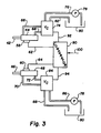
- FIG. 3 illustrates schematically, control means that can be utilized for the purpose of positioning the vibrator 36.
- the conduits 66 and 68 are connected to a control valve 74 which is connected by a conduit 76 with a pump 78.
- the pump 78 is in turn arranged to withdraw hydraulic fluid from a reservoir 80.
- a return conduit 82 also extends from the control valve 74 into the reservoir 80.
- the hydraulic cylinder 48 is connected by the conduits 70 and 72 with a control valve 84 which is connected by a conduit 86 with the hydraulic pump 78.
- Return conduit 88 extends from the control valve 84 to the reservoir 80.
- the control valves 74 and 84 are of a well-known type and are arranged, upon receiving an appropriate signal, to shift to a position wherein one of the conduits connected to the cylinders 44 and 48 will become a supply conduit and the other will become a return conduit, so that the pistons are caused to either move into or extend from their respective cylinders.
- a signal generator 90 such as a comparator or similar electronic device, is provided.
- the comparator 90 is connected by a conductor 92 with the control valve 74 and by a conductor 94 with the control valve 84. It will also be noted that the conductors 62 and 64 extending from the sensors 58 and 60 are connected to the comparator 90.
- the vehicle (not shown) will be positioned so that the axial centerline of the vibrator 36 is positioned over the precise point where it is desired to impart the vibratory seismic signals into the earth.
- Appropriate controls (not shown) are actuated to extend the pistons 16 from the lift cylinders 14 until the base plate 30 engages the ground. When this occurs, further movement of the pistons 16 is arrested but the cylinders 14 lift the frame 12 upwardly until all or a portion of the weight of the vehicle is resting on the base plate 30.
- the vibrator 36 is then positioned in accordance with the desired angle of imposition of the vibratory signal through the base plate 30.
- a signal 100 (See Fig. 3) is fed into the comparator 90 either manually or electronically.
- the comparator 90 transmits a signal through the conductors 92 and 94 to the control valves 74 and 84.
- the control valves are then positioned in accordance with the signal received.
- hydraulic fluid is introduced into the cylinders 44 and 48 through the appropriate conduits. The fluid moves the pistons 42 and 46 to position the vibrator 36 at the desired angle of inclination relative to the base plate 30 and at the desired azimuth.
- Vibrations induced by the vibrator 36 are of a very large force and, consequently, it is highly desirable to isolate the vibrator 36 from all the apparatus with the exception of the base plate 30. Accordingly, the shock isolation means 32 located between the base plate 30 and the lift frame 18 isolate the lifting means, which includes the lift frame and the cylinders 14, and, consequently, the vehicle frame 12 from the vibrations of the base plate 30. At the upper end of the vibrator 36 there is provided the vibration isolating coupling 40 which prevents the transmission of the vibrations through the cylinders 44 and 48 into the vehicle frame 12.
- cylinders 44 and 48 are shown in a preferred relationship of about 90° apart when the axial centerline of the vibrator 36 is perpendicular to the upper surface of the base plate 30, it will be understood that they may be located at other angles relative to each other. Such other arrangements will require appropriate changes to the control program.
Landscapes
- Engineering & Computer Science (AREA)
- Remote Sensing (AREA)
- Physics & Mathematics (AREA)
- Life Sciences & Earth Sciences (AREA)
- Acoustics & Sound (AREA)
- Environmental & Geological Engineering (AREA)
- Geology (AREA)
- General Life Sciences & Earth Sciences (AREA)
- General Physics & Mathematics (AREA)
- Geophysics (AREA)
- Geophysics And Detection Of Objects (AREA)
Claims (7)
- Dispositif vibrateur (10) servant à appliquer des signaux vibratoires sismiques au sol le long d'un trajet vectoriel sélectionné, ledit dispositif étant agencé pour être monté sur un châssis (12) d'un véhicule et comportant une plaque de base (30) apte à s'appliquer au sol, des moyens de levage (14,16,18,57) destinés à être raccordés audit châssis et raccordés à la plaque de base de sorte que ladite plaque de base peut être déplacée depuis une position de transport, dans laquelle elle n'est pas en contact avec le sol, jusqu'à une position de fonctionnement, dans laquelle elle est en contact avec le sol, des moyens vibratoires servant à produire lesdits signaux vibratoires possédant une première extrémité, une seconde extrémité et un axe central, ladite première extrémité étant montée de manière à être déplaçable sur ladite plaque de base, et des moyens de commande (44,48,74,78,80) pour positionner lesdits moyens vibratoires suivant des inclinaisons désirées et des azimuts désirés, lesdits moyens de commande comprenant des premier et second moyens à longueur variable (44,48) et des moyens pour modifier de façon sélective et de façon indépendante la longueur de chacun des moyens à longueur variable pour positionner lesdits moyens vibratoires avec une inclinaison et un azimut désirés, caractérisé en ce que lesdits moyens à longueur variable sont disposés sensiblement perpendiculairement à l'axe central desdits moyens vibratoires lorsque ladite ligne centrale est sensiblement perpendiculaire à ladite plaque de base et lesdits moyens de commande raccordent ladite seconde extrémité desdits moyens vibratoires auxdits moyens de levage et comprennent en outre des moyens comparateurs (90) raccordés de façon opérationnelle auxdits moyens à longueur variable, comportant des moyens générateurs de signaux servant à envoyer un signal amenant lesdits moyens à longueur variable à modifier leur longueur pour positionner lesdits moyens vibratoires avec une inclinaison et un azimut sélectionnés, par comparaison de la longueur desdits moyens à longueur variable avec la longueur requise pour ces moyens lorsque lesdits moyens vibratoires possèdent ladite inclinaison et ledit azimut sélectionnés, et produisant des signaux en réponse à la différence entre ces longueurs pour amener lesdits moyens à longueur variable à déplacer lesdits moyens vibratoires pour régler ladite inclinaison et ledit azimut sélectionnés de ces moyens.
- Dispositif selon la revendication 1, caractérisé en ce que lesdits moyens à longueur variable comprennent un premier vérin à commande hydraulique à double effet (44) et un second vérin à commande hydraulique à double effet (48), disposé d'une manière générale dans le même plan horizontal que ledit premier vérin et perpendiculairement à ce dernier lorsque lesdits moyens vibratoires sont dans une position dans laquelle leur axe central est sensiblement perpendiculaire à ladite plaque de base.
- Dispositif selon la revendication 1 ou 2, caractérisé en ce que des moyens (32) d'atténuation des vibrations sont intercalés entre lesdits moyens vibratoires et lesdits moyens de commande.
- Dispositif selon la revendication 2 ou 3, caractérisé en ce que lesdits moyens (40) d'atténuation des vibrations sont intercalés entre lesdits premier et second vérins hydrauliques et lesdits moyens vibratoires.
- Dispositif selon l'une quelconque des revendications précédentes, caractérisé en ce que lesdits moyens de levage comprennent un cadre de levage (18) qui d'une manière générale est parallèle à une plaque de base tout en en étant distant, une pluralité d'éléments plastiques amortisseurs de chocs (32), qui sont espacés et raccordent ledit cadre de levage et ladite plaque de base, et des moyens formant vérins (14,16) servant à raccorder le châssis du véhicule et le cadre de levage pour soulever et abaisser ledit cadre de levage et ladite plaque de base.
- Dispositif selon la revendication 5, caractérisé en ce que lesdits moyens de levage comprennent également une pluralité d'éléments de tension espacés (34) raccordant ledit cadre de levage et ladite plaque de base.
- Dispositif selon la revendication 6, caractérisé en ce que lesdits moyens de levage comprennent également des éléments de guidage relativement rigide (24) qui s'étendent entre le châssis du véhicule et ledit cadre de levage pour s'opposer à un déplacement latéral entre le châssis du véhicule et ledit cadre de levage.
Applications Claiming Priority (2)
| Application Number | Priority Date | Filing Date | Title |
|---|---|---|---|
| US07/269,403 US4848512A (en) | 1988-11-10 | 1988-11-10 | Vibratory seismic source |
| US269403 | 1988-11-10 |
Publications (3)
| Publication Number | Publication Date |
|---|---|
| EP0368440A2 EP0368440A2 (fr) | 1990-05-16 |
| EP0368440A3 EP0368440A3 (en) | 1990-11-28 |
| EP0368440B1 true EP0368440B1 (fr) | 1992-11-25 |
Family
ID=23027094
Family Applications (1)
| Application Number | Title | Priority Date | Filing Date |
|---|---|---|---|
| EP89306512A Expired EP0368440B1 (fr) | 1988-11-10 | 1989-06-27 | Source sismique vibratoire |
Country Status (5)
| Country | Link |
|---|---|
| US (1) | US4848512A (fr) |
| EP (1) | EP0368440B1 (fr) |
| AU (1) | AU607341B2 (fr) |
| CA (1) | CA1308187C (fr) |
| DE (1) | DE68903626T2 (fr) |
Families Citing this family (10)
| Publication number | Priority date | Publication date | Assignee | Title |
|---|---|---|---|---|
| US4853907A (en) * | 1989-02-17 | 1989-08-01 | Atlantic Richfield Company | Inclinable vibratory seismic source |
| US5187331A (en) * | 1991-03-28 | 1993-02-16 | Agency Of Industrial Science And Technology | SH wave generator |
| US5252785A (en) * | 1992-01-07 | 1993-10-12 | Industrial Vehicles International | Broad band seismic vibrator |
| US5666328A (en) * | 1996-10-18 | 1997-09-09 | I/O Exploration Products (U.S.A.), Inc. | Three axis seismic vibrator |
| US6065562A (en) * | 1998-07-27 | 2000-05-23 | Industrial Vehicles International, Inc. | System for imparting compressional and shear waves into the earth |
| US20050100417A1 (en) * | 2003-11-07 | 2005-05-12 | Geopartner Sp. Z O.O | Method of deep soil compacting from a surface |
| US7918307B2 (en) * | 2004-02-03 | 2011-04-05 | United Service Alliance, Inc. | Accelerated weight drop for use as a seismic energy source and a method of operation thereof |
| US8261875B2 (en) * | 2010-02-18 | 2012-09-11 | Conocophillips Company | Seismic transducers and baseplates having external dampeners and methods of use |
| US8689930B2 (en) * | 2012-03-29 | 2014-04-08 | Westerngeco L.L.C. | Seismic vibrator having airwave suppression |
| US9651692B2 (en) * | 2015-05-08 | 2017-05-16 | Sercel | Vibrator truck with a lift system comprising at least one flexible strap |
Family Cites Families (3)
| Publication number | Priority date | Publication date | Assignee | Title |
|---|---|---|---|---|
| US4660674A (en) * | 1984-11-30 | 1987-04-28 | Atlantic Richfield Company | Mounting and control means for full waveform seismic source |
| GB2182440B (en) * | 1985-10-29 | 1989-10-11 | Atlantic Richfield Co | Full wave field vibratory seismic source |
| US4662473A (en) * | 1986-01-13 | 1987-05-05 | Atlantic Richfield Company | Vibratory seismic source for generating combined compressional and shear waves |
-
1988
- 1988-11-10 US US07/269,403 patent/US4848512A/en not_active Expired - Fee Related
-
1989
- 1989-06-15 CA CA000602961A patent/CA1308187C/fr not_active Expired - Lifetime
- 1989-06-27 DE DE8989306512T patent/DE68903626T2/de not_active Expired - Fee Related
- 1989-06-27 EP EP89306512A patent/EP0368440B1/fr not_active Expired
- 1989-06-30 AU AU37271/89A patent/AU607341B2/en not_active Ceased
Also Published As
| Publication number | Publication date |
|---|---|
| CA1308187C (fr) | 1992-09-29 |
| DE68903626D1 (de) | 1993-01-07 |
| EP0368440A3 (en) | 1990-11-28 |
| DE68903626T2 (de) | 1993-04-15 |
| EP0368440A2 (fr) | 1990-05-16 |
| US4848512A (en) | 1989-07-18 |
| AU3727189A (en) | 1990-05-17 |
| AU607341B2 (en) | 1991-02-28 |
Similar Documents
| Publication | Publication Date | Title |
|---|---|---|
| US4805725A (en) | Nondestructive downhole seismic vibrator source and processes of utilizing the vibrator to obtain information about geologic formations | |
| US4321981A (en) | Combination shear wave and compressional wave seismic energy vibrator | |
| US4853907A (en) | Inclinable vibratory seismic source | |
| US6179084B1 (en) | Underground acoustic wave transmitter, receiver, transmitting/receiving method, and underground exploration using this | |
| US5080189A (en) | Electro-hydraulic dipole vibrator | |
| EP0368440B1 (fr) | Source sismique vibratoire | |
| US5042611A (en) | Method and apparatus for cross-well seismic surveying | |
| US4719607A (en) | Full wave field vibratory seismic source | |
| EP0230372B1 (fr) | Source sismique vibratoire pour engendrer en combinaison des ondes longitudinales et transversales | |
| WO2015023376A1 (fr) | Acquisition sismique à basse fréquence utilisant un vibrateur de masse excentrique contrarotatif | |
| US4660675A (en) | Vibratory seismic source for generating combined compressional and shear waves | |
| US5128900A (en) | Multi-component seismic vibratory source for use in marine environments | |
| US4248324A (en) | Seismic vibrator and method for improving the output of a seismic vibrator | |
| US20090086574A1 (en) | Superheterodyne seismic vibrator and method | |
| US4959818A (en) | Apparatus for generating elliptically polarized shear waves | |
| US5187331A (en) | SH wave generator | |
| EP0256627B1 (fr) | Dispositif de génération des ondes transversales dans un milieu terrestre | |
| CA1192986A (fr) | Commande-regulation de vibrateur sismique | |
| CA1125905A (fr) | Methode de prospection sismique par ondes de cisaillement | |
| JPS6350782A (ja) | ア−ス媒体中の楕円偏波シ−ア波誘起のための方法および装置 | |
| US20120037446A1 (en) | Uniform displacement sweep |
Legal Events
| Date | Code | Title | Description |
|---|---|---|---|
| PUAI | Public reference made under article 153(3) epc to a published international application that has entered the european phase |
Free format text: ORIGINAL CODE: 0009012 |
|
| AK | Designated contracting states |
Kind code of ref document: A2 Designated state(s): DE FR GB |
|
| PUAL | Search report despatched |
Free format text: ORIGINAL CODE: 0009013 |
|
| AK | Designated contracting states |
Kind code of ref document: A3 Designated state(s): DE FR GB |
|
| 17P | Request for examination filed |
Effective date: 19901214 |
|
| 17Q | First examination report despatched |
Effective date: 19910821 |
|
| GRAA | (expected) grant |
Free format text: ORIGINAL CODE: 0009210 |
|
| AK | Designated contracting states |
Kind code of ref document: B1 Designated state(s): DE FR GB |
|
| REF | Corresponds to: |
Ref document number: 68903626 Country of ref document: DE Date of ref document: 19930107 |
|
| ET | Fr: translation filed | ||
| PGFP | Annual fee paid to national office [announced via postgrant information from national office to epo] |
Ref country code: GB Payment date: 19930604 Year of fee payment: 5 |
|
| PGFP | Annual fee paid to national office [announced via postgrant information from national office to epo] |
Ref country code: FR Payment date: 19930625 Year of fee payment: 5 |
|
| PGFP | Annual fee paid to national office [announced via postgrant information from national office to epo] |
Ref country code: DE Payment date: 19930730 Year of fee payment: 5 |
|
| PLBE | No opposition filed within time limit |
Free format text: ORIGINAL CODE: 0009261 |
|
| STAA | Information on the status of an ep patent application or granted ep patent |
Free format text: STATUS: NO OPPOSITION FILED WITHIN TIME LIMIT |
|
| 26N | No opposition filed | ||
| PG25 | Lapsed in a contracting state [announced via postgrant information from national office to epo] |
Ref country code: GB Effective date: 19940627 |
|
| GBPC | Gb: european patent ceased through non-payment of renewal fee |
Effective date: 19940627 |
|
| PG25 | Lapsed in a contracting state [announced via postgrant information from national office to epo] |
Ref country code: FR Effective date: 19950228 |
|
| PG25 | Lapsed in a contracting state [announced via postgrant information from national office to epo] |
Ref country code: DE Effective date: 19950301 |
|
| REG | Reference to a national code |
Ref country code: FR Ref legal event code: ST |