EP0368502B1 - Présentoir de marchandise rotatif et articulé - Google Patents
Présentoir de marchandise rotatif et articulé Download PDFInfo
- Publication number
- EP0368502B1 EP0368502B1 EP89310879A EP89310879A EP0368502B1 EP 0368502 B1 EP0368502 B1 EP 0368502B1 EP 89310879 A EP89310879 A EP 89310879A EP 89310879 A EP89310879 A EP 89310879A EP 0368502 B1 EP0368502 B1 EP 0368502B1
- Authority
- EP
- European Patent Office
- Prior art keywords
- column
- display unit
- generally
- central support
- tray
- Prior art date
- Legal status (The legal status is an assumption and is not a legal conclusion. Google has not performed a legal analysis and makes no representation as to the accuracy of the status listed.)
- Expired - Lifetime
Links
- 230000000295 complement effect Effects 0.000 claims description 3
- 230000005484 gravity Effects 0.000 claims description 2
- 230000008878 coupling Effects 0.000 description 5
- 238000010168 coupling process Methods 0.000 description 5
- 238000005859 coupling reaction Methods 0.000 description 5
- 239000000463 material Substances 0.000 description 2
- 229920003023 plastic Polymers 0.000 description 2
- 229920002972 Acrylic fiber Polymers 0.000 description 1
- 239000004677 Nylon Substances 0.000 description 1
- 150000001875 compounds Chemical class 0.000 description 1
- -1 for instance Substances 0.000 description 1
- 229920001778 nylon Polymers 0.000 description 1
- 230000002093 peripheral effect Effects 0.000 description 1
- 239000004033 plastic Substances 0.000 description 1
- 230000001737 promoting effect Effects 0.000 description 1
- 230000000717 retained effect Effects 0.000 description 1
- 239000012780 transparent material Substances 0.000 description 1
Images

Classifications
-
- A—HUMAN NECESSITIES
- A47—FURNITURE; DOMESTIC ARTICLES OR APPLIANCES; COFFEE MILLS; SPICE MILLS; SUCTION CLEANERS IN GENERAL
- A47F—SPECIAL FURNITURE, FITTINGS, OR ACCESSORIES FOR SHOPS, STOREHOUSES, BARS, RESTAURANTS OR THE LIKE; PAYING COUNTERS
- A47F5/00—Show stands, hangers, or shelves characterised by their constructional features
- A47F5/04—Stands with a central pillar, e.g. tree type
- A47F5/05—Stands with a central pillar, e.g. tree type with separate containers rotatable around the pillar
Definitions
- the present invention relates to a rotatable merchandise display unit for displaying various types of merchandise, such as for instance greeting cards and the like, and more particularly relates to a rotatable display unit having a plurality of generally vertical rows of radially extending merchandise receiving pockets or structures, disposed in generally lateral relationship with respect on one another around an articulated column structure rotatable with respect to a central support wherein the column structure and mounted row of merchandise receiving pockets are adapted to undulate or pivot with respect on one another during rotation of the column and pockets about the central support.
- Spinner type display units generally consist of a rotatable column or columns, on which are mounted merchandise display shelves or trays, with the shelves or trays having upwardly facing pockets for receiving and displaying merchandise therein, such as for instance greeting cards, or other types of merchandise. These shelves or trays do not usually move relative to one another during rotation of the display unit about its vertical axis.
- DE-A-23 58 832 discloses a rotatable display stand made up of a number of stacked tiers according to the preamble of claim 1.
- Each tier comprises a plurality of cuboid boxes, each box being attached to adjacent boxes at diagonally opposite corners. Some, but not all, of the boxes in each tier are pivotally mounted on a support, the resulting limited rotational freedom of movement being utilised to enable differing numbers of boxes to be accommodated in each tier.
- the tiers are clamped together to prevent relative movement of the boxes within any tier, and therefore to preserve the basic shape of the stand.
- the present invention provides a merchandise display unit comprising: a generally vertical central support; an elongated column rotatably mounted on said support, said column being of generally polygonal configuration in plan and including sides hinged to one another; and merchandise receiving trays extending outwardly from said column sides; characterised in that the column sides are free to rotate with respect to each other about said hinges, and in that each column side is supported by said central support in a manner allowing pivotal movement of the side with respect to the central support, whereby, when any one column side is rotated in operation about its point of engagement by said central support, the column sides adjacent thereto each maintain a parallel relationship with a respective predetermined diameter of said central support.
- Embodiments of apparatus according to the invention not only enable better viewing of the merchandise disposed in the pockets of trays, but also present unique attention-getting motion during rotation of the display unit.
- the inner sides of the column are provided with cam means to coact with the central support;
- the rows of merchandise receiving pockets or trays consist of members disposed in generally stacked relationship and which are removably coupled to the articulated column by coacting track and wing means;
- the merchandise receiving trays are formed of translucent or transparent plastic so that the merchandise in each tray pocket is visible through the retaining sidewalls thereof;
- the rotatable column of the unit is formed of vertically elongated webs hinged to one another to form column structure having in plan a generally hexagonal configuration, in one reposed condition of the column.
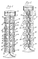
- a "spinner type" portable, merchandise display unit 10 embodying the invention, and comprising in the embodiment illustrated, a base 12 having a generally vertical, central support or post 14 extending upwardly therefrom, with a header structure 16 mounted on the upper end of the central support 14 and adapted to have advertising indicia shown thereon, promoting the merchandise M displayed by unit 10.
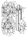
- an elongated column 18 (FIGURE 3) which comprises a polygonal shaped structure in plan (FIGURES 4 and 5) including side members 19 which are hinged or coupled to one another at their adjacent edges, so that the side members 19 can pivot or hingedly move relative to one another during rotation of the column structure 18 about the central support 14.
- Merchandise receiving trays 22 are mounted on a respective side member 19 of the column, and in the embodiment illustrated are removably mounted, so as to project generally radially outwardly from the respective side member 19 and thus move or undulate relative to one another during the hinged movement of the side members of the column, relative to one another upon rotation of the column about support 14.
- Each of the side members 19 in the embodiment illustrated has inwardly projecting flanges representing track structure 24 on its outer face, adjacent its side edges, and each tray 22 preferably has wing structure 26 (FIGURES 4 and 5) at its inner end, which is received in the track structure 24 of the respective side member, so as to slidably mount the respective merchandise receiving tray 22 on its respective side member, and as aforementioned in radially projecting relation to the respective side member.
- wing structure 26 FIGURES 4 and 5
- Each of the merchandise receiving trays 22 comprises, in the embodiment illustrated, a receptacle 28 (FIG. 3) having a generally central web 30 projecting upwardly therefrom and dividing the receptacle into lateral merchandise receiving sections 28a, 28b, which are adapted to receive therein merchandise, such as for instance, greeting cards.
- the bottom wall of receptacle 28 preferably slopes downwardly and outwardly as at 31 from the central web 30, as best seen in FIGURE 3, and thus by gravity, urges the merchandise M in the trays outwardly toward the exterior respective side wall of the receptacle 28.
- Such sloping bottom wall sections 31 provides a recess extending lengthwise of the receptacle, which is adapted to receive therein the central web 30 on the underlying receptacle, and thus position and stack the merchandise receiving trays relative to one another in vertically oriented, laterally spaced rows on the column, and providing the "spinner" structure illustrated in FIGURES 1 and 2.
- Merchandise receiving trays 22 are preferably formed of translucent or transparent material, such as for instance acrylic plastic, so that the merchandise can be generally viewed through the tray structure.
- Each of the column side members 19 in the embodiment illustrated comprises a generally vertically extending elongated web portion 32 and an arm portion 32a extending inwardly from the web portion 32 in the direction of the central support 14, with a circular (in the embodiment illustrated) cam 32b being provided on the distal end of arm 32a, adapted for engagement with a collar 34 (FIGURES 6 and 15) which is mounted on and preferably secured to the central support 14.
- Cammed arms 32a engage the collar for supporting or mounting the column 18 on the central support 14, with the column being rotatably movable relative to the collar 34, during rotation of the column 18 on central support 14.
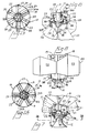
- the lower end of the central support 14 generally adjacent base 12 may also include a collar structure 36 (FIGURES 7 and 8) preferably secured to support 14, and which collar provides a generally horizontal surface 36a, which provide a support for glides or cams 37 attached to the underside of the respective arm 32a of each side of the column 18, with such glides 37 engaging surface 36a and aiding in supporting the hinged column 18 and associated merchandise trays 22 on the central support 14, in movable relation thereto.
- Glides 37 may be and preferably are formed of some low resistance material, such as for instance, nylon plastic, for ease of movement with respect to surface 36a, upon rotation of the column and associated merchandise receiving trays about the central support.
- FIGURES 9 through 14 there is shown in detail the hinge bracket members 38, used to hinge one side member 19 to the adjacent member 19, to form the hinged column structure 18.
- Hinge bracket member 38 comprises, in the embodiment illustrated, a generally horizontally oriented base portion 38a with a generally circular in transverse cross section, male projection 38b extending from the base portion 38a in generally perpendicular relationship with respect thereto, and with a plurality of generally deformable or yieldable finger portions 38c likewise projecting from the base portion 38a, in generally parallel relationship to the axis of the cylindrical-like male projection 38b.
- Bracket 38 is preferably formed of moldable or castable material, and as best seen in FIGURE 14 is assemblable with the respective adjacent side members 19 of the column 18 and on the upper and lower ends thereof for hinging the adjacent side members together.
- each side member 19 has a circular opening or passageway 40 formed therein generally adjacent a vertical edge thereof, adapted to receive in relatively rotatable relation the aforementioned male projection 38b on the respective hinge bracket 38, and adjacent the other vertical edge thereof, is provided with a non-circular opening 42, which is adapted to receive therein in generally wedging relationship the deformable fingers 38c of an associated hinge bracket, for securing the bracket 38 in the associated opening 42, and thus hinging the pair of adjacent side members 19 of the column together.
- the opening 42 is non-circular in plan, generally D configuration in plan in the embodiment illustrated (FIGURE 9) including a generally flat defining surface 42a and a generally curved defining surface 42b, and that the finger structure 38c likewise represents a generally D-like configuration, in plan, substantially complementary to opening 42 for wedging relation therein.
- Transverse structure 38c′ of finger 38c is adapted for generally flat surface-to-surface engagement with complementary surface 42a of opening 42 while the other radially extended finger sections of finger structure 38c project outwardly from the transverse portion and in the general direction of the cylindrical pivot portion 38b of the hinge bracket 38, thus securing the hinge bracket to its respective mounting side member 19 and yet providing for pivotal movement of the adjacent side member relative to the respective side member (via the receipt of the cylindrical male portion 38b within the opening 40 in such adjacent side member 19 and as shown in FIGURE 14.
- the bracket 38 may be provided with a hub portion 46 on its underside, from which the finger structure 38c projects, and which causes commencement of the projection of the fingers at a lower elevation (as viewed in FIGURE 11) as compared to the commencement of projection of the cylindrical male portion 38b, thus insuring that the pivotal or hinged side 19 is not engaged tightly between the base portions 38a of the respective pair of upper and lower brackets pivoting the adjacent side member 19 to the respective side member, when the cylindrical male portions 38b of the upper and lower hinge brackets are received in the respective receiving opening 40 therein, thus maintaining a non-binding hinged relationship between the pair of adjacent hinged side members 19.
- tray A rotating counterclockwise around the center of its cam 32b as a pivot point. During this movement, the cam remains essentially on the same radius r of center support 14.
- tray B moves along an arcuate path generating a compound motion, one component of which moves the tray inwardly toward support 14 while another component moves the tray counterclockwise around a vertical axis through the center of support 14.
- the tray is retained in an essentially rectilinear relationship with diameter d through the center of support 14.
- the inner and outer ends of the tray remain parallel to diameter d and its sides remain perpendicular to diameter d (compare FIGURES 4 and 5).
- tray B its associated cam 32b slides downwardly (with reference to FIGURES 4 and 5) along the peripheral surface of collar 34, and in the direction of cam 32b associated with tray C.
- Trays C and E undergo the identical motion described above for tray A; and trays D and F undergo the identical motion described above for tray B.
- FIGURE 5 shows the configuration of the trays at the far reach of the above-described motion. Contact between pairs of cam 32b brings the motion program to an end.
- tray A Once the stage depicted in FIGURE 5 is reached, the application of additional force to the right hand side of tray A will cause all six trays to move in tandem, in a circular path around a vertical axis through the center of support 14.
- Tray A will rotate clockwise around its cam 32b as a pivot point.
- Tray F will move along an arcuate path while essentially maintaining its rectilinearity with respect to a fixed diameter through the center of support 14.
- cam 32b associated with trays A and F instead of cam 32b associated with trays A and F being in contact at the far reach of the motion (see FIGURE 5) tray A's cam 32b will be in contact with cam 32b associated with tray B, and tray F's cam 32b will be in contact with cam 32b associated with tray E.
- the FIGURE 5 configuration can be returned to the FIGURE 4 configuration by either (a) applying a clockwise force to the side of tray C closer to tray D, or the side of tray A closer to tray B, or the side of E closer to tray D; or (b) applying a counterclockwise force to the side of tray D closer to tray C, or the side of tray B closer to tray A, or the side of tray F closer to tray E.
- Operation of the merchandise display unit may be as follows: When a purchaser wants to view further of the merchandise disposed in the trays 22, he will turn the unit by pushing or applying rotative force to the outwardly projecting trays, causing rotation of the column 18 and attached merchandise trays about the central support 14. If the hinged column and associated tray structure are in the position shown in FIGURE 4, wherein the column 18 (in plan) defines a generally hexagonal configuration, application of rotary force to the trays and associated column by the customer will cause turning of the column and assorted trays on the central support 14, will cause the side members 19 forming the column 18 to pivot or move with respect to one another and to a position illustrated in FIGURE 5, wherein the column 18 defines, in plan, a generally triangular shape configuration.
- the side members 19 will pivot or move relative to one another about the male projecting portions 38b, and the cam portions 32b disposed on the inwardly projecting arms 32a of each side member 19 forming the column structure 18, will move relative to the collar 34 into the position illustrated, for instance, in FIGURE 5 wherein the cam portions 32b have moved into generally abutting engagement with respect to one another.
- the hinged column side member structure 19 and associated trays will move again relative to one another, to, for instance, back to the position shown, for instance, in FIGURE 4 or some other intermediate position. It will be seen therefore, that the column side members and associated vertical rows of merchandise display trays 22 undulate or pivot with respect to one another during application of rotative force to the column and tray structure by the customer, the latter causing rotary movement of the column and associated merchandise display trays about the central support 14.
- This novel undulating movement of the hinged sides of the column and associated merchandise display trays, relative to one another, provides a unique appearance to the display unit as it is rotated about the central support, as well as providing for excellent observation of the merchandise disposed in the merchandise display trays.
- the invention provides a novel rotatable, merchandise display unit comprising a generally vertical central support, supporting a vertically elongated column-like structure thereon and in rotatable relation therewith, with the column being formed of hinged side members and having a plurality of generally vertical rows or merchandise receiving trays disposed along the plural sides of the column in literally spaced relation with respect to one another, with each of the rows of trays providing pockets or receptacles for receiving therein merchandise for display, and with the display unit being so constructed and arranged that the merchandise receiving tray structure and side members forming the associated supporting column structure undulate or pivot with respect to one another during rotation of the column structure and associated tray structure about the central support.
- the invention also provides a merchandise display unit of the aforementioned type wherein the rows of merchandise receiving tray members are comprised of tray members disposed in generally stacked relationship, which are removably coupled to the hinged column.
- the invention also provides a rotatable merchandise display unit of the aforementioned type wherein the tray structure is removably coupled to the hinged column structure by means of coacting wing and track structure.
Landscapes
- Display Racks (AREA)
Claims (14)
- Unité de présentation de marchandises comprenant : un support central vertical (14), une colonne de forme allongée (18) montée de façon à tourner autour dudit support (14) ladite colonne (18) étant généralement, vue en plan, de configuration polygonale et comprenant des éléments latéraux (19) articulés les uns aux autres; et des plateaux pour recevoir des marchandises (22) saillant vers l'extérieur à partir des éléments (19) de la colonne; caractérisée en ce que lesdits éléments (19) sont libres de tourner l'un par rapport à l'autre autour de moyens d'articulation (38), et en ce que chaque élément (19) de la colonne est disposé sur le support central (14) d'une manière permettant un mouvement pivotant de cet élément latéral (19) par rapport au support central (14), de façon que, lorsqu'un quelconque des éléments latéraux (19) de la colonne se met à tourner autour de son point d'engagement (32b) avec le support central (14), ces éléments latéraux (19) adjacents à la colonne conservent chacun un mouvement parallèle à une ligne prédéterminée (d) passant diamétralement au travers dudit support central (14).
- Unité de présentation (10) selon la revendication 1, dans laquelle chacun des éléments latéraux (19) de la colonne comprend un panneau vertical de forme allongée (32) constituant un élément de la colonne (18), chacun de ces panneaux (32) étant muni d'un bras (32a) saillant vers l'intérieur depuis la surface du côté interne et ayant une partie en forme de came (32b) sur l'extrémité dudit bras (32a), ces parties en forme de came (32b) étant adaptées pour s'engager dans le support central (14) et positionner ainsi la colonne (18) sur le support central (14).
- Unité de présentation (10) selon la revendication 2, dans laquelle le support central (14) comprend un collier (34) manchonné sur lui à l'endroit ou chaque came (32b) engage ce collier, pour supporter les éléments latéraux de la colonne (18) et les positionner sur ledit support central (14).
- Unité de présentation (10) selon l'une quelconque des revendication précédentes, dans laquelle la colonne (18) comprend six éléments (19) articulés l'un à l'autre.
- Unité de présentation (10) selon l'une quelconque des revendications précédentes, dans laquelle la colonne (18) est construite et disposée de telle sorte qu'elle change d'une configuration en plan hexagonale en une configuration en plan de préférence triangulaire et vice et versa pendant le mouvement pivotant des éléments latéraux (19) et des plateaux (22) par rapport au support (14).
- Unité de présentation (10) selon l'une quelconque des revendications précédentes, comprenant des moyens (24, 26) permettant de détacher les plateaux (22) d'au moins quelques-uns de leurs éléments latéraux (19) respectifs.
- Unité de présentation (10) selon la revendication 6, dans laquelle les moyens comprennent des bras (26) sur chaque plateau (22) agissant conjointement avec les glissières (24) situées sur les éléments latéraux respectifs (19) de la colonne (18).
- Unité de présentation (10) selon l'une quelconque des revendications précédentes, dans laquelle chaque plateau (22) comprend une enceinte (28) ayant un panneau central vertical (30) divisant ladite enceinte (28) en sections latérales (28a, 28b), et dont la paroi de fond (31) de chacune de ces sections est montée diagonalement, en pente, dirigée vers le bas et vers l'extérieur de façon que les marchandises disposées dans le plateau respectif (22) soient latéralement poussées par gravité vers le côté extérieur des sections respectives (28a, 28b).
- Unité de présentation (10) selon la revendication 2 ou l'une quelconque des revendications qui en découlent, dans laquelle chaque bras (32a) comprend une came saillant vers le bas (32b) adaptée pour s'engager dans le support radial (36a) sur le support central (14), et pour soutenir le panneau latéral respectif (19) de la colonne (18) sur ledit support central (14), pendant la rotation de ladite colonne (18) et des plateaux (22) par rapport audit support central (14) et audit support radial (36a).
- Unité de présentation (10) selon l'une quelconque des revendications précédentes dans laquelle chaque élément latéral (19) comprend le long d'une de ses extrémités transversales une ouverture non-circulaire (42) s'étendant généralement verticalement sur toute sa longueur, et une ouverture de préférence circulaire (40) s'étendant de préférence verticalement à l'autre extrémité transversale, et une charnière à deux points d'ancrage (38) présentant une partie mâle circulaire à section en forme de croix (38b) adjacente à une des extrémités et adaptée pour être insérée dans l'ouverture circulaire (40) de l'élément latéral adjacent (19), et ladite charnière à deux points d'ancrage (38) comprenant une partie mâle non-circulaire à section en croix (38c) adaptée pour être insérée dans l'ouverture non-circulaire (42) de l'élément latéral respectif (19), ou vice et versa, de façon que le mouvement de pivot de l'élément latéral adjacent (19) avec l'ouverture à section circulaire (40) puisse ainsi avoir lieu par rapport à l'élément latéral (19) et à la charnière montée à deux points d'ancrage (38), fournissant ainsi la relation d'articulation par charnière d'un élément (19) par rapport à l'autre.
- Unité de présentation (10) selon la revendication 10, dans laquelle la charnière à deux points d'ancrage (38) comprend une base orientée de préférence horizontalement (38a), la partie mâle circulaire à section en croix (38b), saillant vers le bas depuis une extrémité adjacente à la base (38a), et une pluralité de doigts généralement déformables (38c) saillant vers le bas depuis le support à deux points d'ancrage (38) adjacent à l'autre extrémité de la base (38a) et comprenant une partie mâle non-circulaire à section en croix (38c) dans laquelle lesdits doigts (38c) sont lors du fonctionnement insérés en force dans l'ouverture non-circulaire (42) ménagée dans l'élément latéral respectif (19) de la colonne (18) pour immobiliser la charnière (38).
- Unité de présentation (10) selon la revendication 11, dans laquelle la base (38a) est dotée d'un moyeu (46) sur la surface inférieure duquel les doigts (38c) solidaires dudit moyeu (46), leur permettent depuis la base (38a) une position inférieure comparée à celle que la partie mâle circulaire à section en croix (38b) peut avoir.
- Unité de présentation (10) selon la revendication 11, dans laquelle l'ouverture non-circulaire (42) ménagée dans l'élément latéral respectif (19) a en plan une configuration généralement en forme de D, dans laquelle les doigts (38c) saillent radialement vers l'extérieur dans la direction générale de la partie mâle circulaire à section en croix (38b) de la charnière (38), lesdits doigts (38c) définissant ainsi en plan une configuration généralement en forme de D complémentaire de la configuration en forme de D de l'ouverture non-circulaire (42) de l'élément latéral respectif (19).
- Unité de présentation (10) selon la revendication 8, dans laquelle un panneau central (30) saille vers le haut au-dessus des sections latérales (28a, 28b) et est reçu dans la base en retrait du plateau (22) s'étendant au-dessus pour orienter les plateaux l'un par rapport à l'autre dans une direction verticale, ladite base en retrait dans le plateau s'étendant au-dessus étant délimitée par les parois de fond en pente (31) des sections latérales (28a, 28b) dudit plateau (22).
Applications Claiming Priority (2)
| Application Number | Priority Date | Filing Date | Title |
|---|---|---|---|
| US269233 | 1988-11-09 | ||
| US07/269,233 US4976359A (en) | 1988-11-09 | 1988-11-09 | Rotatable articulated merchandise display unit |
Publications (3)
| Publication Number | Publication Date |
|---|---|
| EP0368502A2 EP0368502A2 (fr) | 1990-05-16 |
| EP0368502A3 EP0368502A3 (en) | 1990-10-17 |
| EP0368502B1 true EP0368502B1 (fr) | 1993-12-29 |
Family
ID=23026384
Family Applications (1)
| Application Number | Title | Priority Date | Filing Date |
|---|---|---|---|
| EP89310879A Expired - Lifetime EP0368502B1 (fr) | 1988-11-09 | 1989-10-23 | Présentoir de marchandise rotatif et articulé |
Country Status (5)
| Country | Link |
|---|---|
| US (1) | US4976359A (fr) |
| EP (1) | EP0368502B1 (fr) |
| AU (1) | AU614915B2 (fr) |
| CA (1) | CA2000302C (fr) |
| ES (1) | ES2049334T3 (fr) |
Families Citing this family (17)
| Publication number | Priority date | Publication date | Assignee | Title |
|---|---|---|---|---|
| US5083670A (en) * | 1988-04-27 | 1992-01-28 | John J. Zimmer | Revolving storage device for small items |
| US5280839A (en) * | 1991-11-08 | 1994-01-25 | Christina Investments Pty Ltd. | Displaying and stocking |
| US5472100A (en) * | 1993-07-15 | 1995-12-05 | Hamilton Fixture Company | Greeting card display rack |
| DE29506656U1 (de) | 1995-04-19 | 1996-04-25 | Wolf-Dietrich Hannecke Kunststofftechnik, 37154 Northeim | Warenpräsentationssystem in Modulbauweise |
| US5715955A (en) * | 1995-12-14 | 1998-02-10 | Hannecke; Wolf-Dietrich | Merchandise presentation system of modular design |
| DE19701255A1 (de) | 1997-01-16 | 1998-07-23 | Hannecke Wolf D Kunststoff | Vorrichtung zur Präsentation flacher oder biegsamer Gegenstände |
| DE19701257A1 (de) | 1997-01-17 | 1998-07-23 | Hannecke Wolf D Kunststoff | Säulenpräsentationssystem in Modulbauweise zur Schaustellung von Waren oder Prospektmaterial und insbesondere von dünnen Gegenständen |
| US6424322B1 (en) * | 1998-10-05 | 2002-07-23 | Jesse D. Northcutt | Multi-module stereoscopic 3D video viewing/listening station |
| US6006911A (en) * | 1998-10-13 | 1999-12-28 | Levy; Abner | Specimen slide holder with integral closure fastener |
| US6612052B2 (en) | 2001-08-01 | 2003-09-02 | Beth A. Sawchuk | Display device |
| EP1471810A1 (fr) | 2002-02-07 | 2004-11-03 | Rubbermaid Incorporated | Element de rayonnage d'angle a plusieurs tages |
| US6752281B1 (en) * | 2003-03-20 | 2004-06-22 | New Dimensions Research Corporation | Display device |
| USD523681S1 (en) | 2005-11-23 | 2006-06-27 | Shahriar Dardashti | Wire spinner multimedia rack |
| US8534472B2 (en) * | 2009-09-16 | 2013-09-17 | Universal Presentation Concepts | Spinning tower rack |
| US9492020B1 (en) | 2015-07-17 | 2016-11-15 | Chicago Display Company | Display rack |
| US9918567B2 (en) | 2015-09-15 | 2018-03-20 | Tracfone Wireless, Inc. | Display rack system |
| CN112258937B (zh) * | 2020-11-19 | 2022-04-19 | 王明明 | 一种便于收纳汽车教具的旋转展示装置 |
Family Cites Families (8)
| Publication number | Priority date | Publication date | Assignee | Title |
|---|---|---|---|---|
| US1432286A (en) * | 1921-02-23 | 1922-10-17 | Universal Fixture Corp | Display fixture |
| US1569365A (en) * | 1923-08-16 | 1926-01-12 | Universal Fixture Corp | Display fixture |
| US3223247A (en) * | 1964-07-30 | 1965-12-14 | Commercial Wire Products Co | Revolving display rack |
| US3314551A (en) * | 1965-03-11 | 1967-04-18 | Design And Production Inc | Display device |
| US4079841A (en) * | 1976-12-10 | 1978-03-21 | Coats & Clark, Inc. | Modular display unit for books or the like, and module for use therein |
| US4247010A (en) * | 1978-08-07 | 1981-01-27 | Dlm, Inc. | Display stand and method of making same |
| US4339164A (en) * | 1979-05-14 | 1982-07-13 | Potomac Applied Mechanics, Inc. | Article supporting assembly |
| US4586619A (en) * | 1983-05-09 | 1986-05-06 | Thomas A. Schutz Co., Inc. | Eyeglass frame display |
-
1988
- 1988-11-09 US US07/269,233 patent/US4976359A/en not_active Expired - Lifetime
-
1989
- 1989-10-06 CA CA002000302A patent/CA2000302C/fr not_active Expired - Fee Related
- 1989-10-12 AU AU42841/89A patent/AU614915B2/en not_active Ceased
- 1989-10-23 EP EP89310879A patent/EP0368502B1/fr not_active Expired - Lifetime
- 1989-10-23 ES ES89310879T patent/ES2049334T3/es not_active Expired - Lifetime
Also Published As
| Publication number | Publication date |
|---|---|
| EP0368502A3 (en) | 1990-10-17 |
| CA2000302C (fr) | 1995-01-03 |
| ES2049334T3 (es) | 1994-04-16 |
| US4976359A (en) | 1990-12-11 |
| AU614915B2 (en) | 1991-09-12 |
| AU4284189A (en) | 1990-05-17 |
| CA2000302A1 (fr) | 1990-05-09 |
| EP0368502A2 (fr) | 1990-05-16 |
Similar Documents
| Publication | Publication Date | Title |
|---|---|---|
| US4976359A (en) | Rotatable articulated merchandise display unit | |
| US5226548A (en) | I-frame support for a rotatable display tower | |
| US4673090A (en) | Modular expandable merchandise display rack | |
| US8534472B2 (en) | Spinning tower rack | |
| US7654399B2 (en) | Configurable display system and modular display arrangement for consumer electronic devices | |
| EP0211816B1 (fr) | Support à plateaux | |
| US5405193A (en) | Computer video game pak display cabinet | |
| US20010017284A1 (en) | Showcase assembly unit for showcase structure | |
| US4919383A (en) | Rotating display | |
| US4247010A (en) | Display stand and method of making same | |
| US5259517A (en) | Vertically spaced multiple rail display racks | |
| US20120031865A1 (en) | Adjustable divider system | |
| US5335795A (en) | Storage rack for cassettes and compact discs | |
| US4534473A (en) | Display stand | |
| US6942109B2 (en) | Rotary display apparatus for displaying periodicals in a circular array | |
| WO1999005942A1 (fr) | Presentoir a etageres | |
| US5259515A (en) | Rotatable display tower for audio cassette tapes and the like | |
| US5971169A (en) | Panel-supported display unit | |
| US20110240667A1 (en) | Modular display rack | |
| US4448314A (en) | Merchandise rack | |
| US6652047B1 (en) | Device for storing pills and indicating quantity of the pills to be taken at times specifically indicated thereon | |
| US3485543A (en) | File construction | |
| US3644010A (en) | Tape cassette display fixture | |
| CN222323088U (zh) | 储物柜 | |
| CN1067234C (zh) | 储存装置 |
Legal Events
| Date | Code | Title | Description |
|---|---|---|---|
| PUAI | Public reference made under article 153(3) epc to a published international application that has entered the european phase |
Free format text: ORIGINAL CODE: 0009012 |
|
| AK | Designated contracting states |
Kind code of ref document: A2 Designated state(s): ES FR GB IT |
|
| PUAL | Search report despatched |
Free format text: ORIGINAL CODE: 0009013 |
|
| AK | Designated contracting states |
Kind code of ref document: A3 Designated state(s): ES FR GB IT |
|
| 17P | Request for examination filed |
Effective date: 19901102 |
|
| 17Q | First examination report despatched |
Effective date: 19920611 |
|
| GRAA | (expected) grant |
Free format text: ORIGINAL CODE: 0009210 |
|
| AK | Designated contracting states |
Kind code of ref document: B1 Designated state(s): ES FR GB IT |
|
| ET | Fr: translation filed | ||
| ITF | It: translation for a ep patent filed | ||
| REG | Reference to a national code |
Ref country code: ES Ref legal event code: FG2A Ref document number: 2049334 Country of ref document: ES Kind code of ref document: T3 |
|
| PGFP | Annual fee paid to national office [announced via postgrant information from national office to epo] |
Ref country code: GB Payment date: 19941013 Year of fee payment: 6 |
|
| PG25 | Lapsed in a contracting state [announced via postgrant information from national office to epo] |
Ref country code: ES Free format text: LAPSE BECAUSE OF NON-PAYMENT OF DUE FEES Effective date: 19941024 |
|
| PLBE | No opposition filed within time limit |
Free format text: ORIGINAL CODE: 0009261 |
|
| STAA | Information on the status of an ep patent application or granted ep patent |
Free format text: STATUS: NO OPPOSITION FILED WITHIN TIME LIMIT |
|
| 26N | No opposition filed | ||
| PG25 | Lapsed in a contracting state [announced via postgrant information from national office to epo] |
Ref country code: FR Effective date: 19950630 |
|
| REG | Reference to a national code |
Ref country code: FR Ref legal event code: ST |
|
| PG25 | Lapsed in a contracting state [announced via postgrant information from national office to epo] |
Ref country code: GB Effective date: 19951023 |
|
| GBPC | Gb: european patent ceased through non-payment of renewal fee |
Effective date: 19951023 |
|
| REG | Reference to a national code |
Ref country code: ES Ref legal event code: FD2A Effective date: 19951113 |
|
| PG25 | Lapsed in a contracting state [announced via postgrant information from national office to epo] |
Ref country code: IT Free format text: LAPSE BECAUSE OF NON-PAYMENT OF DUE FEES Effective date: 20051023 |