EP0368515A1 - Procédé et dispositif pour supporter un élément tubulaire dans un autre - Google Patents
Procédé et dispositif pour supporter un élément tubulaire dans un autre Download PDFInfo
- Publication number
- EP0368515A1 EP0368515A1 EP89311104A EP89311104A EP0368515A1 EP 0368515 A1 EP0368515 A1 EP 0368515A1 EP 89311104 A EP89311104 A EP 89311104A EP 89311104 A EP89311104 A EP 89311104A EP 0368515 A1 EP0368515 A1 EP 0368515A1
- Authority
- EP
- European Patent Office
- Prior art keywords
- slip
- tool
- elements
- carrier
- bowl
- Prior art date
- Legal status (The legal status is an assumption and is not a legal conclusion. Google has not performed a legal analysis and makes no representation as to the accuracy of the status listed.)
- Granted
Links
Images


Classifications
-
- E—FIXED CONSTRUCTIONS
- E21—EARTH OR ROCK DRILLING; MINING
- E21B—EARTH OR ROCK DRILLING; OBTAINING OIL, GAS, WATER, SOLUBLE OR MELTABLE MATERIALS OR A SLURRY OF MINERALS FROM WELLS
- E21B33/00—Sealing or packing boreholes or wells
- E21B33/02—Surface sealing or packing
- E21B33/03—Well heads; Setting-up thereof
- E21B33/04—Casing heads; Suspending casings or tubings in well heads
- E21B33/0422—Casing heads; Suspending casings or tubings in well heads a suspended tubing or casing being gripped by a slip or an internally serrated member
Definitions
- This invention relates to apparatus for supporting a first tubular member within a second tubular member.
- the apparatus has particular application to drilling equipment where, for example, it is sometimes necessary to support a casing string within a wellhead.
- the J. A. Haeber U. S. Patent No. 3,098,525 discloses a running tool for running and retrieving a well casing hanger into and from an underwater well casinghead.
- the tool includes a piston operated latch to connect the casing hanger in the casinghead.
- a latching pin responds to the latch segments to hold slips in an inactive position until the running tool is released and then the slips move downward on the exterior of the casing hanger to engage the interior of the casing head because they are biased downwardly by springs.
- the P. A. White U. S. Patent No. 4,249,601 discloses a liner hanger running and setting tool which includes a hydraulic piston to transmit relative longitudinal movement to two movable tubular members to set the gripping slips which anchor the hanger in the well.
- the E. M. Mouret et al U. S. Patent No. 4,067,388 discloses a tool for running underwater casing hangers which has a resilient split ring to connect the tool to the hanger and utilizes hydraulics or rotation to disconnect the tool from the hanger.
- the present invention relates to apparatus which can be lowered into the space between, for example, the wellhead and a casing without the need for removing the blowout preventer.
- apparatus for supporting a tubular member such as a casing string within another tubular member such as a wellhead comprising a generally tubular tool which can be lowered into the annular space between said members, a slip carrier supported from said tool and a slip assembly carried by said slip carrier, said slip assembly including a slip bowl which can be supported against one of said tubular members and one or more slip elements which can be urged into wedging engagement between said slip bowl and the other tubular elements, the slip elements normally being supported by said slip carrier in a non-engaged position and said tool including means operable to urge the slip elements into said wedging engagement.
- the tool may be hydraulically operable.
- the slip assembly may include a plurality of angularly spaced slip elements.
- the slip elements may be coupled to the slip carrier by shear pins.
- the slip bowl may be coupled to the slip carrier by further shear pins, each such further shear pin being arranged to shear at a higher shearing force than that at which the shear pins supporting the slip elements shear.
- the tool may comprise inner and outer tubular sections which can be moved axially relative to each other in response to hydraulic pressure applied thereto, one of said tubular elements being arranged to urge said slip elements downwardly into frictional engagement with said slip bowl.
- a method of supporting a casing string within a wellhead which comprises lowering an apparatus of the type defined above into the annular space between the casing and the wellhead so that the slip bowl is landed on a shoulder or similar supporting surface of the wellhead, actuating said tool so that said slip elements are forced into wedging engagement between the casing and the slip bowl and retrieving the tool and slip carrier.
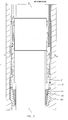
- Figure 1 shows a tubular casing 10 extending through a tubular wellhead 11.
- the casing includes a conventional casing coupling 12.
- the internal surface of the wellhead is formed with a landing shoulder 14.
- Apparatus in accordance with the present invention can be lowered into the annular space between the casing 10 and the wellhead 11.
- This apparatus comprises a tool, shown generally at 15, a slip carrier 16 supported from the tool, and a slip assembly shown generally at 17 which is carried by the slip carrier 16.
- the tool 15 comprises inner and outer relatively movable tubular members 20, 21.
- the upper end portion of the outer tubular member 20 has connected thereto a plurality of angularly spaced eyebolts 22 through which extend cables 24.
- the cables extend up to surface equipment to enable the apparatus to be lowered to the position shown in Figure 1.
- the outer tubular member 20 is also formed with an internal shoulder 26.
- a bore 28 extends axially through the outer tubular member and opens at a position adjacent the shoulder 26.
- the upper end of the bore 28 is connected to a hydraulic supply line which extends upwardly to surface equipment.
- the inner tubular member 21 is formed with an outwardly extending annular portion 30 which defines a shoulder 31 disposed beneath the shoulder 26.
- the shoulders 31 and 26 define a space into which hydraulic fluid can be forced under pressure through the conduit 28. This space is sealed by annular seals 34, 35.
- the lower portion of the outer tubular member 20 is threaded at 38, this thread engaging a similar thread on an upper portion of the slip carrier 16.
- the slip assembly 17 comprises an annular generally wedge-shaped slip bowl 40 which is coupled to the slip carrier 16 by shear pins 41.
- the outer surface of the slip bowl 40 is formed with a shoulder 42 which is shaped to conform with the shoulder 14, formed on the internal surface of the wellhead.
- the slip assembly 17 also comprises a plurality of angularly spaced, generally wedge-shaped slips 44.
- Each slip 44 is coupled to the slip carrier 16 by shear pin 46.
- the shear pins 46 are designed to shear at a shear force which is less than the shear force required to shear the pins 41.
- the inner cylindrical surface of each slip 44 has upwardly facing teeth 45 formed thereon and the outer cylindrical surface has downwardly facing teeth formed thereon.
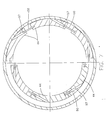
- Figure 7 there are six slips 44 spaced angularly around a central axis.
- the slips are guided by threaded pins 50 which extend between adjacent slips.
- the heads of the pins can slide in bores 57.
- the right hand side of Figure 7 shows the retracted positions of the slips while the left hand side shows the slips after having been moved to their gripping position which will be described below.
- the apparatus In use, the apparatus is lowered into the annular space between the casing 10 and wellhead 11. It will be appreciated that the structure of the apparatus allows it to be lowered past items such as casing coupling 12 and blowout preventers (not shown).
- the apparatus is lowered until the slip bowl 40 becomes landed on the shoulder 14 as shown in Figure 2.
- hydraulic pressure is applied via conduit 28 to the space between the shoulders 31 and 26. This causes a downward force to be applied to the inner tubular member 21 which causes shearing of the pins 46.
- the slips 44 are caused to move downwardly as illustrated in Figure 3.
- the hydraulic pressure causes the slips 44 to become wedged between the casing and the slip bowl 40 as shown in Figure 4 of the drawings.
- the teeth 45 on the slips 44 grip the casing surface.
- the next step is to increase the hydraulic pressure applied between the inner and outer tubular members 21 and 20.
- the inner tubular member 21 cannot move downwardly any further and the increased hydraulic pressure generates an upward force on the outer tubular member 20 which causes shear pins 41 to shear.
- the slip carrier 16 becomes detached from the slip bowl 40 as shown in Figure 5 of the drawings.
- the tool and slip carrier can be retrieved, as illustrated in Figure 6 of the drawings. This completes the location of the slip assembly in the space between the casing and the wellhead so that the casing becomes supported by the wellhead.
- seal assembly can subsequently be located above the slip assembly as will be apparent to those skilled in the art.
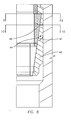
- FIG 8 illustrates an alternative arrangement in which four slips are employed.
Landscapes
- Life Sciences & Earth Sciences (AREA)
- Engineering & Computer Science (AREA)
- Geology (AREA)
- Mining & Mineral Resources (AREA)
- Physics & Mathematics (AREA)
- Environmental & Geological Engineering (AREA)
- Fluid Mechanics (AREA)
- General Life Sciences & Earth Sciences (AREA)
- Geochemistry & Mineralogy (AREA)
- Excavating Of Shafts Or Tunnels (AREA)
- Earth Drilling (AREA)
Applications Claiming Priority (2)
| Application Number | Priority Date | Filing Date | Title |
|---|---|---|---|
| GB8826005 | 1988-11-07 | ||
| GB888826005A GB8826005D0 (en) | 1988-11-07 | 1988-11-07 | Method & apparatus for supporting one tubular member within another |
Publications (2)
| Publication Number | Publication Date |
|---|---|
| EP0368515A1 true EP0368515A1 (fr) | 1990-05-16 |
| EP0368515B1 EP0368515B1 (fr) | 1993-08-18 |
Family
ID=10646423
Family Applications (1)
| Application Number | Title | Priority Date | Filing Date |
|---|---|---|---|
| EP89311104A Expired - Lifetime EP0368515B1 (fr) | 1988-11-07 | 1989-10-27 | Procédé et dispositif pour supporter un élément tubulaire dans un autre |
Country Status (7)
| Country | Link |
|---|---|
| US (1) | US4982795A (fr) |
| EP (1) | EP0368515B1 (fr) |
| JP (1) | JPH02176091A (fr) |
| CA (1) | CA2002373A1 (fr) |
| DE (1) | DE68908526T2 (fr) |
| GB (1) | GB8826005D0 (fr) |
| NO (1) | NO894434L (fr) |
Cited By (2)
| Publication number | Priority date | Publication date | Assignee | Title |
|---|---|---|---|---|
| EP0952304A1 (fr) * | 1998-04-14 | 1999-10-27 | Cooper Cameron Corporation | Assemblage de suspension |
| WO2003048519A1 (fr) * | 2001-11-29 | 2003-06-12 | Weatherford/Lamb, Inc. | Suspension de colonne perdue a expansion et procede d'installation correspondant |
Families Citing this family (19)
| Publication number | Priority date | Publication date | Assignee | Title |
|---|---|---|---|---|
| US5222555A (en) * | 1991-12-13 | 1993-06-29 | Abb Vetco Gray Inc. | Emergency casing hanger system |
| US5301750A (en) * | 1993-01-21 | 1994-04-12 | Dril-Quip, Inc. | Wellhead apparatus |
| DE69701787T2 (de) * | 1996-01-04 | 2000-11-09 | Weatherford/Lamb Inc., Wilmington | Entriegelungsmechanismus |
| GB9722383D0 (en) * | 1997-10-24 | 1997-12-24 | Plexus Ocean Syst Ltd | Clamping well casings |
| US6125939A (en) * | 1998-07-15 | 2000-10-03 | Cooper Cameron Corporation | Remotely deployable landing shoulder |
| US6662868B1 (en) * | 2000-05-03 | 2003-12-16 | Bernard H. Van Bilderbeek | Clamping well casings |
| US6598673B1 (en) * | 1999-10-12 | 2003-07-29 | Abb Vetco Gray Inc. | Wellhead load ring |
| MXPA06005932A (es) | 2001-10-25 | 2007-05-07 | Pleux Ocean Systems Ltd | Entubado de pozo de sujecion. |
| US6834718B2 (en) * | 2001-12-21 | 2004-12-28 | Stream-Flo Industries, Ltd. | Casing head connector with landing base |
| US7900706B2 (en) * | 2004-07-26 | 2011-03-08 | Vetco Gray Inc. | Shoulder ring set on casing hanger trip |
| US8479824B2 (en) * | 2008-10-02 | 2013-07-09 | Weatherford/Lamb, Inc. | Power slip assembly for wellhead casing and wellbore tubing |
| JP5390206B2 (ja) * | 2009-01-28 | 2014-01-15 | 株式会社明間ボーリング | インナーバーレルによって構成されるワイヤーライン方式で用いられるコア採取装置 |
| CA3106627C (fr) * | 2014-03-31 | 2022-11-29 | Fmc Technologies, Inc. | Installation d'un dispositif de suspension coulissante d'un boitier d'urgence et ensemble garniture annulaire comprenant un systeme d'etancheite metal-metal a travers l'obturateur anti-eruption |
| BR102015016971B1 (pt) * | 2014-07-16 | 2022-03-22 | Dril-Quip, Inc | Conjunto de retenção mecânica e método para reter uma coluna de ligação por extensão de poço |
| US9617820B2 (en) | 2015-07-08 | 2017-04-11 | Ge Oil & Gas Pressure Control Lp | Flexible emergency hanger and method of installation |
| US20180112479A1 (en) * | 2016-10-24 | 2018-04-26 | Cameron International Corporation | Apparatus and method for landing and setting slip assembly |
| WO2019018496A1 (fr) * | 2017-07-18 | 2019-01-24 | Ge Oil Gas Pressure Control Lp | Ensemble de suspension de coin de retenue |
| US10590727B1 (en) * | 2019-02-06 | 2020-03-17 | Cameron International Corporation | Hanger system |
| CN112855055B (zh) * | 2019-11-28 | 2022-07-05 | 中国石油天然气股份有限公司 | 筛管送入工具 |
Citations (4)
| Publication number | Priority date | Publication date | Assignee | Title |
|---|---|---|---|---|
| US3011558A (en) * | 1957-12-24 | 1961-12-05 | Baker Oil Tools Inc | Well conduit anchoring apparatus |
| US3206227A (en) * | 1962-03-19 | 1965-09-14 | Fmc Corp | Underwater completion overshot wellhead |
| US4249601A (en) * | 1979-02-06 | 1981-02-10 | White Pat M | Hydraulic running tool for liner hangers |
| US4823871A (en) * | 1988-02-24 | 1989-04-25 | Cameron Iron Works Usa, Inc. | Hanger and seal assembly |
Family Cites Families (7)
| Publication number | Priority date | Publication date | Assignee | Title |
|---|---|---|---|---|
| US3098525A (en) * | 1961-04-27 | 1963-07-23 | Shell Oil Co | Apparatus for installing and retrieving equipment from underwater wells |
| US3468559A (en) * | 1965-10-23 | 1969-09-23 | Ventura Tool Co | Hydraulically actuated casing hanger |
| US3977473A (en) * | 1975-07-14 | 1976-08-31 | Page John S Jr | Well tubing anchor with automatic delay and method of installation in a well |
| CA1057653A (fr) * | 1976-04-29 | 1979-07-03 | Edmund M. Mouret | Outil hydraulique pour la manutention des cuvelages sous-marins |
| NO154703C (no) * | 1983-11-11 | 1986-12-03 | Maritime Hydraulics As | Anordning ved roerhaandteringsinnretning. |
| US4691781A (en) * | 1986-05-28 | 1987-09-08 | Otis Engineering Corporation | Well drilling and completion apparatus |
| US4848462A (en) * | 1988-05-09 | 1989-07-18 | Lindsey Completion Systems, Inc. | Rotatable liner hanger |
-
1988
- 1988-11-07 GB GB888826005A patent/GB8826005D0/en active Pending
-
1989
- 1989-10-27 DE DE89311104T patent/DE68908526T2/de not_active Expired - Fee Related
- 1989-10-27 EP EP89311104A patent/EP0368515B1/fr not_active Expired - Lifetime
- 1989-11-03 US US07/431,521 patent/US4982795A/en not_active Expired - Fee Related
- 1989-11-07 CA CA002002373A patent/CA2002373A1/fr not_active Abandoned
- 1989-11-07 JP JP1289828A patent/JPH02176091A/ja active Pending
- 1989-11-07 NO NO89894434A patent/NO894434L/no unknown
Patent Citations (4)
| Publication number | Priority date | Publication date | Assignee | Title |
|---|---|---|---|---|
| US3011558A (en) * | 1957-12-24 | 1961-12-05 | Baker Oil Tools Inc | Well conduit anchoring apparatus |
| US3206227A (en) * | 1962-03-19 | 1965-09-14 | Fmc Corp | Underwater completion overshot wellhead |
| US4249601A (en) * | 1979-02-06 | 1981-02-10 | White Pat M | Hydraulic running tool for liner hangers |
| US4823871A (en) * | 1988-02-24 | 1989-04-25 | Cameron Iron Works Usa, Inc. | Hanger and seal assembly |
Cited By (5)
| Publication number | Priority date | Publication date | Assignee | Title |
|---|---|---|---|---|
| EP0952304A1 (fr) * | 1998-04-14 | 1999-10-27 | Cooper Cameron Corporation | Assemblage de suspension |
| US6138751A (en) * | 1998-04-14 | 2000-10-31 | Cooper Cameron Corporation | Hanger assembly |
| WO2003048519A1 (fr) * | 2001-11-29 | 2003-06-12 | Weatherford/Lamb, Inc. | Suspension de colonne perdue a expansion et procede d'installation correspondant |
| US6877567B2 (en) | 2001-11-29 | 2005-04-12 | Weatherford/Lamb, Inc. | Expansion set liner hanger and method of setting same |
| GB2396174B (en) * | 2001-11-29 | 2005-10-05 | Weatherford Lamb | Expansion set liner hanger and method of setting same |
Also Published As
| Publication number | Publication date |
|---|---|
| JPH02176091A (ja) | 1990-07-09 |
| DE68908526T2 (de) | 1993-12-02 |
| GB8826005D0 (en) | 1988-12-14 |
| DE68908526D1 (de) | 1993-09-23 |
| CA2002373A1 (fr) | 1990-05-07 |
| EP0368515B1 (fr) | 1993-08-18 |
| NO894434L (no) | 1990-05-08 |
| NO894434D0 (no) | 1989-11-07 |
| US4982795A (en) | 1991-01-08 |
Similar Documents
| Publication | Publication Date | Title |
|---|---|---|
| EP0368515B1 (fr) | Procédé et dispositif pour supporter un élément tubulaire dans un autre | |
| US4736799A (en) | Subsea tubing hanger | |
| US4540053A (en) | Breech block hanger support well completion method | |
| US4615544A (en) | Subsea wellhead system | |
| US4836288A (en) | Casing hanger and packoff running tool | |
| US5988287A (en) | Thru-tubing anchor seal assembly and/or packer release devices | |
| US4880061A (en) | Tool for running structures in a well | |
| US4757860A (en) | Wellhead equipment | |
| US3137348A (en) | Apparatus and method for drilling and completing a well | |
| US4595063A (en) | Subsea casing hanger suspension system | |
| US4422507A (en) | Wellhead apparatus | |
| US4674576A (en) | Casing hanger running tool | |
| US4842061A (en) | Casing hanger packoff with C-shaped metal seal | |
| US5671812A (en) | Hydraulic pressure assisted casing tensioning system | |
| US5069288A (en) | Single trip casing hanger/packoff running tool | |
| EP3563027B1 (fr) | Ensembles d'outil de pose et procédés | |
| US5638903A (en) | Adjustable mandrel hanger system | |
| US5209521A (en) | Expanding load shoulder | |
| US7134490B2 (en) | Through bore wellhead hanger system | |
| US4995458A (en) | Wear bushing retrieval tool | |
| US4565247A (en) | Wireline set tubing retrievable seal bore packer apparatus | |
| NO20200128A1 (en) | Slip hanger assembly | |
| GB2114631A (en) | Breech block hanger support | |
| EP0391541B1 (fr) | Outil pour la récupération d'une douille de protection contre l'usure | |
| GB2308168A (en) | Adjustable casing hanger |
Legal Events
| Date | Code | Title | Description |
|---|---|---|---|
| PUAI | Public reference made under article 153(3) epc to a published international application that has entered the european phase |
Free format text: ORIGINAL CODE: 0009012 |
|
| AK | Designated contracting states |
Kind code of ref document: A1 Designated state(s): DE FR GB NL |
|
| 17P | Request for examination filed |
Effective date: 19901017 |
|
| RAP1 | Party data changed (applicant data changed or rights of an application transferred) |
Owner name: COOPER INDUSTRIES INC. |
|
| 17Q | First examination report despatched |
Effective date: 19920129 |
|
| GRAA | (expected) grant |
Free format text: ORIGINAL CODE: 0009210 |
|
| AK | Designated contracting states |
Kind code of ref document: B1 Designated state(s): DE FR GB NL |
|
| REF | Corresponds to: |
Ref document number: 68908526 Country of ref document: DE Date of ref document: 19930923 |
|
| ET | Fr: translation filed | ||
| PLBE | No opposition filed within time limit |
Free format text: ORIGINAL CODE: 0009261 |
|
| STAA | Information on the status of an ep patent application or granted ep patent |
Free format text: STATUS: NO OPPOSITION FILED WITHIN TIME LIMIT |
|
| 26N | No opposition filed | ||
| PGFP | Annual fee paid to national office [announced via postgrant information from national office to epo] |
Ref country code: DE Payment date: 19951027 Year of fee payment: 7 |
|
| REG | Reference to a national code |
Ref country code: GB Ref legal event code: 732E |
|
| PGFP | Annual fee paid to national office [announced via postgrant information from national office to epo] |
Ref country code: FR Payment date: 19961011 Year of fee payment: 8 |
|
| PG25 | Lapsed in a contracting state [announced via postgrant information from national office to epo] |
Ref country code: DE Effective date: 19970701 |
|
| PG25 | Lapsed in a contracting state [announced via postgrant information from national office to epo] |
Ref country code: FR Free format text: THE PATENT HAS BEEN ANNULLED BY A DECISION OF A NATIONAL AUTHORITY Effective date: 19971031 |
|
| REG | Reference to a national code |
Ref country code: FR Ref legal event code: ST |
|
| REG | Reference to a national code |
Ref country code: GB Ref legal event code: IF02 |
|
| PGFP | Annual fee paid to national office [announced via postgrant information from national office to epo] |
Ref country code: NL Payment date: 20020919 Year of fee payment: 14 |
|
| PG25 | Lapsed in a contracting state [announced via postgrant information from national office to epo] |
Ref country code: NL Free format text: LAPSE BECAUSE OF NON-PAYMENT OF DUE FEES Effective date: 20040501 |
|
| NLV4 | Nl: lapsed or anulled due to non-payment of the annual fee |
Effective date: 20040501 |
|
| PGFP | Annual fee paid to national office [announced via postgrant information from national office to epo] |
Ref country code: GB Payment date: 20080915 Year of fee payment: 20 |
|
| REG | Reference to a national code |
Ref country code: GB Ref legal event code: PE20 Expiry date: 20091026 |
|
| PG25 | Lapsed in a contracting state [announced via postgrant information from national office to epo] |
Ref country code: GB Free format text: LAPSE BECAUSE OF EXPIRATION OF PROTECTION Effective date: 20091026 |