EP0368525A1 - Procédé et dispositif de génération d'inversion de population en vue de l'émission stimulée - Google Patents
Procédé et dispositif de génération d'inversion de population en vue de l'émission stimulée Download PDFInfo
- Publication number
- EP0368525A1 EP0368525A1 EP89311149A EP89311149A EP0368525A1 EP 0368525 A1 EP0368525 A1 EP 0368525A1 EP 89311149 A EP89311149 A EP 89311149A EP 89311149 A EP89311149 A EP 89311149A EP 0368525 A1 EP0368525 A1 EP 0368525A1
- Authority
- EP
- European Patent Office
- Prior art keywords
- gas
- nozzle
- electronic state
- laser
- energy
- Prior art date
- Legal status (The legal status is an assumption and is not a legal conclusion. Google has not performed a legal analysis and makes no representation as to the accuracy of the status listed.)
- Withdrawn
Links
- 238000000034 method Methods 0.000 title claims abstract description 26
- 239000012141 concentrate Substances 0.000 claims abstract description 9
- 230000004936 stimulating effect Effects 0.000 claims abstract description 3
- 239000007789 gas Substances 0.000 claims description 75
- 230000005284 excitation Effects 0.000 claims description 12
- 229910052756 noble gas Inorganic materials 0.000 claims description 11
- 150000002835 noble gases Chemical class 0.000 claims description 11
- 230000005855 radiation Effects 0.000 claims description 8
- 230000000694 effects Effects 0.000 claims description 5
- 230000007704 transition Effects 0.000 claims description 5
- IJGRMHOSHXDMSA-UHFFFAOYSA-N Atomic nitrogen Chemical compound N#N IJGRMHOSHXDMSA-UHFFFAOYSA-N 0.000 claims description 4
- CURLTUGMZLYLDI-UHFFFAOYSA-N Carbon dioxide Chemical compound O=C=O CURLTUGMZLYLDI-UHFFFAOYSA-N 0.000 claims description 4
- 239000010453 quartz Substances 0.000 claims description 4
- VYPSYNLAJGMNEJ-UHFFFAOYSA-N silicon dioxide Inorganic materials O=[Si]=O VYPSYNLAJGMNEJ-UHFFFAOYSA-N 0.000 claims description 4
- 230000003321 amplification Effects 0.000 claims description 3
- 229910001092 metal group alloy Inorganic materials 0.000 claims description 3
- 238000003199 nucleic acid amplification method Methods 0.000 claims description 3
- UGFAIRIUMAVXCW-UHFFFAOYSA-N Carbon monoxide Chemical compound [O+]#[C-] UGFAIRIUMAVXCW-UHFFFAOYSA-N 0.000 claims description 2
- 229910002092 carbon dioxide Inorganic materials 0.000 claims description 2
- 239000001569 carbon dioxide Substances 0.000 claims description 2
- 229910002091 carbon monoxide Inorganic materials 0.000 claims description 2
- 239000000919 ceramic Substances 0.000 claims description 2
- 150000004820 halides Chemical class 0.000 claims description 2
- 150000004678 hydrides Chemical class 0.000 claims description 2
- 229910052751 metal Inorganic materials 0.000 claims description 2
- 239000002184 metal Substances 0.000 claims description 2
- 229910001507 metal halide Inorganic materials 0.000 claims description 2
- 150000005309 metal halides Chemical class 0.000 claims description 2
- 150000002739 metals Chemical class 0.000 claims description 2
- 229910052757 nitrogen Inorganic materials 0.000 claims description 2
- 229910052594 sapphire Inorganic materials 0.000 claims description 2
- 239000010980 sapphire Substances 0.000 claims description 2
- 238000011144 upstream manufacturing Methods 0.000 claims 1
- XKRFYHLGVUSROY-UHFFFAOYSA-N Argon Chemical compound [Ar] XKRFYHLGVUSROY-UHFFFAOYSA-N 0.000 description 26
- 229910052786 argon Inorganic materials 0.000 description 14
- 238000001816 cooling Methods 0.000 description 10
- 230000005283 ground state Effects 0.000 description 7
- 238000010894 electron beam technology Methods 0.000 description 6
- 238000002474 experimental method Methods 0.000 description 4
- 238000001228 spectrum Methods 0.000 description 4
- 230000001427 coherent effect Effects 0.000 description 3
- 239000000463 material Substances 0.000 description 3
- PXGOKWXKJXAPGV-UHFFFAOYSA-N Fluorine Chemical compound FF PXGOKWXKJXAPGV-UHFFFAOYSA-N 0.000 description 2
- 238000001069 Raman spectroscopy Methods 0.000 description 2
- 230000003466 anti-cipated effect Effects 0.000 description 2
- 239000012535 impurity Substances 0.000 description 2
- 230000003287 optical effect Effects 0.000 description 2
- OKTJSMMVPCPJKN-UHFFFAOYSA-N Carbon Chemical compound [C] OKTJSMMVPCPJKN-UHFFFAOYSA-N 0.000 description 1
- HCHKCACWOHOZIP-UHFFFAOYSA-N Zinc Chemical compound [Zn] HCHKCACWOHOZIP-UHFFFAOYSA-N 0.000 description 1
- 229910052782 aluminium Inorganic materials 0.000 description 1
- XAGFODPZIPBFFR-UHFFFAOYSA-N aluminium Chemical compound [Al] XAGFODPZIPBFFR-UHFFFAOYSA-N 0.000 description 1
- 238000004458 analytical method Methods 0.000 description 1
- ISQINHMJILFLAQ-UHFFFAOYSA-N argon hydrofluoride Chemical compound F.[Ar] ISQINHMJILFLAQ-UHFFFAOYSA-N 0.000 description 1
- QVGXLLKOCUKJST-UHFFFAOYSA-N atomic oxygen Chemical compound [O] QVGXLLKOCUKJST-UHFFFAOYSA-N 0.000 description 1
- 229910052793 cadmium Inorganic materials 0.000 description 1
- BDOSMKKIYDKNTQ-UHFFFAOYSA-N cadmium atom Chemical compound [Cd] BDOSMKKIYDKNTQ-UHFFFAOYSA-N 0.000 description 1
- 229910052799 carbon Inorganic materials 0.000 description 1
- 150000001793 charged compounds Chemical class 0.000 description 1
- 230000002517 constrictor effect Effects 0.000 description 1
- 230000001419 dependent effect Effects 0.000 description 1
- 238000000295 emission spectrum Methods 0.000 description 1
- 229910052731 fluorine Inorganic materials 0.000 description 1
- 239000011737 fluorine Substances 0.000 description 1
- 229910052734 helium Inorganic materials 0.000 description 1
- 230000003993 interaction Effects 0.000 description 1
- 230000002427 irreversible effect Effects 0.000 description 1
- QSHDDOUJBYECFT-UHFFFAOYSA-N mercury Chemical compound [Hg] QSHDDOUJBYECFT-UHFFFAOYSA-N 0.000 description 1
- 229910052753 mercury Inorganic materials 0.000 description 1
- 238000001393 microlithography Methods 0.000 description 1
- 239000001301 oxygen Substances 0.000 description 1
- 229910052760 oxygen Inorganic materials 0.000 description 1
- 210000002381 plasma Anatomy 0.000 description 1
- 230000002040 relaxant effect Effects 0.000 description 1
- 230000000717 retained effect Effects 0.000 description 1
- 230000002441 reversible effect Effects 0.000 description 1
- HBMJWWWQQXIZIP-UHFFFAOYSA-N silicon carbide Chemical compound [Si+]#[C-] HBMJWWWQQXIZIP-UHFFFAOYSA-N 0.000 description 1
- 229910010271 silicon carbide Inorganic materials 0.000 description 1
- 238000004611 spectroscopical analysis Methods 0.000 description 1
- 239000000126 substance Substances 0.000 description 1
- 229910052724 xenon Inorganic materials 0.000 description 1
- 229910052725 zinc Inorganic materials 0.000 description 1
- 239000011701 zinc Substances 0.000 description 1
Images

Classifications
-
- H—ELECTRICITY
- H01—ELECTRIC ELEMENTS
- H01S—DEVICES USING THE PROCESS OF LIGHT AMPLIFICATION BY STIMULATED EMISSION OF RADIATION [LASER] TO AMPLIFY OR GENERATE LIGHT; DEVICES USING STIMULATED EMISSION OF ELECTROMAGNETIC RADIATION IN WAVE RANGES OTHER THAN OPTICAL
- H01S3/00—Lasers, i.e. devices using stimulated emission of electromagnetic radiation in the infrared, visible or ultraviolet wave range
- H01S3/09—Processes or apparatus for excitation, e.g. pumping
- H01S3/097—Processes or apparatus for excitation, e.g. pumping by gas discharge of a gas laser
- H01S3/0979—Gas dynamic lasers, i.e. with expansion of the laser gas medium to supersonic flow speeds
-
- H—ELECTRICITY
- H01—ELECTRIC ELEMENTS
- H01S—DEVICES USING THE PROCESS OF LIGHT AMPLIFICATION BY STIMULATED EMISSION OF RADIATION [LASER] TO AMPLIFY OR GENERATE LIGHT; DEVICES USING STIMULATED EMISSION OF ELECTROMAGNETIC RADIATION IN WAVE RANGES OTHER THAN OPTICAL
- H01S3/00—Lasers, i.e. devices using stimulated emission of electromagnetic radiation in the infrared, visible or ultraviolet wave range
- H01S3/14—Lasers, i.e. devices using stimulated emission of electromagnetic radiation in the infrared, visible or ultraviolet wave range characterised by the material used as the active medium
- H01S3/22—Gases
- H01S3/223—Gases the active gas being polyatomic, i.e. containing two or more atoms
- H01S3/225—Gases the active gas being polyatomic, i.e. containing two or more atoms comprising an excimer or exciplex
Definitions
- This invention relates to the generation of inverted populations for stimulated emission generation, lasers and other devices. More particularly, it relates to lasers using gaseous media of excimers and exciplexes, and generally to lasers having emissions from bound-to-free states.
- Lasers operating in the VUV region are desired for use in scientific studies of the interaction between radiation and matter, as a source to optically pump other lasers and for a variety of techniques, such as surface probing, microlithography and biological studies.
- intense coherent radiation in this region is necessary to measure the densities of impurities such as carbon and oxygen in plasmas in at least one of the techniques employed today.
- the shortest wavelengths in readily available lasers are those of excimer lasers using argon-fluoride (ArF) gas. With fluorine (F2) gas these lasers reach wavelengths of 156 nm, however operation with this gas is difficult and few are in use.
- the shortest wavelength in common use with ArF gas is 193 nm.
- An argon excimer laser has emissions of approximately 126 nm.
- the first such laser employed an electron beam as the exciting energy.
- the laser had a great deal of power, but the electron accelerator is the size of a small room and the laser itself is half that size.
- the electron beam excites only a relatively small number of the argon atoms due to the narrow width of the beam compared to the gas volume.
- the only laser in use today is an electron-beam diode with a 700 kV and 5 kJ input power source.
- the lasing effect of the argon excimer laser is produced by emissions from excited Ar2 molecules, denoted with an * from now on, as opposed to excited Ar atoms, Ar*.
- Ar2* molecules are not naturally occurring.
- the molecules must be created by collisions between separate atoms. A large gas volume is used in the laser to create the desired number of emissions and generate the resulting power. The collisions are encouraged by keeping the gas under a great deal of pressure, approximately 10 atmospheres.
- the exciting electron beam of the argon excimer laser produces Ar2* molecules of varying energy levels.
- the populations in these energy levels are not artificially concentrated and result in emissions from each of the energy levels. This produces light of different wavelengths or broad band width. In order to produce coherent light of shorter wavelength the resulting emissions must be shifted by anti-Stokes Raman scattering with a resulting loss in overall power and efficiency.
- a technique for concentrating excited molecules into fewer energy levels with excitation by a gas discharge This technique is called relaxation by supersonic expansion cooling and has been used to cool, mainly rotationally, and also vibrationally, various molecules, including NO and ND4, and OH radicals. It was developed in order to analyze the spectra of excited and relaxed molecules and radicals which were not previously able to be analyzed. (Chemical Physics Letters; Vol. 113, Number 2, pages 129-134; Emission Spectra in a Supersonic Expansion; Huber and Sears). Authors of papers studying these types of spectra mentioned above have used the absorptive spectra in their analysis which are undesirable in lasing systems.
- a method of producing an inverted population in a gas comprising exciting the gas at one pressure so as to give a portion of the gas the energy of a higher electronic state, expanding the gas to a second lower pressure, so as to concentrate said portion of the gas into a reduced number of energy levels in the higher electronic state, whereby a population inversion is produced between the higher electronic state and a lower electronic state.
- the gas will be excited into a range of energy levels, that is a range of both vibrational and rotational energy levels in the higher electronic state.
- the gas portion could be excited into just one vibrational energy level in the higher state.
- the gas is excited by an electronic discharge, and cooling is effected by supersonic expansion through a nozzle or the like.
- the present invention is based on the realization that supersonic cooling in a nozzle, or an equivalent cooling technique, can be used to concentrate the populations into a few energy levels. This can then generate the required population inversion.
- the present invention also provides a method of producing stimulated emission in a gas, comprising:
- the present invention further provides an apparatus for producing stimulated emission, the apparatus comprising: an inlet for pressurized gas; an excitation source, for electronically exciting gas to give a portion of the gas the energy levels of a higher electronic state; means for expanding and cooling the gas to concentrate said portion of the gas into a reduced number of energy levels in the higher electronic state, and hence cause a population inversion relative to a lower electronic state; and means for causing stimulated emission and amplification of the excited and cooled gas, by transition from the higher electronic state to the lower electronic state.
- the stimulated emission can occur in an amplifier or the like.
- the stimulated emission can occur in a laser cavity, equipped with mirrors in a manner such that the apparatus would then function as a laser.
- a very low pressure eg. around 1 mTorr will be necessary.
- the laser cavity it is not necessary for the laser cavity to be within the low pressure region.
- the mechanical and optical components of the laser cavity can be outside the low pressure region. It is only necessary that the principal axis of the cavity pass through the region of gain, ie. the region immediately downstream from the nozzle where the stimulated emission occurs.
- Argon is particularly well suited to producing such an inversion.
- Ar2 has an unstable ground state as shown in fig. 1.
- the independent axis is the internuclear distance between respective Ar atoms, while the dependent axis is the energy of the atoms.
- a lower curve 1 represents the ground state energy.
- a middle curve 3 represents the first excited electronic state energy.
- An upper curve 5, shown in dashed outline, represents the upper electronic energy states.
- Each curve 1,3,5 has a well portion 7,9,11 respectively and a flat portion 13,15,17 respectively. When an Ar atom is in a well portion 7,9 or 11 it is part of an Ar2 molecule. When an Ar atom is in a flat portion it is a separate atom.
- the well 7 is far more shallow than the other wells 9,11.
- An Ar2 molecule in the well 7 requires very little additional energy to split into separate Ar atoms. A simple collision with a container which confines the Ar2 molecule will split the atoms. This means very few Ar2 molecules will populate the well 7.
- the inventors have further examined the energy curves 1,3,5 and discovered a storage energy level at the bottom of the well 9.
- the lines 9a,9b,9c,9d in the well 9 represent a number of different rotational and vibrational energy levels within the electronic state 3. These lines 9a,9b,9c,9d do not represent all of the energy levels, but will serve to illustrate the phenomena discovered.
- the lines 9a-9d have an interesting characteristic. Ar2* in the lowest energy level 9a of the well 9 will take longer to decay than the Ar2* atoms in the other states 9b,9c,9d.
- the storage time is approximately 3 microseconds. This means a process relaxing (cooling) the Ar2* in the energy levels within the storage time of the Ar2* of line 9a will concentrate the Ar2* to substantially one energy level 9a for the well 9.
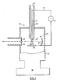
- the laser 19 has a conduit 21, an exciter 23 and a laser cavity 25.
- the conduit 21 has a gas input 27 and a nozzle 29.
- the conduit 21 the inventors employed in experiments was constructed of quartz.
- the diameter of the quartz in the conduit was approximately 1 cm.
- the nozzle 29 was approximately 300 microns in diameter.
- the exciter 23 combines a voltage source 31 with a first electrode 33 and a second electrode 35.
- the exciter 23 shown in the preferred embodiment is a discharge energy source 23.
- the electrode 33 is a wire filament 33 in the conduit 21.
- the tip of electrode 33 is close to the nozzle 29.
- the electrode 35, the nozzle 29 and the cavity 25 are enclosed in a chamber 41 which is connected to a vacuum pump 36 (indicated schematically).
- the cavity 25 lies near the conduit 21 beyond the nozzle 29.
- the electrode 35 is 15 mm below the nozzle 29.
- the cavity 25 has a first concave mirror 37 and a second flat mirror 39 as is known in the art.
- the cavity 25 may be more sophisticated to provide tuning where necessary via a prism or grating or other such refinements.
- the cavity 25 shown is the most rudimentary to explain the concepts.
- argon gas at approximately 1 atm is fed into the input 27.
- the pump 36 draws the gas through the conduit 21 and the container and maintains a very low pressure, of approximately 1 mTorr, in the chamber 41.
- the voltage source 31 is switched to create a discharge between the electrodes 33,35.
- the electrode 33 is sufficiently close to the nozzle 29 to allow the discharge to take place.
- the discharge imparts excitation energy into the gas to excite Ar atoms in the conduit 21 near the nozzle 29 to Ar*.
- the Ar* are slowed by the funnelling and constricting effect in the nozzle 29.
- the Ar* collide with unexcited Argon atoms, Ar, and combine to form Ar2*.
- Almost all of the Ar2* are vibrationally cooled by the time they pass through the nozzle 29, and rotationally cooled on expansion in the evacuated chamber 41. This puts the Ar2* into the well 9 or into the well 11 of fig. 1.
- the Ar2* would decay after their storage time has elapsed. The storage time is sufficient to allow the cooled Ar2* out of the nozzle 29, but not long enough for the fig.
- the Ar2* to disperse and lose added power their density can give.
- the electrode 33 is also sufficiently close to the nozzle 29 for the Ar 2* to not decay prior to leaving the nozzle 29.
- Emissions occur during the storage time and are in all directions.
- the emissions close to the perpendicular to the axis of the conduit 21 are caught by the laser cavity 25 as is known in the art and reflected between the mirrors 37,39.
- the mirror 39 is provided with a central opening 40. The intention is that radiation will be captured by the mirrors 37, 39 and output through the opening 40.
- the cavity 25 must, of course be near enough to the nozzle (approx. 5 mm) for a substantial number of Ar2* to be within the cavity 25 prior to their decay.
- the reflected emissions stimulate further coherent emissions from the Ar2* as they pass by the nozzle 29 and into the volume of the laser cavity 25.
- Increases in pressure in the conduit 21 are possible using stronger and/or thicker materials. Increased pressures create greater collisions at the nozzle 29 and more Ar2*. It is noted that cooling depends on the pressure ratio across the nozzle 29. Consequently, if the pressure in the chamber 41 is increased, this could cause a significant increase in the pressure required at the input 27.
- the substantial vacuum created by the pump 36 also serves to prevent the emitted light from being absorbed by impurities in the cavity 25. This allows the laser 19 to be operated continuously for greater periods of time. As well, it is expected that the laser 19 is particularly well suited to operation for scientific experiments in space. In this case, the chamber 41 is no longer necessary.
- the electrode 35 could be positioned inside the conduit 21 alongside the electrode 33, and the container 41 would be retained in its original position. The discharge would then take place between the electrodes 33, 35 fully inside the nozzle 29.
- the exciter 23 could take the form of a non-discharge energy source, not shown, such as an electron beam. Of course some of the size advantages of the preferred embodiment may be lost thereby.
- the intensity of the light increases with the voltage at the source 31.
- the intensity increases more rapidly around the 8 kV mark.
- Experiments have been conducted at up to 20 kV to date. It appears much of the energy from the source is going into the discharge below the 8 kV.
- the intensity of the light will not increase without bound. At higher voltage levels energy will go into ionization of the atoms and light intensity will decrease.
- molecular ions may also be formed in excited electronic states, with population inversion, and provide stimulated emission at other wavelengths.
- a test laser 19 having the parameters discussed herein was operated under pulse operation. The laser effect was achieved.
- the mirrors 37,39 were coated with aluminum. The mirrors were later examined, and from burn damage they received, it is estimated that there was generated an energy density of over 100 mJ/cm2. This is very powerful considering the small volume of gas used. Mirrors with higher energy thresholds, such as silicon carbide should be able to handle the energy density levels for longer periods.
- the laser 19 can be extremely compact and can have a size approximately as shown. Whilst the vacuum pump, voltage source, gas tanks, regulators, etc., will take up some space. It will still be considerably more compact than the Argon excimer loser utilizing electron beam excitation, mentioned above.
- the laser 19 can be arranged to operate either continuously or pulsed. When it is pulsed, at frequencies in the range of 1-5 Hz, both the voltage source 31 and gas supply to the gas input 27 are pulsed.
- the conduit 21 can be stretched so the nozzle 29 takes the form of a slit.
- the first electrode 33 would be similarly stretched, or a number of electrodes provided across the nozzle 29.
- a series of such conduits 21 could be used.
- Each conduit 21 would have a slot-shaped nozzle 29 with the nozzles 29 disposed in a row or several rows parallel to the laser cavity 25 and with the slots aligned for maximum efficiency.
- the inventors have studied energy curves for the other noble gases; He, Ne, Kr and Xe. The curves take on a similar form to those of fig. 1. These gases should lase using a laser 19. The excitation voltage will be lesser or greater depending on the gas used. The inventors have performed experiments for Ne similar to those described for Ar with the predicted results.
- the respective first electronic state to ground state emissions for the other noble gases occur at approximately 50 nm, 71 nm, 146 nm and 176 nm. Higher state to ground state emissions may produce even shorter wavelengths.
- the pressure differential or ratio across the nozzle 29 can be varied to give the desire degree of cooling.
- the voltage between the electrodes 33,35, and hence the field in the discharge can be varied to meet the desired discharge characteristics. In general, these parameters will be different from those used for the earlier technique for spectroscopic analysis. Thus, in order to give a substantial portion of the gas a higher electronic energy level, a higher voltage or field would be used. The earlier technique did not use a voltage or field sufficiently high to give this effect.
- excitation sources can be used.
- an electronic beam or an optical source could be used, instead of an electrical discharge.
- the described apparatus is intended primarily for pulsed operation, it can be operated on a continuous basis. For high power levels, the nozzle tip could be cooled.
- the conduit 21 forming the nozzle 29 can be formed from ceramic, quartz, sapphire, or a hard metal alloy, for example. Where a metal alloy is used, it could form one of the electrodes. Appropriate materials would be used for the mirrors and windows of the system.
- a second nozzle can be provided facing the first nozzle 29.
- One nozzle would then form an anode and the other nozzle a cathode, thereby eliminating the necessity for a separate electrode.
- nozzles of various shapes and configurations can be provided.
- the nozzles could be provided as slots or holes in a variety of patterns.
- nozzles arranged as slots aligned with the axis of the laser cavity will be particularly suitable.
- excimers and exciplexes ie gases having ground state 7
- gases are, halides of the noble gases: hydrides of the noble gases; oxides of the noble gases; alkalis of the noble gases; metals, eg. mercury, cadmium, zinc, etc.; and metal halides.
- the laser system should be usable with a variety of polyatomic excimers and exciplexes. It is also anticipated that the system could be used to rotationally cool presently known laser gases, such as nitrogen, carbon monoxide and carbon dioxide, and thus to concentrate population in fewer energy levels, leading to more powerful output and greater efficiency.
- the method of the present invention can be used for a variety of laser devices.
- it could be used in Raman lasers, Q-switched lasers, mode-locked lasers, etc. It could also be used for a variety of amplifiers.
- the mirrors could alternatively be located outside the cavity with the cavity having transparent walls.
Landscapes
- Physics & Mathematics (AREA)
- Electromagnetism (AREA)
- Engineering & Computer Science (AREA)
- Plasma & Fusion (AREA)
- Optics & Photonics (AREA)
- Fluid Mechanics (AREA)
- Lasers (AREA)
Applications Claiming Priority (2)
| Application Number | Priority Date | Filing Date | Title |
|---|---|---|---|
| CA581441 | 1988-10-27 | ||
| CA581441 | 1988-10-27 |
Publications (1)
| Publication Number | Publication Date |
|---|---|
| EP0368525A1 true EP0368525A1 (fr) | 1990-05-16 |
Family
ID=4138983
Family Applications (1)
| Application Number | Title | Priority Date | Filing Date |
|---|---|---|---|
| EP89311149A Withdrawn EP0368525A1 (fr) | 1988-10-27 | 1989-10-27 | Procédé et dispositif de génération d'inversion de population en vue de l'émission stimulée |
Country Status (2)
| Country | Link |
|---|---|
| EP (1) | EP0368525A1 (fr) |
| WO (1) | WO1990004866A1 (fr) |
Families Citing this family (3)
| Publication number | Priority date | Publication date | Assignee | Title |
|---|---|---|---|---|
| DE4213879A1 (de) * | 1992-04-28 | 1993-11-04 | Bosch Gmbh Robert | Kommunikationssystem zur datenuebertragung von einem bewegten fahrzeug auf eine ortsfeste bake |
| DE4213881A1 (de) * | 1992-04-28 | 1993-11-04 | Bosch Gmbh Robert | System zur bidirektionalen datenuebertragung zwischen einer bake und einem fahrzeug |
| DE4213882A1 (de) * | 1992-04-28 | 1993-11-04 | Bosch Gmbh Robert | Vorrichtung eines fahrzeugs zur datenuebertragung auf eine ortsfeste bake und damit gebildetes kommunikationssystem |
Family Cites Families (1)
| Publication number | Priority date | Publication date | Assignee | Title |
|---|---|---|---|---|
| US4011521A (en) * | 1967-02-16 | 1977-03-08 | Avco Corporation | High powered laser |
-
1989
- 1989-02-24 WO PCT/US1989/000690 patent/WO1990004866A1/fr not_active Ceased
- 1989-10-27 EP EP89311149A patent/EP0368525A1/fr not_active Withdrawn
Non-Patent Citations (6)
| Title |
|---|
| JOURNAL CHEMICAL PHYSICS, vol. 89, no. 5, September 1988, pages 2609-2614; D. FRYE et al.: "Vibration-rotation spectroscopy by stimulated emission pumping in a supersonic beam: a-Axis coriolls coupled v4=1 and v8=1 levels of y1Ag glyoxal" * |
| OPT. SPECTROSC. (USSR), vol. 62, no. 2, February 1987, pages 145-147; M.F. VERESH et al.: "Negative absorption at the 812.6-nm atomic lithium line in a continuous He-Li plasma jet" * |
| REV. SCI. INSTRUM., vol. 58, no. 5, May 1987, pages 812-816; K.H.C. BALDWIN et al.: "Inert gas excimer radiation from a free jet expansion" * |
| SOV. J. QUANTUM ELECTRON, vol. 12, no. 2, February 1982, pages 161-167; N.S. BELOKRINITSKII et al.: "Prelasing investigations of recombination of chlorine atoms" * |
| SOV. J. QUANTUM ELECTRON., vol. 8, no. 12, December 1978, pages 1444-1449; A.B. BASHKIN et al.: "Utilization of excited atoms in thermally initiated chemcial lasers in the visible range" * |
| SOV. TECH. PHYS. LETT., vol. 12, no. 5, May 1986, pages 241-250; V.S. ROGULICH et al.: "Emission by KrF and YeF excimers in a plasma jet" * |
Also Published As
| Publication number | Publication date |
|---|---|
| WO1990004866A1 (fr) | 1990-05-03 |
Similar Documents
| Publication | Publication Date | Title |
|---|---|---|
| US4088965A (en) | Charge transfer reaction laser with preionization means | |
| Wang et al. | Fast‐discharge‐initiated XeF laser | |
| US4414671A (en) | Collision laser | |
| Manuccia et al. | 14‐and 16‐μ gasdynamic CO2 lasers | |
| US5682400A (en) | Supersonic and subsonic laser with high frequency discharge excitation | |
| Sarjeant et al. | A scalable multiatmosphere high‐power XeF laser | |
| EP0054429B1 (fr) | Méthode pour la synchronisation de la radiation Raman diffusée | |
| US4053852A (en) | Method and apparatus for generating coherent near 14 and near 16 micron radiation | |
| EP0368525A1 (fr) | Procédé et dispositif de génération d'inversion de population en vue de l'émission stimulée | |
| US4344174A (en) | Gas lasers | |
| Fahlen | High‐pulse‐rate 10‐W KrF laser | |
| JPS63171640A (ja) | エキシマの形成方法と装置およびレーザへの応用 | |
| EP0015682B1 (fr) | Tube Raman | |
| Biswas et al. | Repetitive transversely excited gas laser pulsers | |
| US4225831A (en) | CW Scalable donor-acceptor gas transfer laser | |
| Goldman | Laser history and theory | |
| Witteman | High power pulsed gas lasers | |
| Soldatov | Multiple-wavelength nanosecond gas-vapor lasers: experiments and applications | |
| Mineev et al. | Microwave Pumped Multi-Frequency Planar Mid-IR Lasers | |
| Quel et al. | C02 LASERS: PHYSICS, TECHNOLOGY AND APPLICATIONS | |
| McClung Jr et al. | Operation of a Transverse Mode‐Controlled Hydrogen Stokes Laser Oscillator | |
| McLeary | Operation of a CO 2 mixing laser at atmospheric pressure | |
| Petukhov et al. | Investigation of the output parameters of a transversely excited CO2 laser in the wavelength range 4.2–4.5 μm (1001–1000 band) | |
| Sze | Inductively stabilized excimer lasers | |
| Kirkici | Electronic Energy Transfer Laser |
Legal Events
| Date | Code | Title | Description |
|---|---|---|---|
| PUAI | Public reference made under article 153(3) epc to a published international application that has entered the european phase |
Free format text: ORIGINAL CODE: 0009012 |
|
| AK | Designated contracting states |
Kind code of ref document: A1 Designated state(s): AT BE CH DE ES FR GB GR IT LI LU NL SE |
|
| STAA | Information on the status of an ep patent application or granted ep patent |
Free format text: STATUS: THE APPLICATION IS DEEMED TO BE WITHDRAWN |
|
| 18D | Application deemed to be withdrawn |
Effective date: 19901117 |