EP0368636B1 - Système de commande hydraulique - Google Patents
Système de commande hydraulique Download PDFInfo
- Publication number
- EP0368636B1 EP0368636B1 EP89311554A EP89311554A EP0368636B1 EP 0368636 B1 EP0368636 B1 EP 0368636B1 EP 89311554 A EP89311554 A EP 89311554A EP 89311554 A EP89311554 A EP 89311554A EP 0368636 B1 EP0368636 B1 EP 0368636B1
- Authority
- EP
- European Patent Office
- Prior art keywords
- pressure
- hole
- balance piston
- valve
- pump
- Prior art date
- Legal status (The legal status is an assumption and is not a legal conclusion. Google has not performed a legal analysis and makes no representation as to the accuracy of the status listed.)
- Expired - Lifetime
Links
- 230000002093 peripheral effect Effects 0.000 claims description 31
- 238000001514 detection method Methods 0.000 claims description 23
- 238000011144 upstream manufacturing Methods 0.000 claims description 16
- 230000007423 decrease Effects 0.000 claims description 15
- 239000012530 fluid Substances 0.000 claims description 7
- 238000010276 construction Methods 0.000 description 13
- 230000013011 mating Effects 0.000 description 6
- 230000007935 neutral effect Effects 0.000 description 6
- 230000003247 decreasing effect Effects 0.000 description 5
- 230000007246 mechanism Effects 0.000 description 4
- NAWXUBYGYWOOIX-SFHVURJKSA-N (2s)-2-[[4-[2-(2,4-diaminoquinazolin-6-yl)ethyl]benzoyl]amino]-4-methylidenepentanedioic acid Chemical compound C1=CC2=NC(N)=NC(N)=C2C=C1CCC1=CC=C(C(=O)N[C@@H](CC(=C)C(O)=O)C(O)=O)C=C1 NAWXUBYGYWOOIX-SFHVURJKSA-N 0.000 description 1
- 230000006835 compression Effects 0.000 description 1
- 238000007906 compression Methods 0.000 description 1
- 238000010586 diagram Methods 0.000 description 1
- 230000004048 modification Effects 0.000 description 1
- 238000012986 modification Methods 0.000 description 1
- 230000004044 response Effects 0.000 description 1
- 238000007789 sealing Methods 0.000 description 1
Images


Classifications
-
- F—MECHANICAL ENGINEERING; LIGHTING; HEATING; WEAPONS; BLASTING
- F16—ENGINEERING ELEMENTS AND UNITS; GENERAL MEASURES FOR PRODUCING AND MAINTAINING EFFECTIVE FUNCTIONING OF MACHINES OR INSTALLATIONS; THERMAL INSULATION IN GENERAL
- F16K—VALVES; TAPS; COCKS; ACTUATING-FLOATS; DEVICES FOR VENTING OR AERATING
- F16K11/00—Multiple-way valves, e.g. mixing valves; Pipe fittings incorporating such valves
-
- F—MECHANICAL ENGINEERING; LIGHTING; HEATING; WEAPONS; BLASTING
- F15—FLUID-PRESSURE ACTUATORS; HYDRAULICS OR PNEUMATICS IN GENERAL
- F15B—SYSTEMS ACTING BY MEANS OF FLUIDS IN GENERAL; FLUID-PRESSURE ACTUATORS, e.g. SERVOMOTORS; DETAILS OF FLUID-PRESSURE SYSTEMS, NOT OTHERWISE PROVIDED FOR
- F15B11/00—Servomotor systems without provision for follow-up action; Circuits therefor
- F15B11/16—Servomotor systems without provision for follow-up action; Circuits therefor with two or more servomotors
- F15B11/161—Servomotor systems without provision for follow-up action; Circuits therefor with two or more servomotors with sensing of servomotor demand or load
- F15B11/162—Servomotor systems without provision for follow-up action; Circuits therefor with two or more servomotors with sensing of servomotor demand or load for giving priority to particular servomotors or users
-
- E—FIXED CONSTRUCTIONS
- E02—HYDRAULIC ENGINEERING; FOUNDATIONS; SOIL SHIFTING
- E02F—DREDGING; SOIL-SHIFTING
- E02F3/00—Dredgers; Soil-shifting machines
- E02F3/04—Dredgers; Soil-shifting machines mechanically-driven
- E02F3/28—Dredgers; Soil-shifting machines mechanically-driven with digging tools mounted on a dipper- or bucket-arm, i.e. there is either one arm or a pair of arms, e.g. dippers, buckets
- E02F3/36—Component parts
- E02F3/42—Drives for dippers, buckets, dipper-arms or bucket-arms
-
- E—FIXED CONSTRUCTIONS
- E02—HYDRAULIC ENGINEERING; FOUNDATIONS; SOIL SHIFTING
- E02F—DREDGING; SOIL-SHIFTING
- E02F9/00—Component parts of dredgers or soil-shifting machines, not restricted to one of the kinds covered by groups E02F3/00 - E02F7/00
- E02F9/20—Drives; Control devices
- E02F9/22—Hydraulic or pneumatic drives
- E02F9/2221—Control of flow rate; Load sensing arrangements
- E02F9/2225—Control of flow rate; Load sensing arrangements using pressure-compensating valves
- E02F9/2228—Control of flow rate; Load sensing arrangements using pressure-compensating valves including an electronic controller
-
- F—MECHANICAL ENGINEERING; LIGHTING; HEATING; WEAPONS; BLASTING
- F15—FLUID-PRESSURE ACTUATORS; HYDRAULICS OR PNEUMATICS IN GENERAL
- F15B—SYSTEMS ACTING BY MEANS OF FLUIDS IN GENERAL; FLUID-PRESSURE ACTUATORS, e.g. SERVOMOTORS; DETAILS OF FLUID-PRESSURE SYSTEMS, NOT OTHERWISE PROVIDED FOR
- F15B13/00—Details of servomotor systems ; Valves for servomotor systems
- F15B13/02—Fluid distribution or supply devices characterised by their adaptation to the control of servomotors
- F15B13/04—Fluid distribution or supply devices characterised by their adaptation to the control of servomotors for use with a single servomotor
- F15B13/0416—Fluid distribution or supply devices characterised by their adaptation to the control of servomotors for use with a single servomotor with means or adapted for load sensing
- F15B13/0417—Load sensing elements; Internal fluid connections therefor; Anti-saturation or pressure-compensation valves
-
- F—MECHANICAL ENGINEERING; LIGHTING; HEATING; WEAPONS; BLASTING
- F15—FLUID-PRESSURE ACTUATORS; HYDRAULICS OR PNEUMATICS IN GENERAL
- F15B—SYSTEMS ACTING BY MEANS OF FLUIDS IN GENERAL; FLUID-PRESSURE ACTUATORS, e.g. SERVOMOTORS; DETAILS OF FLUID-PRESSURE SYSTEMS, NOT OTHERWISE PROVIDED FOR
- F15B2211/00—Circuits for servomotor systems
- F15B2211/20—Fluid pressure source, e.g. accumulator or variable axial piston pump
- F15B2211/205—Systems with pumps
- F15B2211/2053—Type of pump
- F15B2211/20538—Type of pump constant capacity
-
- F—MECHANICAL ENGINEERING; LIGHTING; HEATING; WEAPONS; BLASTING
- F15—FLUID-PRESSURE ACTUATORS; HYDRAULICS OR PNEUMATICS IN GENERAL
- F15B—SYSTEMS ACTING BY MEANS OF FLUIDS IN GENERAL; FLUID-PRESSURE ACTUATORS, e.g. SERVOMOTORS; DETAILS OF FLUID-PRESSURE SYSTEMS, NOT OTHERWISE PROVIDED FOR
- F15B2211/00—Circuits for servomotor systems
- F15B2211/30—Directional control
- F15B2211/305—Directional control characterised by the type of valves
- F15B2211/30525—Directional control valves, e.g. 4/3-directional control valve
- F15B2211/3053—In combination with a pressure compensating valve
- F15B2211/30535—In combination with a pressure compensating valve the pressure compensating valve is arranged between pressure source and directional control valve
-
- F—MECHANICAL ENGINEERING; LIGHTING; HEATING; WEAPONS; BLASTING
- F15—FLUID-PRESSURE ACTUATORS; HYDRAULICS OR PNEUMATICS IN GENERAL
- F15B—SYSTEMS ACTING BY MEANS OF FLUIDS IN GENERAL; FLUID-PRESSURE ACTUATORS, e.g. SERVOMOTORS; DETAILS OF FLUID-PRESSURE SYSTEMS, NOT OTHERWISE PROVIDED FOR
- F15B2211/00—Circuits for servomotor systems
- F15B2211/30—Directional control
- F15B2211/31—Directional control characterised by the positions of the valve element
- F15B2211/3105—Neutral or centre positions
- F15B2211/3111—Neutral or centre positions the pump port being closed in the centre position, e.g. so-called closed centre
-
- F—MECHANICAL ENGINEERING; LIGHTING; HEATING; WEAPONS; BLASTING
- F15—FLUID-PRESSURE ACTUATORS; HYDRAULICS OR PNEUMATICS IN GENERAL
- F15B—SYSTEMS ACTING BY MEANS OF FLUIDS IN GENERAL; FLUID-PRESSURE ACTUATORS, e.g. SERVOMOTORS; DETAILS OF FLUID-PRESSURE SYSTEMS, NOT OTHERWISE PROVIDED FOR
- F15B2211/00—Circuits for servomotor systems
- F15B2211/30—Directional control
- F15B2211/35—Directional control combined with flow control
-
- F—MECHANICAL ENGINEERING; LIGHTING; HEATING; WEAPONS; BLASTING
- F15—FLUID-PRESSURE ACTUATORS; HYDRAULICS OR PNEUMATICS IN GENERAL
- F15B—SYSTEMS ACTING BY MEANS OF FLUIDS IN GENERAL; FLUID-PRESSURE ACTUATORS, e.g. SERVOMOTORS; DETAILS OF FLUID-PRESSURE SYSTEMS, NOT OTHERWISE PROVIDED FOR
- F15B2211/00—Circuits for servomotor systems
- F15B2211/50—Pressure control
- F15B2211/505—Pressure control characterised by the type of pressure control means
- F15B2211/50509—Pressure control characterised by the type of pressure control means the pressure control means controlling a pressure upstream of the pressure control means
- F15B2211/50536—Pressure control characterised by the type of pressure control means the pressure control means controlling a pressure upstream of the pressure control means using unloading valves controlling the supply pressure by diverting fluid to the return line
-
- F—MECHANICAL ENGINEERING; LIGHTING; HEATING; WEAPONS; BLASTING
- F15—FLUID-PRESSURE ACTUATORS; HYDRAULICS OR PNEUMATICS IN GENERAL
- F15B—SYSTEMS ACTING BY MEANS OF FLUIDS IN GENERAL; FLUID-PRESSURE ACTUATORS, e.g. SERVOMOTORS; DETAILS OF FLUID-PRESSURE SYSTEMS, NOT OTHERWISE PROVIDED FOR
- F15B2211/00—Circuits for servomotor systems
- F15B2211/50—Pressure control
- F15B2211/55—Pressure control for limiting a pressure up to a maximum pressure, e.g. by using a pressure relief valve
-
- F—MECHANICAL ENGINEERING; LIGHTING; HEATING; WEAPONS; BLASTING
- F15—FLUID-PRESSURE ACTUATORS; HYDRAULICS OR PNEUMATICS IN GENERAL
- F15B—SYSTEMS ACTING BY MEANS OF FLUIDS IN GENERAL; FLUID-PRESSURE ACTUATORS, e.g. SERVOMOTORS; DETAILS OF FLUID-PRESSURE SYSTEMS, NOT OTHERWISE PROVIDED FOR
- F15B2211/00—Circuits for servomotor systems
- F15B2211/60—Circuit components or control therefor
- F15B2211/605—Load sensing circuits
- F15B2211/6051—Load sensing circuits having valve means between output member and the load sensing circuit
- F15B2211/6054—Load sensing circuits having valve means between output member and the load sensing circuit using shuttle valves
-
- F—MECHANICAL ENGINEERING; LIGHTING; HEATING; WEAPONS; BLASTING
- F15—FLUID-PRESSURE ACTUATORS; HYDRAULICS OR PNEUMATICS IN GENERAL
- F15B—SYSTEMS ACTING BY MEANS OF FLUIDS IN GENERAL; FLUID-PRESSURE ACTUATORS, e.g. SERVOMOTORS; DETAILS OF FLUID-PRESSURE SYSTEMS, NOT OTHERWISE PROVIDED FOR
- F15B2211/00—Circuits for servomotor systems
- F15B2211/60—Circuit components or control therefor
- F15B2211/63—Electronic controllers
- F15B2211/6303—Electronic controllers using input signals
- F15B2211/6306—Electronic controllers using input signals representing a pressure
- F15B2211/6309—Electronic controllers using input signals representing a pressure the pressure being a pressure source supply pressure
-
- F—MECHANICAL ENGINEERING; LIGHTING; HEATING; WEAPONS; BLASTING
- F15—FLUID-PRESSURE ACTUATORS; HYDRAULICS OR PNEUMATICS IN GENERAL
- F15B—SYSTEMS ACTING BY MEANS OF FLUIDS IN GENERAL; FLUID-PRESSURE ACTUATORS, e.g. SERVOMOTORS; DETAILS OF FLUID-PRESSURE SYSTEMS, NOT OTHERWISE PROVIDED FOR
- F15B2211/00—Circuits for servomotor systems
- F15B2211/60—Circuit components or control therefor
- F15B2211/63—Electronic controllers
- F15B2211/6303—Electronic controllers using input signals
- F15B2211/6306—Electronic controllers using input signals representing a pressure
- F15B2211/6313—Electronic controllers using input signals representing a pressure the pressure being a load pressure
-
- Y—GENERAL TAGGING OF NEW TECHNOLOGICAL DEVELOPMENTS; GENERAL TAGGING OF CROSS-SECTIONAL TECHNOLOGIES SPANNING OVER SEVERAL SECTIONS OF THE IPC; TECHNICAL SUBJECTS COVERED BY FORMER USPC CROSS-REFERENCE ART COLLECTIONS [XRACs] AND DIGESTS
- Y10—TECHNICAL SUBJECTS COVERED BY FORMER USPC
- Y10T—TECHNICAL SUBJECTS COVERED BY FORMER US CLASSIFICATION
- Y10T137/00—Fluid handling
- Y10T137/8593—Systems
- Y10T137/87169—Supply and exhaust
- Y10T137/87177—With bypass
- Y10T137/87185—Controlled by supply or exhaust valve
Definitions
- This invention relates to a hydraulic control system for controlling the operations of a plurality of actuators.
- a civil engineering machine e.g., a power shovel or other machine including a plurality of actuators is equipped with a hydraulic control system.
- One such conventional hydraulic control system as described in the prior art section of the specification of Japanese Laid-Open (Kokai) Patent Application No. 11706/85 (DE-A-3422 165) comprises one pump of a large capacity, directional control valves corresponding respectively to the actuators, and flow control valves of the pressure compensating type (hereinafter referred to as "pressure compensation valves"). Each pressure compensation valve is connected between the pump and its mating directional control valve.
- Each directional control valve has two actuator ports connected to the actuator, and a spool which can be moved through an external operation.
- one of the actuator ports is selectively communicated with the pressure compensation valve, so that oil fed from the pump is supplied to the actuator via the pressure compensation valve and the selected actuator port, thereby driving the actuator in one direction.
- the spool of the directional control valve is moved in the opposite direction, the other actuator port is communicated with the pressure compensation valve, so that the actuator is driven in the opposite direction.
- the directional control valve has a throttle portion which varies in the degree of opening (i.e., the cross-sectional area of flow) in accordance with the position of the spool.
- Each pressure compensation valve comprises a balance piston, a spring urging the balance piston, and a throttle portion whose degree of opening is controlled by the balance piston.
- a pressure pressure supplied to the directional control valve from the pressure compensation valve
- a load pressure produced in the actuator is applied to the balance piston.
- the actuator receives an amount of the oil (per unit time) corresponding to the degree of opening of the throttle portion determined by the position of the spool of the directional control valve.
- the pressure compensation valves fully open the throttle so that the difference between the supply pressure supplied from the pressure compensation valve and the load pressure can be increased to the target value determined by the spring (Actually, this difference does not reach this target value) .
- the pressure compensation valves lose their pressure compensation function, so that those of the actuators receiving relatively small loads are driven whereas the other actuators receiving relatively heavy loads are not driven.
- the hydraulic control system shown in the drawings of the above Japanese Laid-Open Patent Application No. 11706/85 overcomes the above problems.
- the maximum load pressure is applied to the balance pistons of all of the pressure compensation valves in the direction to close the throttles of the pressure compensation valves, and at the same time the pressure of the pump is applied to the balance pistons in the direction to open the throttles of the pressure control valves.
- the maximum load pressure means the greatest load pressure among the load pressures produced in the plurality of actuators.
- the force produced due to a difference between the pump pressure and the maximum load pressure is used instead of the force produced by the aforesaid spring.
- shuttle valves In order to determine the maximum load pressure among the above load pressures, there are used shuttle valves the number of which is less by one than the number of the plurality of actuators.
- Japanese Patent Publication No. 10707/86 Japanese Laid-Open Patent Application No. 110884/82, and U. S. patent No. 4,856,549 (filed by the other of the two Applicants of the present application) disclose the prior art which incorporate or contain at least one group of directional control valves, pressure compensation valves and shuttle valves in a body, although these prior art are different from the above-mentioned hydraulic control system.
- It is an object of this invention to provide a hydraulic control system comprising a hydraulic control apparatus which is simple in construction, and includes one body of a compact-size incorporating or containing therein directional control valves, pressure compensation valves and shuttle valves.
- a hydraulic control system for driving a plurality of actuators comprising:
- a power shovel shown in Fig. 1 comprises a vehicle body 1, a pair of crawlers 2 and 2 mounted on the vehicle body 1, an operator's cab 3 mounted on the vehicle body 1 so as to be turned horizontally, a boom 4 mounted on the operator's cab 3 so as to be angularly moved vertically, an arm 5 connected to the distal end of the boom 4 so as to be angularly moved vertically, and a bucket 6 connected to the distal end of the arm 5 so as to be angularly moved vertically.
- the operator's cab 3 is driven by a hydraulic motor A1 (actuator) for horizontal turning movement.
- the pair of crawlers 2 and 2 are driven by hydraulic motors A2 and A3 (actuators), respectively.
- the boom 4, the arm 5 and the bucket 6 are driven respectively by hydraulic cylinders A4, A5 and A6 (actuators) for angular movement.
- the three hydraulic motors A1 to A3 and the three hydraulic cylinders A4 to A6 are connected to a hydraulic control apparatus 10 of the present invention, and are controlled by this apparatus.
- the hydraulic control apparatus 10 comprises a body 11 in the form of a substantially rectangular parallelepipedic block, an end plate 650, and an unload relief valve device 600.
- the end plate 650 and the unload and relief valve device 600 are mounted on the body 11 in stacked relation thereto.
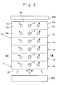
- the body 11 has an upper face 11a, a lower face 11b, opposite side faces 11c and 11d, and opposite end faces 11e and 11f.
- the body 11 has six regions or portions V1 to V6 corresponding respectively to the six actuators A1 to A6.
- the regions V1 to V6 are arranged in this order from the end face 11e to the end face 11f along the length of the body 11.
- Each of the regions V1 to V6 has two actuator ports A and B which are connected to a respective one of the actuators A1 to A6 via two pipes (not shown).
- each pair of actuator ports A and B are connected respectively to two oil chambers of a respective one of these hydraulic cylinders.
- a directional control valve 100, a pressure compensation valve 200 and a shuttle valve 300 are incorporated in each of the five regions V2 to V6 of the body 11.
- the directional control valve 100 serves to control the direction of flow of the oil to a corresponding one of the actuators A1 to A6 and to control the flow rate of the oil.
- the pressure compensation valve 200 serves to compensate for the amount of the oil flowing through the directional control valve 100.
- the shuttle valves 300 serve to select the greatest (maximum) load pressure among the load pressures acting respectively on the actuators A1 to A6.
- a similar directional control valve 100 and a similar pressure compensation valve 200 are incorporated in the region V1 disposed immediately adjacent to the end face 11e of the body 11.
- each of the regions V1 to V6 of the body 11 has the two actuator ports A and B extending vertically and opening to the upper face 11a; a transverse hole 20 horizontally extending straight through the body 11 and opening at its opposite ends to the opposite side faces 11c and 11d of the body 11; and a vertical hole 30 vertically extending straight through the body 11 and opening at its opposite ends to the upper and lower faces 11a and 11b of the body 11.
- the vertical hole 30 perpendicularly intersects a central portion of the transverse hole 20, and a load pressure chamber 40 for receiving load pressure (later described) is provided at this intersection.
- the vertical hole 30 has an upper portion 30a disposed above the load pressure chamber 40, and a lower portion 30b disposed below the load pressure chamber 40.
- the transverse hole 20 is arranged generally symmetrically with respect to the center of the load pressure chamber 40, and left and right portions 20a and 20b of the transverse hole 20 communicate with the upper portion 30a of the vertical hole 30 via respective passages 50 and 50.
- the pair of actuator ports A and B, the transverse hole 20, the vertical hole 30, the load pressure chamber 40 and the two passages 50 and 50 are disposed substantially on a plane disposed perpendicular to the direction of arrangement of the regions V1 to V6.
- Each of the left and right portions 20a and 20b of the transverse hole 20 has three annular grooves 21, 22 and 23 arranged in this order from the load pressure chamber 40.
- Each of the passages 50 and 50 communicates at its lower end with the corresponding inner annular groove 21.
- the actuator port A communicates at its lower end with the intermediate annular groove 22 of the left portion 20a, and similarly the actuator port B communicates at its lower end with the intermediate annular groove 22 of the right portion 20b.
- the outer annular grooves 23 communicate with tank ports Xt, respectively, as later described.
- each of the left and right portions 20a and 20b has a first guide portion 24 disposed between the load pressure chamber 40 and the annular groove 21, a second guide portion 25 disposed between the annular grooves 21 and 22, and a third guide portion 26 disposed between the annular grooves 22 and 23.
- Each of the left and right portions 20a and 20b of the transverse hole 20 has a narrow annular grooves 25a disposed immediately adjacent to one end of the guide groove 25 close to the load pressure chamber 40.
- An abutment wall 31 is formed on the inner peripheral surface of the vertical hole 30 and disposed above the load pressure chamber 40, and a port 31a constituting part of the vertical hole 30 is formed through the abutment wall 31.
- the upper portion 30a of the vertical hole 30 communicates at its lower end with the load pressure chamber 40 via the port 31a.
- the upper portion 30a of the vertical hole 30 has three annular grooves 32, 33 and 34 arranged in this order from above.
- the pair of passages 50 and 50 communicate at their upper ends with the upper annular groove 32.
- the intermediate annular groove 33 communicates with a pump port Xp as later described.
- the lower annular groove 34 communicates with a pilot pump port Xpi as later described.
- the annular grooves 33 and 34 are disposed between the pair of passages 50 and 50.
- the inner peripheral surface of the upper portion 30a of the vertical groove 30 are divided by the three annular grooves 32 to 34 into four guide portions 35 to 38 arranged in this order from above.
- the inner diameter d1 of the lowermost guide portion 38 is smaller than the inner diameter d2 of the other three guide portions 35 to 37.
- a narrow annular groove 36a is formed in the upper end of the guide portion 36.
- the inner diameter of the upper end section of the upper portion 30a of the vertical hole 30 is greater than the inner diameter of the guide portion 35, and internal threads 39a are formed on the inner periphery of this upper end section.
- the inner diameter of the lower end section of the lower portion 30b of the vertical hole 30 is greater than the inner diameter than the remainder of the lower portion 30b, and internal threads 39b are formed on the inner peripheral surface of this lower end section.
- the annular grooves 33 of the upper portions 30a of the vertical holes 30 of each adjacent ones of the regions V1 to V6 communicate with each other via a passage 61.
- the annular groove 33 of the region V6 disposed immediately adjacent to the end face 11f of the body 11 communicates via a passage 61 with the pump port Xp formed in the end face 11f of the body 11. With this arrangement, the annular grooves 33 of the six regions V1 to V6 all communicate with the pump port Xp.
- the annular grooves 34 of each adjacent ones of the regions V1 to V6 communicate with each other via a passage 62.
- the annular groove 34 of the region V6 disposed immediately adjacent to the end face 11f of the body 11 communicates via a passage 62 with the pilot pump port Xpi formed in the end face 11f of the body 11. With this arrangement, the annular grooves 34 of the six regions V1 to V6 all communicate with the pilot pump port Xpi.
- the lower portions 30b of the vertical holes 30 of each adjacent ones of the regions V1 to V6 communicate with each other via a passage 63.
- the lower portion 30b of the region V6 disposed immediately adjacent to the end face 11f of the body 11 communicates via a passage 63 with a detection pressure port D formed in the end face 11f of the body 11.
- annular grooves 23 of the left portions 20a of the transverse holes 20 of each adjacent ones of the regions V1 to V6 communicate with each other via a passage 64.
- the annular grooves 23 of the right portions 20b of the transverse holes 20 of each adjacent ones of the regions V1 to V6 communicate with each other via a passage 65.
- the annular grooves 23 of the region V6 disposed immediately adjacent to the end face 11f of the body 11 respectively communicate via respective passages 64 and 65 with the pair of tank ports Xt formed in the end face 11f of the body 11.
- the six passages 61, the six passages 62, the six passages 63, the six passages 64 and the six passages 65 extend along five straight lines, respectively.
- the load pressure chambers 40 of the regions V1 to V6 are disposed independently of one another.
- the directional control valve 100 is received in the transverse hole 20, and the pressure compensation valve 200 is received in the upper portion 30a of the vertical hole 30.
- the shuttle valve 300 is received in the lower portion 30b of the vertical hole 30.
- the directional control valve 100 includes a spool 110 which is slidably received in the transverse hole 20 for movement therealong.
- the spool 110 has at its central portion a land portion 111 received in the load pressure chamber 40.
- Each of the left and right portions of the spool 110 has two land portions 112 and 113 arranged in this order from the land portion 111 toward the end of the spool 110.
- the two land portions 112 of the left and right portions of the spool 110 cooperate respectively with the guide portions 25 of the left and right portions 20a and 20b of the transverse hole 20 to allow and interrupt the communication between the actuator port A and the corresponding passage 50 and the communication between the actuator B and the corresponding passage 50.
- the two land portions 113 of the left and right portions of the spool 110 cooperate respectively with the guide portions 26 of the left and right portions 20a and 20b of the transverse hole 20 to allow and interrupt the communication between the actuator port A and the corresponding tank port Xt and the communication between the actuator B and the corresponding tank port Xt.
- Each of the left and right portions of the spool 110 has an annular recess 114 disposed between the lands 112 and 113, and one end of the land portion 112 disposed immediately adjacent to the recess 114 is tapered as at 112a toward the recess 114. This tapered portion 112a cooperates with the annular groove 25a of the transverse hole 20 to constitute a throttle portion 115.
- a notch 113a is formed in one end of the land 113 disposed immediately adjacent to the recess 114.
- Each of the left and right portions of the spool 110 has a passage 120.
- the passage 120 serves to communicate the load pressure chamber 40 with the actuator port A or the actuator port B when the spool 110 is operated, as will hereinafter be more fully described.
- Each passage 120 comprises an axial bore 121 extending axially from the end of the spool 110, and small-diameter holes 122 formed through the peripheral wall of the spool 110 and disposed between the land portions 111 and 112, and a stepped hole 123 of a small diameter formed radially through the land portion 113.
- the opposite ends of the spool 110 are projected outwardly from the opposite side faces 11c and 11d of the body 11, respectively.
- Plugs 130 and 140 are threaded respectively into the ends of the axial holes 121 of the spool 110 at the opposite ends of the spool 110.
- An operating lever (not shown) is connected to the left end of the spool 110 through the plug 130.
- a centering spring mechanism 150 is connected to the right end of the spool 110 through the plug 140.
- the centering spring mechanism 150 is a known device which holds the spool 110 in its neutral position (shown in Fig. 3) when the above operating lever is in its inoperative condition.
- the centering spring mechanism 150 comprises a washer 151 engaged with the right end of the spool 110 in the neutral position of the spool 110, a washer 152 engaged with a flange 140a of the plug 140 in the neutral position of the spool 110, and a compression spring 153 acting between the two washers 151 and 152.
- the centering spring mechanism 150 is covered by a cover member 155 fixedly mounted on the side face 11d of the body 11.
- the spool 110 When the above operating lever is in its inoperative condition, the spool 110 is maintained in its neutral position shown in Fig. 3. In this condition, the land portions 112 and 113 of the left portion of the spool 110 are respectively held in contact with the guide portions 25 and 26 over the entire peripheries thereof. Therefore, the left actuator port A is not communicated with the mating passage 50 and the mating tank port Xt. Similarly, the right actuator port B is not communicated with the mating passage 50 and the mating tank portion Xt.
- the load pressure chamber 40 is in communication with the tank ports Xt and Xt via the passages 120 and 120, and therefore the pressure in the load pressure chamber 40 is substantially equal to the atmospheric pressure.
- the land portion 113 of the left portion of the spool 110 is still kept in contact with the guide portion 26 of the transverse hole 20 over the entire periphery thereof, but the land portion 112 of the left portion of the spool 110 is disengaged from the guide portion 25 to open the throttle portion 115. Therefore, the actuator port A is caused to communicate with the passage 50, but the communication of the actuation port A with the tank port Xt remains interrupted. As a result, the oil under high pressure is fed from the pressure compensation valve 200 via the passage 50, the throttle 115 and the actuator port A to the corresponding actuator.
- the actuator port B is caused to communicate with the tank port Xt, but the communication of the actuation port B with the passage 50 remains interrupted.
- the oil is fed from the corresponding actuator to a tank T (later described) via the actuator port B and the tank port Xt.
- the actuator is driven in one direction.
- the small-diameter hole 123 of the left passage 120 is communicated with the actuator port A but is not communicated with the tank port Xt, so that the load pressure chamber 40 is caused to communicate with the actuator port A via the passage 120.
- the small-diameter ports 122 of the right passage 120 are closed by the guide portion 24, so that the communication between the load pressure chamber 40 and the right tank port Xt is interrupted. Therefore, the load pressure appearing at the actuator port A can be introduced into the load pressure chamber 40.
- the load pressure chamber 40 communicates with the actuator port B via the right passage 120, and is not communicated with the two tank ports Xt. Therefore, the load pressure appearing at the actuator port B can be introduced into the load pressure chamber 40.
- the degree of opening of the throttle portion 115 constitutes an important factor for determining the amount of supply of oil to the actuator.
- the pressure compensation valve 200 includes a balance piston 210.
- the balance piston 210 comprises an upper member 210A and a lower member 210B connected to the upper member 210A, the balance piston 210 being slidably received in the upper portion 30a of the vertical hole 30.
- the lower member 210B has five land portions 211 to 215 arranged in this order from above.
- the diameter of the land portions 211 to 214 is substantially equal to the diameter d2 of the guide portions 35, 36 and 37 of the vertical hole 30 formed in the body 11.
- the diameter of the land portion 215 is substantially equal to the diameter d1 of the guide portion 38 of the vertical hole 30.
- the land portions 211 to 215 are always kept in contact with their mating guide holes 35 to 38 of the vertical hole 30.
- a notch 212a is formed in the lower end of the land portion 212, and the notch 212a cooperates with the annular groove 36a, formed in the guide portion 36, to constitute a throttle portion 216.
- An annular recess 220 formed in the outer periphery of the lower member 210B and disposed between the land portions 211 and 212 communicates with the two passages 50 and 50 in the body 11.
- the guide portion 36 faces an annular recess 221 which is formed in the outer periphery of the lower member 210B and is disposed between the land portions 212 and 213.
- An annular recess 222 formed in the outer periphery of the lower member 210B and disposed between the land portions 213 and 214, is disposed in the annular groove 33 communicating with the pump port Xp.
- a recess 225 is formed in the lower end face of the lower member 210B of the balance piston 210, and a vibration-absorbing spring 226 is received in the recess 225.
- the lower member 210B of the balance piston 210 has an axial hole 230 extending axially downward from the upper end face of the lower member 210B.
- the axial hole 230 has a lower reduced-diameter portion and an upper greater-diameter portion, and a step 231 is formed between these two portions.
- the step 231 serves as a valve seat as later described.
- a load check valve 400 Received within the axial hole 230 of the lower member 210B is a load check valve 400 which comprises a valve body 410.
- the valve body 410 has a slide portion 411 disposed in sliding contact with the greater diameter portion of the axial hole 230, and a head 412 at its lower end.
- the valve body 410 is urged downward by a relatively weak spring 420 to hold the valve head 412 in sealing contact with the valve seat 231.
- the axial hole 230 is divided or partitioned by the slide portion 411 of the valve body 410 into two sections.
- Holes 232 are formed through the peripheral wall of the lower member 210B of the balance piston 210, and are disposed below the valve seat 231.
- the axial hole 230 communicates with the pump port Xp via the through holes 232, the annular recess 222 and the annular groove 33 of the body 11.
- Holes 233 are formed through the peripheral wall of the lower member 210B, and are disposed above and adjacent to the valve seat 231.
- the axial hole 230 communicates with the annular recess 221 via the through holes 233.
- a hole 234 of a small diameter is also formed through the peripheral wall of the lower member 210B, and is disposed above the slide portion 411.
- the axial hole 230 communicates with the two passages 50 and 50 via the hole 234 and the annular recess 220.
- the lower end portion of the upper member 210A of the balance piston 210 is threaded into the upper portion of the axial hole 230 of the lower member 210B.
- the upper member 210A has a peripheral flange 240 intermediate the opposite ends thereof, and the lower surface of the flange 240 abuts against the upper end of the lower member 210B.
- the upper member 210A has a land portion 241 disposed above the flange 240, the land portion 241 having a diameter d3.
- the relation of the diameter d3 with respect to the above-mentioned diameters d1 and d2 is as follows: d3 ⁇ d1 ⁇ d2
- the upper member 210A also has an axial hole 243 axially extending upwardly from the lower end face thereof, and holes 244 of a small diameter extending transversely from the upper end of the axial hole 243 to the outer peripheral surface of the upper member 210A, the holes 243 being disposed between the land portion 241 and the flange 240.
- a cap assembly 250 is mounted in the upper end section of the vertical hole 30 of the body 11.
- the cap assembly 250 comprises a tubular adapter 251 threaded at its lower portion into the upper end section of the vertical hole 30, a cap-shaped bushing 252 received in the adapter 251, and a pipe fitting 253 threaded at its lower portion into the upper portion of the adapter 251 and held at its lower end face against a projection 252a formed on the upper end of the bushing 252.
- the land portion 241 of the upper member 210A of the balance piston 210 is slidably received in the bushing 252.
- the pipe fitting 253 is has an axial hole C into which a pipe (not shown) is fitted.
- the axial hole C serves as a control pressure port for introducing a control pressure as later described.
- the pipe fitting 253 also has a hole 253a extending downward from the lower end of the control pressure port C to the lower end face of the pipe fitting 253.
- a hole 252b is formed through the upper wall of the bushing 252.
- the pressure compensation valve 200 has four important pressure introduction chambers Ypc, Yps, Ypi and Ypa arranged in this order from above.
- the uppermost or first pressure introduction chamber Ypc is formed between the upper wall of the bushing 252 and the land portion 241 of the balance piston 210.
- a control pressure Pc is fed from the control pressure port C to the pressure introduction chamber Ypc via the hole 253a of the pipe fitting 253, a space formed between the lower end face of the pipe fitting 253 and the upper end face of the bushing 252 and the hole 252b of the bushing 252.
- the second pressure introduction chamber Yps is formed by the upper end section of the vertical hole 30 of the body 11 which is closed by the cap assembly 250.
- a supply pressure Ps supplied from the pressure compensation valve 200 to the directional control valve 100 (that is, the pressure in the passages 50) is introduced into the pressure introduction chamber Yps via the hole 234, a space between the upper member 210A of the balance piston 210 and the valve member 410 of the load check valve 400, the axial hole 243 and the holes 244.
- the third pressure introduction chamber Ypi is formed by the annular groove 34 and the outer peripheral surface of the balance piston 210.
- a pilot pump pressure Pi is fed from the pilot pump port Xpi to the pressure introduction chamber Ypi.
- the fourth or lowermost pressure introduction chamber Ypa is formed by the recess 225 of the balance piston 210 and the abutment wall 31.
- a load pressure Pa from the load pressure chamber 40 is introduced into the pressure introduction chamber Ypa via the through hole 31a.
- the balance piston 210 When the balance piston 210 is in its lowermost position as shown in Fig. 4, the land portion 212 is disposed in contact with the guide portion 36 of the vertical hole 30 over the entire periphery thereof to close the throttle portion 216. Therefore, in this condition, the passages 50 are not in communication with the pump port Xp.
- the throttle portion 216 When the balance piston 210 moves upward a predetermined amount, the throttle portion 216 is opened. The degree of opening of the throttle portion 216 increases as the balance piston 210 further moves upward.
- the spring 226 is designed to absorb vibrations, and the force exerted by the spring 226 on the balance piston 210 is so small that it can be disregarded.
- the pump pressure P is applied from the pump port Xp to the land portions 213 and 214 via the annular groove 33 of the body 11, the forces acting respectively on the land portions 213 and 214 cancel each other since the pressure receiving areas of these two land portions 213 and 214 are equal to each other.
- the pump pressure P also urges the valve body 410 of the load check valve 400 upward, and is applied to the land portions 212 and 213 via the holes 233 and the annular recess 221.
- the forces acting respectively on the land portions 212 and 213 cancel each other since the pressure receiving areas of these two land portions 212 and 213 are equal to each other. Therefore, the forces exerted by the pump pressure P directly on the balance piston 210 are disregarded.
- the effective pressure receiving area Spa of the balance piston 210 at the pressure introduction chamber Ypa is determined by the diameter d1 of the land portion 215 of the balance piston 210.
- the effective pressure receiving area Spi of the balance piston 210 at the pressure introduction chamber Ypi is determined by the difference between the diameter d2 of the land portion 214 and the diameter d1 of the land portion 215.
- the effective pressure receiving area Sps of the balance piston 210 at the pressure introduction chamber Yps is determined by the difference between the diameter d2 of the land portion 211 and the diameter d3 of the land portion 241.
- the position of the balance piston 210 (and hence the degree of opening of the throttle portion 216 of the pressure compensation valve 200) is determined in such a manner that the opening force Fo and the closing force Fd are equal to each other.
- the operation of the pressure compensation valve 200 will now be described from the viewpoint of its pressure compensation function.
- the operation of the pressure compensation valve 200 will now be described more specifically.
- the degree of opening of the throttle portion 115 corresponding to the actuator port A or the actuator port B increases in accordance with the movement of the spool 110 of the directional control valve 100
- the balance piston 210 is moved upward so as to increase the degree of opening of the throttle portion 216.
- the flow rate (flow amount per unit time) of the throttle portion 115 is increased so that the above pressure difference (Ps - Pa) can be kept at K (Pi - Pc), thereby increasing the amount of supply of the oil to the corresponding actuator.
- the degree of opening of the throttle portion 115 of the directional control valve 100 is decreased, the degree of opening of the throttle portion 216 of the pressure compensation valve 200 is decreased, thereby decreasing the amount of supply of the oil to the corresponding actuator.
- the amount of supply of the oil to the actuator and hence the speed of driving of the actuator can be controlled.
- the degree of opening of the throttle portion 216 increases so as to increase the supply pressure Ps, thereby maintaining the difference between the two pressures Ps and Pa at K (Pi - Pc).
- the degree of opening of the throttle portion 216 is decreased so as to decrease the supply pressure Ps.
- the shuttle valve 300 includes a holder 310 received oil-tight in the lower portion 30b of the vertical hole 30.
- the holder 310 has a peripheral flange 311 eccentric from the the axis of the holder 310.
- the flange 311 is received in a counterbore 30x provided at the lower portion 30b of the vertical hole 30, the counterbore 30x being eccentric from the axis of the vertical hole 30.
- the holder 310 is received in position in the lower portion 30b of the vertical hole 30.
- a plug 320 is threaded into the threaded portion 39b provided at the lower end of the lower portion 30b. The plug 320 urges the flange 311 of the holder 310 against a stepped portion 30y formed on the inner peripheral surface of the vertical hole 30, thereby holding the holder 310 against movement.
- the holder 310 has an axial stepped hole 312 extending downward from its upper end face.
- a tapered shoulder or step 313 formed on the inner peripheral surface of the axial hole 312 serves as a first valve seat.
- a valve seat member 330 is threaded into the upper end portion of the axial hole 312, the valve seat member 330 having an axial hole 331 (first inlet port) formed therethrough.
- a tapered lower surface 332 of the valve seat member 330 serves as a second valve seat. That portion of the axial hole 312 disposed between the second valve seat 332 and the first valve seat 313 serves as a valve chamber 340.
- a valve member 350 in the form of a ball is received within the valve chamber 340.
- the valve chamber 340 communicates with the load pressure chamber 40 via the axial hole 331 of the valve seat member 330.
- the valve chamber 340 is also connected to the left-hand passage 63 (Fig. 5) via a transverse hole 315 (which is formed in the holder 310 and extends between the lower end of the axial hole 312 and the outer peripheral surface of the holder 310) and an axial groove 316 formed in the outer peripheral surface of the holder 310.
- the transverse hole 315 and the axial groove 316 jointly provide a second inlet port.
- the valve chamber 340 is also connected to the right-hand passage 63 via a transverse hole 317, formed in the holder 310, and an axial groove 318 formed in the outer peripheral surface of the holder 310.
- the transverse hole 317 and the vertical groove 318 jointly provide an outlet port.
- the shuttle valves 300 are incorporated or contained respectively in the five regions V2 to V6 of the body 11.
- the other region V1 disposed adjacent to the end face 11e of the body 11 does not need the shuttle valve 300, and therefore the lower end of the vertical hole 30 of the region V1 is closed by a closure member instead of the shuttle valve 300.
- the vertical hole 30 may not open to the lower face 11b of the body 11.
- the shuttle valve 300 may be mounted in the lower portion 30b of the vertical hole 30 as described above for the other five regions V2 to V6, in which case the shuttle valve 300 at the region V1 does not make a comparison between two pressures as described later but merely passes the pressure of the load pressure chamber 40 to the right-hand passage 63.
- the oil pressure fed to this shuttle valve 300 via the left-hand passage 63 from the adjacent shuttle valve 300 disposed on the left side thereof is compared with the load pressure Pa of the load pressure chamber 40 to which the shuttle valve 300 is exposed.
- the valve member 350 moves upward into contact with the second valve seat 332, so that the valve chamber 340 is communicated with the passage 63 and that the communication of the valve chamber 340 with the load pressure chamber 40 is interrupted.
- the pressure of the left-hand passage 63 is fed to the right-hand passage 63 via the valve chamber 340.
- the valve member 350 moves downward into contact with the first valve seat 313, so that the valve chamber 340 is communicated with the load pressure chamber 40 and that the communication of the valve chamber 340 with the left-hand passage 63 is interrupted. As a result, the load pressure Pa is fed to the right-hand passage 63 via the valve chamber 340.
- the maximum or greatest load pressure PI among the load pressures Pa introduced respectively into the six regions V1 to V6 is outputted from the detection pressure port D connected to the shuttle valve 300 of the final stage (that is, the shuttle valve 300 disposed adjacent to the end face 11f of the body 11).
- the unload and relief valve device 600 includes a body 610 in the form of a unitary block.
- the body 610 has opposite parallel side faces 610a and 610b which are substantially flat, and opposite end faces 610c and 610d.
- the body 610 is mounted in stacked relation to the body 11, with the side face 610a abutted against the end face 11f of the body 11.
- the body 610 has an axial hole 611, and one end of the axial hole 611 is closed while the other end of the axial hole 611 is open to the end face 610c of the body 610.
- a plug 620 is threaded into the open end of the axial hole 611.
- Annular grooves 612 and 613 are formed in the inner peripheral surface of the axial hole 611, and are disposed respectively adjacent to the opposite ends of the axial hole 611.
- the annular grooves 612 and 613 communicate respectively with the tank ports Xt of the body 11 via respective passages 614 and 615 formed in the body 610.
- the annular grooves 612 and 613 also communicate with a single tank port (not shown) formed in the upper surface of the body 610 which is substantially parallel to the sheet of Fig. 8. This tank port is connected to a tank T (Fig. 9) via a pipe.
- the inner peripheral surface of the axial hole 611 has guide portions 616 and 617 which are disposed on the opposite sides of and immediately adjacent to the the annular groove 613.
- a tubular guide member 630 is fixedly fitted in the axial hole 611, and is disposed on the right side (Fig. 8) of and immediately adjacent to the annular groove 612.
- the unload valve 610A comprises a spool 640 which has three land portions 641, 642 and 643 arranged in this order from the left (Fig. 8).
- the left-hand land portion 641 is always held in contact with the right-hand end portion of the inner peripheral surface of the guide member 630.
- the right-hand land portion 643 is always held in contact with the guide portion 617.
- the intermediate land portion 642 is brought into and out of contact with the guide portion 616, depending on the position of the spool 640.
- a pump pressure chamber 650 is defined by the inner peripheral surface of the axial hole 611, the outer peripheral surface of the spool 640, the guide portion 616 and the guide member 630.
- the pump pressure chamber 650 is connected to the pump ports Xp of the body 11 via a passage 618 formed in the body 610.
- the pump pressure chamber 650 also communicates with a pump port (not shown) formed in the upper surface of the body 610. This pump port in the body 610 is connected to the main pump P (Fig. 9) via a pipe.
- a pilot chamber 660 is formed between the right end face of the spool 640 and the right end wall of the body 610.
- the pilot chamber 660 communicates with the pump pressure chamber 650 via an axial hole 645 (which is formed in the right end portion of the spool 640) and a hole 646 of a small diameter extending between the axial hole 645 and the outer peripheral surface of the spool 640. Therefore, the pump pressure of the main pump P is introduced into the pilot chamber 660.
- a pressure introduction chamber 670 is defined by the axial hole 647, the inner peripheral surface of the guide member 630 and the right end of the plug 620.
- a spring 671 is received within the pressure introduction chamber 670, and urges the spool 640 in a right-hand direction.
- the pressure introduction chamber 670 is connected to the detection pressure port D of the body 11 via an orifice 631 formed through the peripheral wall of the guide member 630, an annular groove 632 in the outer peripheral surface of the guide member 630 and a passage 619 formed in the body 610. Therefore, the aforesaid maximum load pressure PI detected by the shuttle valve 300 is introduced into the pressure introduction chamber 670.
- An axial hole 621 is formed in the plug 620 and is open to the left end face of the plug 620.
- a relief valve 600B is received within the axial hole 621. More specifically, a set screw 622 is threaded into the left end portion of the axial hole 621.
- the axial hole 621 communicates with the annular groove 612 via holes 625 of a small diameter formed through the peripheral wall of the plug 620.
- the axial hole 621 also communicates with the pressure introduction chamber 670 via a valve port 681 formed through the right-hand end wall of the plug 620.
- the valve port 681 is opened and closed by a valve member 680 received within the axial hole 621.
- a spring 683 is also received within the axial hole 621, and urges the valve member 680 toward the valve port 681 to close the same.
- the annular groove 632 in the outer periphery of the guide member 630 is connected to a detection pressure port (not shown) formed in the upper surface of the body 610, and this detection pressure port in the body 610 is connected via a pipe to one of input ports of a pressure differential detector 810 later described.
- the body 610 has a passage connected at one end to the pilot pump port Xpi of the body 11, and the other end of this passage is connected via a pipe to a pilot pump Pi later described.
- the ports Xp, Xpi, Xt and D of the body 11 are connected respectively to the main pump P, the pilot pump port Pi, the tank T and the pressure differential detector 810 via the respective passage means (formed in the body 610) and pipes.
- the land portion 642 is brought into contact with the guide portion 616 to close the unload valve 600A. At this time, the difference between the pump pressure P and the maximum load pressure PI becomes less than ⁇ P.
- the hydraulic system further comprises the following devices.
- a relief valve 700 is connected to the outlet side of the pilot pump Pi, and the pilot pump pressure Pi fed from the pilot pump Pi is maintained at a constant level.
- Electromagnetic proportional pressure control valves 800 corresponding in number to the actuators A1 to A6 are connected via pipes respectively to the control pressure ports C of the regions V1 to V6 of the hydraulic control apparatus 10.
- the hydraulic control system further comprises pressure differential detector 810, and a controller 805 which is responsive to a detection signal from the pressure differential detector 810 to control the electromagnetic proportional pressure control valves 800.
- the pressure differential detector 810 detects the difference between the pump pressure P and the maximum load pressure PI.
- the controller 805 controls the electromagnetic proportional pressure control valves 800 in accordance with the thus detected pressure differential (P - PI), so that the valves 800 respectively output the control pressure Pc, represented by the following formula, to the control pressure ports C of the regions V1 to V6:
- Pc Pi - (P - PI) (6)
- each pressure compensation valve 200 controls so that the difference between the supply pressure Ps and the load pressure Pa is proportional to the difference between the pump pressure P and the maximum load pressure PI.
- the amount of supply of the oil to the actuator per unit time is maintained at a level corresponding to the degree of opening of the throttle portion 115 of the directional control valve 100.
- the speed of driving of the actuator is kept at a level corresponding to the amount of the operation of the spool 110.
- the pressure differences (Ps - Pa) in all of the pressure compensation valves 200 becomes less than K ⁇ P, and as a result the amounts of supply of the oil to all of the actuators in their driving condition per unit time decrease, so that the speeds of driving of the actuators are decreased at the same rate.
- the total amount of the oil required by the actuators in their driving condition is limited, thereby ensuring that all of the pressure compensation valves 200 can continue to properly perform their functions. As a result, not only the actuators under low load but also the actuators under high load can properly operate in a well balanced manner.
- the pump pressure P controlled by the unload valve 600A ceases to vary in response to the maximum load pressure PI and is kept at the maximum pump pressure Pmax.
- the controller 805 has means by which the outputs of the electromagnetic proportional pressure control valves 800 can be manually set at respective individual values. With this arrangement, when necessary, the value of the control pressure Pc, outputted from a selected one of these valves 800, is set at zero, so that the throttle portion 216 of the corresponding pressure compensation valve 200 is fully opened, thereby releasing the function of this pressure compensation valve 200.
- the load pressure chamber 40 is provided at the intersection between the vertical hole 30 and the transverse hole 20, and the pressure compensation valve 200 and the shuttle valve 300 are mounted respectively in the upper and lower portions 30a and 30b of the vertical hole 30. Both of the pressure compensation valve 200 and the shuttle valve 300 are exposed to the load pressure chamber 40.
- the transverse hole 20, the vertical hole 30 and the pair of passages 50 and 50 in each of the regions V1 to V6 of the body 11 is disposed substantially on the plane disposed perpendicular to the direction of arrangement of the regions V1 to V6 of the body 11.
- the directional control valve 100, the pressure compensation valve 200 and the shuttle valve 300 at any one of the regions V1 to V6 are disposed on the above plane. With this arrangement, the hydraulic control apparatus 10 can be very compact in construction.
- the main pump pressure P may be introduced into each pressure introduction chamber 900 to which the step 223 of the balance piston 210 is exposed, and the maximum load pressure PI may be introduced directly into the corresponding port C via a pipe.
- the pressure compensation valve 200 operates so that the above formula (7) can be established.
- Those parts of Fig. 10 corresponding to those of Fig. 4 are designated by identical reference numerals, respectively, and will not be described further here.
- the embodiment of Fig. 10 obviates the need for the electromagnetic proportional control valves 800 and the controller 805 of the preceding embodiment.
- each port C may be omitted in the embodiment of Fig. 10, in which case the maximum load pressure PI is introduced into the pressure introduction chamber Ypc via a passage formed in the body 11.
- the pressure (P - PI) from the electromagnetic proportional pressure control valve 800 may be introduced into the pressure introduction chamber Ypi, in which case the pressure introduction chamber Ypc is omitted or is communicated with the atmosphere.
- the hydraulic control system includes two actuators, only one shuttle valve may be used.
- body 610 of the unload and relief valve device 600 may be integral with the body 11.
- the regions V1 to V6 of the body 10 may be formed respectively by separate blocks, in which case these separate blocks are connected together in stacked relation to one another.
- check valves may be used as detection valves instead of the shuttle valves. Since each check valve is similar in construction to each shuttle valve 300 shown in Fig. 5, the check valves are not shown here, and instead will now be described with reference to Fig. 5. Instead of the axial grooves 313 and 318, a groove is formed in the outer peripheral surface of each holder 310 either over the entire periphery or about a half of the periphery of the holder 310, holes 317 and 315 communicating with this groove. Each adjacent passages 63 and 63 are connected together via this groove. The check valves are received respectively in the lower portions 30b of all the regions V1 to V6 corresponding respectively to the actuators.
- a valve member 350 of the check valve which receives the maximum load pressure from the load pressure chamber 40 is engaged with a first valve seat 313, and the maximum load pressure is applied to all of the other check valves via the passages 63. Therefore, in each of the other check valves, the valve member 350 is moved into contact with a second valve seat 332 to interrupt the communication between the load pressure chamber 40 and a valve chamber 340. Thus, the maximum load pressure is outputted from the detection port D (Fig. 6).
- One of the passages 63 is connected to the tank via a passage (formed in the body 11 and having an orifice) so as to relief the pressures in all of the passages 63, so that the check valves can respond to the maximum load pressure.
Landscapes
- Engineering & Computer Science (AREA)
- General Engineering & Computer Science (AREA)
- Mechanical Engineering (AREA)
- Physics & Mathematics (AREA)
- Fluid Mechanics (AREA)
- Mining & Mineral Resources (AREA)
- Civil Engineering (AREA)
- Structural Engineering (AREA)
- Fluid-Pressure Circuits (AREA)
- Operation Control Of Excavators (AREA)
Claims (13)
- Système de commande hydraulique pour l'entraînement d'une pluralité d'actionneurs (A1 à A6), comprenant :(a) une pompe (P);(b) une pluralité de soupapes de commande directionnelles (100) correspondant respectivement à la pluralité d'actionneurs (A1 à A6), chaque soupape de commande directionnelle comprenant un couple de parties d'étranglement aval (115) disposées entre ladite pompe (P) et l'actionneur correspondant, et un tiroir (110) pour commander le degré d'ouverture dudit couple de parties d'étranglement aval (115), et l'une ou l'autre desdites deux parties d'étranglement aval étant ouverte en fonction du déplacement dudit tiroir (110) pour appliquer le fluide à l'actionneur correspondant à partir de ladite pompe (P);(c) des moyens formant soupape de détection (300,810) comprenant au moins une soupape de détection (300) servant à détecter la pression de charge maximale (PI) parmi les pressions de charge de la pluralité d'actionneurs (A1 à A6); et(d) une pluralité de soupapes de compensation de pression (200) correspondant respectivement à la pluralité d'actionneurs, chaque soupape de compensation de pression comprenant une partie d'étranglement amont (216) disposée entre ladite pompe (P) et ledit couple de parties d'étranglement aval (115), et un piston d'équilibrage (210) pour commander le degré d'ouverture de ladite partie d'étranglement amont (216), ledit piston d'équilibrage (210) comportant une première partie de réception de pression (215), qui reçoit la pression de charge (Pa) de l'actionneur correspondant de manière à déplacer ledit piston d'équilibrage dans le sens de l'ouverture de ladite partie d'étranglement amont (216), ledit piston d'équilibrage (210) possédant également une seconde partie de réception de pression (240), qui reçoit une pression d'alimentation (Ps) délivrée par ladite partie d'étranglement amont (216) auxdites parties d'étranglement aval (115) de manière à déplacer ledit piston d'équilibrage (210) dans le sens de fermeture de ladite partie d'étranglement amont (216), ledit piston d'équilibrage comprenant des moyens de réception de pression (223,241) servant à recevoir pour l'essentiel une pression de fonctionnement (Pi, Pc), qui diminue lorsque la différence entre la pression (P) de ladite pompe et la pression de charge maximum (PI) détectée par lesdits moyens formant soupape de détection (300,810) diminue de telle sorte que ledit piston d'équilibrage (210) peut être déplacé dans le sens de l'ouverture de ladite partie d'étranglement amont (216), et la position dudit piston d'équilibrage (210) étant commandée de telle sorte que la force agissant sur ledit piston d'équilibrage sous l'effet de la différence entre ladite pression d'alimentation (Ps) et ladite pression de charge (Pa) peut être en équilibre avec la force agissant sur ledit piston d'équilibrage sous l'effet de ladite pression d'actionnement (Pi,Pc) reçue par lesdits moyens de réception de pression (223,241) ;caractérisé en ce qu'il est prévu des moyens formant corps (11) comprenant une pluralité de régions (V1 à V6) correspondant respectivement à la pluralité d'actionneurs (A1 à A6), ladite pluralité de soupapes de commande directionnelles (100) ainsi que ladite pluralité de soupapes de compensation de pression (200) étant montées respectivement dans ladite pluralité de régions (V1 à V6), chacune desdites régions comprenant un premier trou rectiligne (20) et un second trou rectiligne (30), qui recoupent sensiblement perpendiculairement une partie centrale dudit premier trou, ledit tiroir (110) étant logé avec possibilité de glissement dans ledit premier trou (20) de la région correspondante desdits moyens formant corps (11), l'intersection entre lesdits premier et second trous (20,30) formant une chambre de pression de charge (40) servant à recevoir la pression de charge (Pa) de l'actionneur correspondant, et ledit second trou (30) possédant une première partie (30a) et une seconde partie (30b) entre lesquelles est intercalée ladite chambre de pression de charge (40), ledit piston d'équilibrage (210) de ladite soupape de compensation de pression (200) étant logé, avec possibilité de glissement, dans ladite première partie (30a) dudit second trou (30) de la région correspondante desdits moyens formant corps (11) ladite première partie de réception de pression (215) dudit piston d'équilibrage (210) étant dirigée vers ladite chambre de pression de charge, et ladite soupape de détection (300) étant logée dans ladite seconde partie (30b) dudit second trou (30) de l'une desdites régions (V1 à V6) desdits moyens formant corps (11) de manière à recevoir la pression de charge (Pa) de la part de ladite chambre de pression de charge (40).
- Système de commande hydraulique selon la revendication 1, dans lequel ladite pluralité de régions (V1 à V6) desdits moyens formant corps (11) sont juxtaposées, ledit premier trou (20) et ledit second trou (30) de chaque région de ladite pluralité de régions (V1 à V6) étant disposés dans un plan perpendiculaire à la direction d'agencement de ladite pluralité de régions.
- Système de commande hydraulique selon la revendication 2, dans lequel lesdits moyens formant corps (11) comprennent un bloc unitaire, dans lequel ladite pluralité de régions (V1 à V6) sont disposées continûment les unes à la suite des autres.
- Système de commande hydraulique selon la revendication 3, dans lequel chaque région de ladite pluralité de régions (V1 à V6) comporte un couple d'orifices (A,B) pour un actionneur, situés dans ledit plan, les premières extrémités desdits deux orifices de l'actionneur débouchant dans une surface extérieure dudit bloc et étant raccordées à l'actionneur correspondant (A1 à A6), tandis que les autres extrémités sont raccordées à des parties latérales opposées (20a, 20b) dudit premier trou (20) situées respectivement sur les côtés opposés de ladite chambre de pression de charge (40), chaque région de ladite pluralité de régions possédant un couple de premiers passages (50) situés dans ledit plan, et l'extrémité de chacun desdits premiers passages étant raccordée à ladite première partie (30a) dudit second trou (30), située entre des extrémités opposées de ladite première partie, tandis que l'autre extrémité est raccordée à la partie dudit premier trou (20) située entre ladite chambre de pression de charge et l'autre extrémité dudit orifice de l'actionneur.
- Système de commande hydraulique selon la revendication 4, dans lequel ledit tiroir (110) de ladite soupape de commande directionnelle (100) comporte un couple de seconds passages (120); en fonction du déplacement dudit tiroir dans un sens, ladite chambre de pression de charge (40) étant amenée à communiquer par l'intermédiaire de l'un desdits seconds passages (120) avec un orifice (A) dudit couple d'orifices de l'actionneur, dans lequel circule le fluide provenant de ladite pompe (P); et conformément au déplacement du tiroir dans le sens opposé, ladite chambre de pression de charge étant amenée à communiquer, par l'intermédiaire de l'autre second passage (120), avec l'autre orifice (B) de l'actionneur, dans lequel circule le fluide provenant de ladite pompe.
- Système de commande hydraulique selon la revendication 5, dans lequel lesdits moyens formant corps (11) comportent un passage d'alimentation en fluide (33,61) qui s'étend selon un trajet rectiligne dans la direction d'agencement de ladite pluralité de régions et qui recoupe sensiblement perpendiculairement lesdites premières parties (30a) desdits seconds trous (30) de ladite pluralité de régions (V1 à V6) entre des extrémités opposées de chaque première partie, une extrémité dudit passage d'alimentation en fluide débouchant dans la surface extérieure desdits moyens formant corps de manière à former un orifice (Xp) raccordé à ladite pompe (P), ledit piston d'équilibrage (210) possédant une première portée (212) engagée, avec possibilité de glissement, avec la partie de la surface périphérique intérieure dudit second trou (30) disposée entre l'intersection dudit passage d'alimentation en fluide (33,61) et dudit second trou et l'intersection de chacun dudit premier passage (50) et dudit second trou, ladite portée coopérant avec ladite partie de manière à former ladite partie d'étranglement amont (216), ledit tiroir (110) possédant un couple de secondes portées (113) engagées avec possibilité de glissement contre la périphérie intérieure dudit premier trou (20), une portée dudit couple de secondes portées coopérant avec la partie de la surface périphérique intérieure dudit premier trou, située entre l'intersection de l'un desdits deux orifices (A,B) de l'actionneur et ledit premier trou et l'intersection de l'un desdits deux premiers passages (50) et dudit premier trou pour former l'une desdites deux parties d'étranglement aval (115), et la seconde portée coopérant avec la partie de la surface périphérique à l'intérieur dudit premier trou, située entre l'intersection de l'autre orifice de l'actionneur et ledit premier trou et l'intersection de l'autre premier passage et ledit premier trou pour former l'autre partie d'étranglement aval.
- Système de commande hydraulique selon la revendication 2, dans lequel lesdits moyens de réception de la pression dudit piston d'équilibrage (210) comprennent une troisième partie de réception de pression (233), qui reçoit une première pression de commande, et une quatrième partie de réception de pression (241), qui sert à recevoir une seconde pression de commande, la force agissant sur ledit piston d'équilibrage sous l'effet de ladite première pression de commande servant à déplacer ledit piston d'équilibrage dans le sens de l'ouverture de ladite partie d'étranglement amont (216), la force agissant sur ledit piston d'équilibrage sous l'effet de ladite seconde pression de commande étant utilisée pour déplacer ledit piston d'équilibrage dans le sens de la fermeture de ladite partie d'étranglement amont, et une différence entre ladite première pression de commande et ladite seconde pression de commande définissant ladite pression de fonctionnement reçue par lesdits moyens de réception de pression, et étant sensiblement égale à la différence entre ladite pression de la pompe et ladite pression de charge maximale.
- Système de commande hydraulique selon la revendication 7, dans lequel ladite quatrième partie de réception de pression (241) est formée sur une extrémité dudit piston d'équilibrage (210), qui est distante de ladite chambre de pression de charge (40), lesdites seconde et troisième parties de réception de pression (240, 223) étant formées sur la partie dudit piston d'équilibrage qui est située entre les extrémités opposées de ce piston.
- Système de commande hydraulique selon la revendication 7, comprenant, en outre, un détecteur de pression différentielle (810) servant à détecter une différence entre ladite pression de la pompe et ladite pression de charge maximale pour délivrer un signal de détection, des moyens (Pi,700) pour produire ladite première pression de commande, et des moyens (800,805) pour produire ladite seconde pression de commande, lesdits moyens de production de la première pression de commande comprenant une pompe pilote (Pi) pour appliquer ladite première pression de commande à un niveau constant à ladite troisième partie de réception de pression (223) dudit piston d'équilibrage (210), lesdits moyens produisant la seconde pression de commande étant aptes à répondre audit signal de détection pour envoyer ladite seconde pression de commande à ladite quatrième partie de réception de pression (241), et ladite seconde pression de commande étant sensiblement égale à une valeur obtenue en soustrayant de ladite première pression de commande la différence de pression détectée par ledit détecteur de pression différentielle.
- Système de commande hydraulique selon la revendication 9, dans lequel lesdits moyens formant corps (11) comprennent, en outre, un passage (34,62) de transmission de la pression pilote, qui s'étend selon une disposition rectiligne dans la direction d'agencement de ladite pluralité de régions (V1 à V6) et est raccordé auxdites premières parties (30a) desdits seconds trous (30) de ladite pluralité de régions entre les extrémités opposées de ladite première partie (30a), une extrémité dudit passage de transmission débouchant dans la surface extérieure desdits moyens formant corps de manière à former un orifice (Xpi) de la pompe pilote, ladite troisième partie (223) de réception de la pression, que comporte ledit piston d'équilibrage (210), étant exposée à la partie dudit second trou (20), dans laquelle ledit passage de transmission (34,62) est raccordé audit second trou.
- Système de commande hydraulique selon la revendication 7, dans lequel ladite pression de la pompe est appliquée en tant que première pression de commande directement à ladite troisième partie de réception de pression (223), la pression de charge maximale délivrée par lesdits moyens formant soupape de détection (300) étant appliquée en tant que seconde pression de commande à ladite quatrième partie de réception de pression (241).
- Système de commande hydraulique selon la revendication 2, dans lequel lesdits moyens de réception de pression comportent une troisième partie de réception de pression (223) servant à recevoir une pression sensiblement égale à une différence entre ladite pression de la pompe et ladite pression de charge maximale de manière à déplacer ledit piston d'équilibrage (210) dans le sens de l'ouverture de ladite partie d'étranglement amont (216).
- Système de commande hydraulique selon la revendication 3, dans lequel lesdits moyens formant soupape de détection comprennent une pluralité desdites soupapes de détection chacune sous la forme d'une soupape à alternance (300), ledites soupapes à alternance étant logées respectivement dans lesdites secondes parties (30b) desdits seconds trous (30) de l'ensemble desdites régions desdits moyens formant corps, hormis pour une région (V1) disposée dans une position directement adjacente à une extrémité desdits moyens formant corps, chaque soupape à alternance comprenant un premier orifice d'entrée (331) exposé à ladite chambre de pression de charge (40), un second orifice d'entrée (315,316), un orifice de sortie (317,318), ledit orifice de sortie de chacune des soupapes à alternance adjacente étant raccordé audit second orifice d'entrée de l'autre soupape à alternance par l'intermédiaire d'un passage de transmission de pression (63), ladite chambre de pression de charge de ladite première région (V1) desdits moyens formant corps étant raccordée audit second orifice d'entrée de ladite soupape à alternance de la région (V2), qui lui est adjacente, desdits moyens formant corps par l'intermédiaire d'un passage de transmission de pression (63), ledit orifice de sortie de ladite soupape à alternance de ladite région (V6) situé en position directement adjacente à l'autre extrémité desdits éléments formant corps, qui est distante de ladite première région (V1), étant raccordé par l'intermédiaire d'un passage de transmission de pression (63) à un orifice à pression de détection (D) formé dans la surface extérieure desdits moyens formant corps, de sorte que la pression de charge maximale est délivrée par ledit orifice à pression de détection, et l'ensemble desdits passages de transmission de pression étant disposé le long d'une ligne droite qui s'étend dans la direction d'agencement de ladite pluralité de régions.
Applications Claiming Priority (2)
| Application Number | Priority Date | Filing Date | Title |
|---|---|---|---|
| JP63284593A JPH0786361B2 (ja) | 1988-11-10 | 1988-11-10 | 油圧制御弁 |
| JP284593/88 | 1988-11-10 |
Publications (3)
| Publication Number | Publication Date |
|---|---|
| EP0368636A2 EP0368636A2 (fr) | 1990-05-16 |
| EP0368636A3 EP0368636A3 (fr) | 1991-05-02 |
| EP0368636B1 true EP0368636B1 (fr) | 1993-06-09 |
Family
ID=17680465
Family Applications (1)
| Application Number | Title | Priority Date | Filing Date |
|---|---|---|---|
| EP89311554A Expired - Lifetime EP0368636B1 (fr) | 1988-11-10 | 1989-11-08 | Système de commande hydraulique |
Country Status (5)
| Country | Link |
|---|---|
| US (1) | US5025625A (fr) |
| EP (1) | EP0368636B1 (fr) |
| JP (1) | JPH0786361B2 (fr) |
| KR (1) | KR920005765B1 (fr) |
| DE (1) | DE68907020T2 (fr) |
Families Citing this family (41)
| Publication number | Priority date | Publication date | Assignee | Title |
|---|---|---|---|---|
| JPH07103882B2 (ja) * | 1989-03-22 | 1995-11-08 | 株式会社小松製作所 | 圧力補償付液圧弁 |
| DE69022985T2 (de) * | 1989-10-11 | 1996-03-21 | Hitachi Construction Machinery Co., Ltd., Tokio/Tokyo | Hydraulische antriebsanordnung fuer hochbau/oder bauausruestung. |
| EP0477370B2 (fr) * | 1990-01-11 | 1998-11-04 | Hitachi Construction Machinery Co., Ltd. | Valve hydraulique |
| DE4005967C2 (de) * | 1990-02-26 | 1996-05-09 | Rexroth Mannesmann Gmbh | Steueranordnung für mehrere hydraulische Verbraucher |
| JPH0758082B2 (ja) * | 1990-06-22 | 1995-06-21 | 株式会社ゼクセル | 油圧制御弁装置 |
| JPH0768962B2 (ja) * | 1990-06-22 | 1995-07-26 | 株式会社ゼクセル | ロードセンシング機能付き方向切換弁 |
| JPH07109205B2 (ja) * | 1990-06-22 | 1995-11-22 | 株式会社ゼクセル | 油圧制御弁 |
| JPH0473403A (ja) * | 1990-07-11 | 1992-03-09 | Nabco Ltd | 油圧回路 |
| JP3018117B2 (ja) * | 1990-08-10 | 2000-03-13 | 株式会社▲高▼梨油気圧 | 流量調整機能付切換弁装置 |
| JPH087452Y2 (ja) * | 1990-11-30 | 1996-03-04 | 株式会社ゼクセル | 油圧制御弁におけるスプールの回動防止機構 |
| FR2672944A1 (fr) * | 1991-02-15 | 1992-08-21 | Bennes Marrel | Distributeur proportionnel et ensemble de commande d'une pluralite de recepteurs hydrauliques comportant pour chaque recepteur un tel distributeur. |
| JP2575156Y2 (ja) * | 1991-11-12 | 1998-06-25 | 株式会社小松製作所 | 圧油供給装置 |
| FR2689575B1 (fr) * | 1992-04-06 | 1994-07-08 | Rexroth Sigma | Distributeur hydraulique a compensation de pression et une selection de pression maximale pour piloter une pompe et commande hydraulique multiple incluant de tels distributeurs. |
| KR0145143B1 (ko) * | 1992-10-29 | 1998-08-01 | 오까다 하지메 | 유압제어밸브장치 및 유압구동장치 |
| JP2869311B2 (ja) * | 1993-09-30 | 1999-03-10 | 新キャタピラー三菱株式会社 | 油圧アクチュエータ用のバルブ制御装置 |
| US5715865A (en) * | 1996-11-13 | 1998-02-10 | Husco International, Inc. | Pressure compensating hydraulic control valve system |
| US5791142A (en) * | 1997-03-27 | 1998-08-11 | Husco International, Inc. | Hydraulic control valve system with split pressure compensator |
| US5878647A (en) * | 1997-08-11 | 1999-03-09 | Husco International Inc. | Pilot solenoid control valve and hydraulic control system using same |
| US5890362A (en) * | 1997-10-23 | 1999-04-06 | Husco International, Inc. | Hydraulic control valve system with non-shuttle pressure compensator |
| US5950429A (en) * | 1997-12-17 | 1999-09-14 | Husco International, Inc. | Hydraulic control valve system with load sensing priority |
| FR2787148B1 (fr) * | 1998-12-09 | 2001-02-16 | Mannesmann Rexroth Sa | Distributeur hydraulique |
| DE19904616A1 (de) | 1999-02-05 | 2000-08-10 | Mannesmann Rexroth Ag | Steueranordnung für wenigstens zwei hydraulische Verbraucher und Druckdifferenzventil dafür |
| US6526747B2 (en) * | 2000-01-25 | 2003-03-04 | Hitachi Construction Machinery Co., Ltd. | Hydraulic driving device |
| US6745564B2 (en) * | 2001-12-21 | 2004-06-08 | Volvo Construction Equipment Holding Sweden Ab | Hydraulic variable control apparatus for heavy construction equipment |
| US6695231B2 (en) | 2002-02-15 | 2004-02-24 | Dramm Corporation | Irrigation system for growing plants at a growing facility |
| DE10325296A1 (de) * | 2003-06-04 | 2004-12-23 | Bosch Rexroth Ag | Hydraulische Steueranordnung |
| JP4276491B2 (ja) * | 2003-08-04 | 2009-06-10 | 日立建機株式会社 | 方向切換弁ブロック |
| JP4012495B2 (ja) * | 2003-09-09 | 2007-11-21 | 日立建機株式会社 | 油圧駆動装置 |
| DK1860327T3 (da) * | 2006-05-26 | 2010-04-19 | Hydrocontrol S P A | Trykkompenserende retningsbestemt styreventil |
| US20140175773A1 (en) * | 2012-12-20 | 2014-06-26 | Caterpillar Inc. | Flow rectifier assembly |
| US10508964B2 (en) | 2013-03-14 | 2019-12-17 | Eaton Intelligent Power Limited | Solenoid valve assembly with pilot pressure control |
| US9523438B2 (en) * | 2013-03-14 | 2016-12-20 | Eaton Corporation | Solenoid valve assembly with pilot pressure control |
| KR20160040581A (ko) * | 2013-08-13 | 2016-04-14 | 볼보 컨스트럭션 이큅먼트 에이비 | 건설기계용 유량 제어밸브 |
| EP3347531B8 (fr) * | 2015-09-18 | 2021-04-28 | Rost Innovation LLC | Système de compensation de soupape de commande |
| US10989232B2 (en) | 2015-09-18 | 2021-04-27 | Rost Innovation LLC | Control valve compensation system |
| US20180149175A1 (en) * | 2016-11-30 | 2018-05-31 | Schlumberger Technology Corporation | Metering Fluid to a Fluid Actuator |
| US10458439B2 (en) * | 2016-11-30 | 2019-10-29 | Schlumberger Technology Corporation | Metering fluid to fluid actuators |
| US11376666B2 (en) * | 2017-10-27 | 2022-07-05 | Tri Tool Inc. | Pipe facing machine system |
| JP7139297B2 (ja) * | 2019-09-25 | 2022-09-20 | 日立建機株式会社 | 流量制御弁 |
| US12442396B2 (en) * | 2020-01-27 | 2025-10-14 | Parker-Hannifin Corporation | Valve with an adjustable flow sharing pressure compensator |
| JP7439036B2 (ja) * | 2021-11-01 | 2024-02-27 | 株式会社竹内製作所 | 作業用車両の作動制御装置 |
Citations (1)
| Publication number | Priority date | Publication date | Assignee | Title |
|---|---|---|---|---|
| JPS6011706A (ja) * | 1983-06-14 | 1985-01-22 | リンデ・アクチエンゲゼルシヤフト | 1つのポンプとこのポンプによつて負荷される少なくとも2つの液力作業装置とを有する液力式装置 |
Family Cites Families (15)
| Publication number | Priority date | Publication date | Assignee | Title |
|---|---|---|---|---|
| US3970108A (en) * | 1973-10-23 | 1976-07-20 | Cross Manufacturing, Inc. | Priority hydraulic control valve |
| DE2701509C2 (de) * | 1977-01-15 | 1985-10-31 | Robert Bosch Gmbh, 7000 Stuttgart | Hydraulische Steuereinrichtung für wenigstens zwei hydraulische Verbraucher |
| US4154262A (en) * | 1977-10-17 | 1979-05-15 | Gresen Manufacturing Company | Hydraulic control system |
| JPS57110884A (en) * | 1980-12-27 | 1982-07-09 | Nippon Air Brake Co Ltd | Direction changeover valve equipped with pressure compensation valve |
| DE3422165A1 (de) * | 1983-06-14 | 1984-12-20 | Linde Ag, 6200 Wiesbaden | Hydraulische einrichtung mit einer pumpe und mindestens zwei von dieser beaufschlagten verbrauchern hydraulischer energie |
| DE3428403A1 (de) * | 1983-08-01 | 1985-04-11 | Závody těžkého strojírenství Výzkumný ústav stavebních a zemních stroju, Brünn/Brno | Zweistufige, druckkompensierte hydraulische steuereinrichtung fuer mindestens zwei verbraucher |
| JPS6110707A (ja) * | 1984-06-26 | 1986-01-18 | Norito Suzuki | 光ビ−ト測長装置 |
| DE3507121A1 (de) * | 1985-02-28 | 1986-08-28 | Mannesmann Rexroth GmbH, 8770 Lohr | Mehrwegeventil mit druckwaage |
| DE3532816A1 (de) * | 1985-09-13 | 1987-03-26 | Rexroth Mannesmann Gmbh | Steueranordnung fuer mindestens zwei von mindestens einer pumpe gespeiste hydraulische verbraucher |
| DE3644737C2 (de) * | 1985-09-13 | 1995-11-23 | Rexroth Mannesmann Gmbh | Steueranordnung für mindestens zwei von mindestens einer Pumpe gespeiste hydraulische Verbraucher |
| US4709724A (en) * | 1986-01-17 | 1987-12-01 | Commercial Shearing, Inc. | Fluid valve structures |
| IT1187892B (it) * | 1986-02-04 | 1987-12-23 | Chs Vickers Spa | Circuito idraulico di comando per organi di lavoro di macchine movimento terra con frenatura centralizzata degli attuatori |
| DE3644745A1 (de) * | 1986-12-30 | 1988-07-14 | Rexroth Mannesmann Gmbh | Steueranordnung fuer mindestens zwei von mindestens einer pumpe gespeiste hydraulische verbraucher |
| IN171213B (fr) * | 1988-01-27 | 1992-08-15 | Hitachi Construction Machinery | |
| JPH0755361Y2 (ja) * | 1988-02-29 | 1995-12-20 | 株式会社ナブコ | 圧力補償弁を有する方向切換弁 |
-
1988
- 1988-11-10 JP JP63284593A patent/JPH0786361B2/ja not_active Expired - Fee Related
-
1989
- 1989-11-07 US US07/432,858 patent/US5025625A/en not_active Expired - Fee Related
- 1989-11-08 DE DE89311554T patent/DE68907020T2/de not_active Expired - Fee Related
- 1989-11-08 EP EP89311554A patent/EP0368636B1/fr not_active Expired - Lifetime
- 1989-11-10 KR KR1019890016285A patent/KR920005765B1/ko not_active Expired
Patent Citations (1)
| Publication number | Priority date | Publication date | Assignee | Title |
|---|---|---|---|---|
| JPS6011706A (ja) * | 1983-06-14 | 1985-01-22 | リンデ・アクチエンゲゼルシヤフト | 1つのポンプとこのポンプによつて負荷される少なくとも2つの液力作業装置とを有する液力式装置 |
Also Published As
| Publication number | Publication date |
|---|---|
| KR920005765B1 (ko) | 1992-07-18 |
| JPH02134402A (ja) | 1990-05-23 |
| EP0368636A2 (fr) | 1990-05-16 |
| DE68907020D1 (de) | 1993-07-15 |
| KR900008205A (ko) | 1990-06-02 |
| EP0368636A3 (fr) | 1991-05-02 |
| US5025625A (en) | 1991-06-25 |
| DE68907020T2 (de) | 1993-10-28 |
| JPH0786361B2 (ja) | 1995-09-20 |
Similar Documents
| Publication | Publication Date | Title |
|---|---|---|
| EP0368636B1 (fr) | Système de commande hydraulique | |
| KR960000577B1 (ko) | 벨브장치 | |
| EP0900962B1 (fr) | Electrovanne pilote et système hydraulique utilisant la même | |
| US5533334A (en) | Pressurized fluid supply system | |
| US6073652A (en) | Pilot solenoid control valve with integral pressure sensing transducer | |
| JP2618396B2 (ja) | 油圧制御システム | |
| EP3752683B1 (fr) | Soupape de commande hydraulique conçue pour utiliser un signal pilote en tant que signal de détection de charge de substitution | |
| JPWO1993005301A1 (ja) | 弁装置 | |
| JPH0758082B2 (ja) | 油圧制御弁装置 | |
| JP2557000B2 (ja) | 操作弁装置 | |
| GB2383383A (en) | Check valve control | |
| GB2294558A (en) | Capacity control device for variable capacity hydraulic pump | |
| JPH06123301A (ja) | 建設機械の油圧制御装置 | |
| US6089248A (en) | Load sense pressure controller | |
| US5735311A (en) | Pressure compensation valve | |
| EP0080135A1 (fr) | Système de commande hydraulique pour un opérateur hydraulique | |
| JPH07109205B2 (ja) | 油圧制御弁 | |
| JPH01312201A (ja) | 油圧流量制御装置 | |
| JP3454313B2 (ja) | 圧油供給装置 | |
| CA1146444A (fr) | Systeme de commande a compensation de pression et de debit neutralisee par detecteurs de compte et de viscosite | |
| JPH05332311A (ja) | 圧油供給装置 | |
| JPH05332315A (ja) | 圧油供給装置 | |
| JPH02134403A (ja) | 方向制御弁 | |
| JPH05332310A (ja) | 圧油供給装置 | |
| KR960004185Y1 (ko) | 굴삭기 유압회로의 가변 오리피스장치 |
Legal Events
| Date | Code | Title | Description |
|---|---|---|---|
| PUAI | Public reference made under article 153(3) epc to a published international application that has entered the european phase |
Free format text: ORIGINAL CODE: 0009012 |
|
| AK | Designated contracting states |
Kind code of ref document: A2 Designated state(s): DE FR IT |
|
| PUAL | Search report despatched |
Free format text: ORIGINAL CODE: 0009013 |
|
| AK | Designated contracting states |
Kind code of ref document: A3 Designated state(s): DE FR IT |
|
| 17P | Request for examination filed |
Effective date: 19910613 |
|
| 17Q | First examination report despatched |
Effective date: 19920914 |
|
| GRAA | (expected) grant |
Free format text: ORIGINAL CODE: 0009210 |
|
| AK | Designated contracting states |
Kind code of ref document: B1 Designated state(s): DE FR IT |
|
| REF | Corresponds to: |
Ref document number: 68907020 Country of ref document: DE Date of ref document: 19930715 |
|
| ET | Fr: translation filed | ||
| ITF | It: translation for a ep patent filed | ||
| PLBE | No opposition filed within time limit |
Free format text: ORIGINAL CODE: 0009261 |
|
| STAA | Information on the status of an ep patent application or granted ep patent |
Free format text: STATUS: NO OPPOSITION FILED WITHIN TIME LIMIT |
|
| 26N | No opposition filed | ||
| PGFP | Annual fee paid to national office [announced via postgrant information from national office to epo] |
Ref country code: FR Payment date: 19981110 Year of fee payment: 10 |
|
| PGFP | Annual fee paid to national office [announced via postgrant information from national office to epo] |
Ref country code: DE Payment date: 19981116 Year of fee payment: 10 |
|
| PG25 | Lapsed in a contracting state [announced via postgrant information from national office to epo] |
Ref country code: FR Free format text: LAPSE BECAUSE OF NON-PAYMENT OF DUE FEES Effective date: 20000731 |
|
| PG25 | Lapsed in a contracting state [announced via postgrant information from national office to epo] |
Ref country code: DE Free format text: LAPSE BECAUSE OF NON-PAYMENT OF DUE FEES Effective date: 20000901 |
|
| REG | Reference to a national code |
Ref country code: FR Ref legal event code: ST |
|
| PG25 | Lapsed in a contracting state [announced via postgrant information from national office to epo] |
Ref country code: IT Free format text: LAPSE BECAUSE OF NON-PAYMENT OF DUE FEES Effective date: 20051108 |