EP0368700A1 - Vorrichtung zum axialen Sperren eines teleskopischen Teiles, z.B. einer Kraftfahrzeuglenksäule - Google Patents
Vorrichtung zum axialen Sperren eines teleskopischen Teiles, z.B. einer Kraftfahrzeuglenksäule Download PDFInfo
- Publication number
- EP0368700A1 EP0368700A1 EP89402818A EP89402818A EP0368700A1 EP 0368700 A1 EP0368700 A1 EP 0368700A1 EP 89402818 A EP89402818 A EP 89402818A EP 89402818 A EP89402818 A EP 89402818A EP 0368700 A1 EP0368700 A1 EP 0368700A1
- Authority
- EP
- European Patent Office
- Prior art keywords
- collar
- link
- control lever
- articulation
- collars
- Prior art date
- Legal status (The legal status is an assumption and is not a legal conclusion. Google has not performed a legal analysis and makes no representation as to the accuracy of the status listed.)
- Withdrawn
Links
- 230000000717 retained effect Effects 0.000 claims description 3
- 238000006073 displacement reaction Methods 0.000 abstract description 3
- 230000000295 complement effect Effects 0.000 abstract description 2
- 230000000903 blocking effect Effects 0.000 description 7
- 210000000078 claw Anatomy 0.000 description 1
Images


Classifications
-
- B—PERFORMING OPERATIONS; TRANSPORTING
- B62—LAND VEHICLES FOR TRAVELLING OTHERWISE THAN ON RAILS
- B62D—MOTOR VEHICLES; TRAILERS
- B62D1/00—Steering controls, i.e. means for initiating a change of direction of the vehicle
- B62D1/02—Steering controls, i.e. means for initiating a change of direction of the vehicle vehicle-mounted
- B62D1/16—Steering columns
- B62D1/18—Steering columns yieldable or adjustable, e.g. tiltable
- B62D1/184—Mechanisms for locking columns at selected positions
Definitions
- the present invention relates to the axial locking of a telescopic member, the internal and external elements of which must both be able to be displaced axially with respect to one another and be driven in a rigorously integral manner during their use.
- telescopic members of this type must be associated with an axial locking device making it possible, on the one hand, to rigorously lock one against the other the internal and external elements and, on the other hand, to release easily when you want to make an adjustment. This is particularly the case of steering columns with adjustment by relative axial displacement of some of their elements, which must be able to be easily modified by the driver of the vehicle, then locked in a very safe and almost instantaneous manner.
- the present invention aims to provide an axial locking device which is particularly safe and effective while requiring only a relatively low and clearly determined force.
- the subject of this invention is in fact a device for axially locking a telescopic member, such as a motor vehicle steering column, comprising an external element which is deformable until it adheres with an internal element, which comprises two half-collars which are hinged together at one end, a connecting rod articulated on a first half-collar and supported on a flat side directed tangentially outward from the second half-collar, and a control lever which passes through lights opposite the flat side and the link and is articulated on each of them so that in the position of maximum clamping of the half-collars and deformation of the external element the three axes of articulation are in the same plane.
- the two half-collars extend beyond their articulation and carry between their extension tension adjustment means.
- the locking and unlocking positions thus correspond to well determined positions of the control lever and of the link, while the passage from one to the other requires only a reasonable effort which can in fact be provided by n any motor vehicle driver.
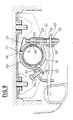
- the locking device according to the invention is intended to be mounted on a telescopic member which comprises, as shown in particular in Fig.1, at least one internal element 1 which is inserted in an external element 2 capable of being deformed so to adhere to the right of the blocking device to the external surface of the internal element 1.
- the internal and external elements 1 and 2 are tubes of circular section and the external tube 2 has at least one longitudinal slot 4, but it will be clear that the internal and external elements may have different shapes and that the deformation of the external element 2 can be obtained by other means.
- the blocking device comprises two half-collars 6 and 8 respectively which constitute, in the exemplary embodiment shown, an upper half-collar 6 and a lower half-collar 8.
- the upper half-collar 6 comprises (Fig. 6) a curved surface 10 substantially forming a half-cylinder and extended at each of its ends by a substantially flat sidewall, 11, 12 respectively, one of these sidewalls, 11, being itself extended by a narrower tab curved towards the 'outside 14.
- the lower half-collar 8 also has an arcuate surface 16 which is extended at one of its ends by a flat sidewall 18, but the latter is directed towards the outside of the surface 16 and of the collar.
- the bearing surface 16 is pierced with a slot 20 which is crossed by the tab 14 of the upper collar 6 and in which the latter can pivot (FIG. 1).
- This end is also extended by a flat part 22 curved outwards to form a second side 24 parallel to the side 18.
- a screw 26 is screwed into a tapped hole 28 of the flat part 22 and constitutes an adjustable stop against which comes to bear. paw 14.
- the link 30 in fact comprises, in the vicinity of one of its ends, a lug 32 which is in pivoting support in the rounded and narrowed end 34 of a cutout 36 of the upper collar 6, and at its end opposite or lower end, a guide and retaining lug 40 which is curved at 42 around the lower edge of the sidewall 18.
- This rod 30 is further retained externally by a bent finger 38 in one piece with the upper half-collar .
- the link 30 and the sidewall 18 comprise furthermore each a profiled lumen, respectively 44, 46, forming a ball joint articulation element 45, 47 which cooperates with a complementary element formed on a control lever 48.
- the articulation elements 45 and 47 are bosses projecting inside the corresponding lumen 44, 46, which are directed in opposite directions, and the control lever 48 is an elongated element comprising two opposite longitudinal grooves 49 and 50.
- the operating lever 48 is extended by a control rod 52 which passes through a guide orifice 54 of the sidewall 24 and is terminated by an operating handle 56 (Fig.7).
- the control lever 48 can thus easily be tilted and pivot around the articulation 47 which connects it to the lower half-collar, which causes the rod 30 to pivot in one direction or the other, that is to say - say towards a blocking position or towards an unlocking position.
- a pivoting of the control lever 48 around the boss 47 pushes the boss 45 and the link 30 laterally, to the right considering Fig.3, and rotates the lug 32 in the cutout 34.
- the distance between the axis of lug 32 and that of the articulation 45, 50 remains the same but the articulation 47, 49 leaves the plane of the two other articulations and thus moves away from the lug 32, which allows the sides 18 and 12 to move apart the one from the other and as a result of the half-collars 6 and 8 loosen their grip on the external element 2.
- the adhesion between the internal elements 1 and external 2 is eliminated so that they can be moved axially relative to each other.
- a simple pivoting in the opposite direction of the control lever 48 is sufficient to ensure a new effective and safe locking when the desired position has been reached.
- the lumen 46 of the sidewall 18 preferably has substantially the shape of a sector so that its lateral edges constitute stops which ensure the limits of the pivoting stroke of the control lever 48 and of the link rod 30 while the cooperation of the screw 26 and of the lug 14 ensures precise adjustment of the tightening tension.
- the lower half-collar 8 comprises axial tabs 58, projecting inside the concavity of its bearing surface 16, which fit together in the notches of the external element (2) and cooperate with longitudinal openings made opposite one another in the wall of the internal element 1.
- the tabs 58 play the role of guide members during the relative axial displacement of these two elements but above all immobilize the latter in rotation with respect to each other and with respect to half-collars and secure the lower half-collar with the outer tube.
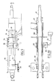
- the blocking device comprises, as before, an upper half-collar 60 and a lower half-collar 8 which are hinged together at one end by means of a lug 14, an extension of the upper half-collar, which passes through a lumen 20 of the other half-collar and abuts when the device is tightened against an adjustment screw 26.
- a link 62 is pivotally mounted on the two half-collars thanks to a lug 64 free to rotate in an orifice 66 in the upper collar 60.
- This link is applied against the outer faces of the planar sides 12 and 18 of the two half-collars by means of a spring leaf 68 which is folded at its upper part to form an arm 70 terminated by a hook 72 introduced into an oblong slot 74 formed in the half-collar 60 substantially at its upper part.
- the spring 68 is also pierced with a hole 76 allowing the free passage of the control lever 48.
- the lever carries, on the one hand, a claw washer 78 in contact with the spring 68, and on the other hand, a stop 79 in contact with the sidewall 18 which cooperate to limit the radial clearance between the link 62 and the sidewall 18 of the lower half-collar.
- the unlocking or blocking movement is therefore carried out in a safe and simple manner with the aid of a reasonable but clearly determined effort.
- the locking device according to the invention is thus particularly suitable for use when the telescopic member is a steering column of a motor vehicle, the steering shaft of which consists of two tubes 80 and 81 which are axially movable relative to one another and one of which is axially integral with a column body 82 while the other is axially integral with an envelope tube 84.
- the envelope tube 84 surrounds the column body 82 and carries a locking device for the steering column 86.
- the tube 84 which constitutes an external element of the telescopic system is split longitudinally at 88 along two diametrically opposed generatrices, so that it can be deformed by the locking device 86 until it is completely adhered to the periphery of the body of column 82.
- the assembly of the steering column 90 is fixed in the body 92 of the vehicle by means of fittings 94, 95, on the one hand at 96 above the steering column 90, and on the other hand at 98 below the latter.
- the fitting 94 further comprises two tabs 100 which each penetrate into one of the slots 88 of the envelope tube 84 and thus ensures with its slots guidance of the axial movement of the envelope tube.
- the small size of the locking device 86 allows it to be completely inside the volume occupied by the support fittings 94, 95, although the operating handle 56 is close enough to the steering wheel to be easily accessible by the driver.
- this operating handle is moved in a plane parallel to the axis of the column to cause the control lever 48 to pivot, which is particularly practical for the user and requires only a reduced space.
Landscapes
- Engineering & Computer Science (AREA)
- Chemical & Material Sciences (AREA)
- Combustion & Propulsion (AREA)
- Transportation (AREA)
- Mechanical Engineering (AREA)
- Steering Controls (AREA)
Applications Claiming Priority (2)
| Application Number | Priority Date | Filing Date | Title |
|---|---|---|---|
| FR8813486 | 1988-10-13 | ||
| FR8813486A FR2637949B1 (fr) | 1988-10-13 | 1988-10-13 | Dispositif de blocage axial d'un organe telescopique tel qu'une colonne de direction de vehicule automobile |
Publications (1)
| Publication Number | Publication Date |
|---|---|
| EP0368700A1 true EP0368700A1 (de) | 1990-05-16 |
Family
ID=9370987
Family Applications (1)
| Application Number | Title | Priority Date | Filing Date |
|---|---|---|---|
| EP89402818A Withdrawn EP0368700A1 (de) | 1988-10-13 | 1989-10-12 | Vorrichtung zum axialen Sperren eines teleskopischen Teiles, z.B. einer Kraftfahrzeuglenksäule |
Country Status (2)
| Country | Link |
|---|---|
| EP (1) | EP0368700A1 (de) |
| FR (1) | FR2637949B1 (de) |
Cited By (9)
| Publication number | Priority date | Publication date | Assignee | Title |
|---|---|---|---|---|
| EP0499508A1 (de) * | 1991-02-15 | 1992-08-19 | Nacam | Lenksäulen-Anordnung für ein Kraftfahrzeug |
| WO1996036520A1 (en) * | 1995-05-18 | 1996-11-21 | Nastech Europe Limited | Steering column clamping mechanism |
| EP0881137A2 (de) | 1997-05-27 | 1998-12-02 | NEW HOLLAND ITALIA S.p.A. | Klemmvorrichtung |
| FR2783790A1 (fr) * | 1998-09-24 | 2000-03-31 | Ecia Equip Composants Ind Auto | Ensemble de colonne de direction reglable en position notamment pour vehicule automobile |
| FR2822782A1 (fr) * | 2001-04-03 | 2002-10-04 | Nacam | Dispositif de serrage d'une colonne de direction de vehicule automobile |
| FR2876074A1 (fr) * | 2004-10-01 | 2006-04-07 | Traven Technology Sa | Dispositif de reglage de colonne de direction |
| US7686336B2 (en) | 2005-09-01 | 2010-03-30 | Trw Lucasvarity Electric Steering Limited | Steering column assembly |
| US9085320B2 (en) | 2005-09-01 | 2015-07-21 | Trw Limited | Steering column assembly |
| CN111042906A (zh) * | 2019-11-29 | 2020-04-21 | 全椒赛德利机械有限公司 | 一种高密封性的汽车发动机散热器 |
Citations (5)
| Publication number | Priority date | Publication date | Assignee | Title |
|---|---|---|---|---|
| US2144140A (en) * | 1938-01-24 | 1939-01-17 | Standard Mfg Co | Clamping device |
| FR2465111A1 (fr) * | 1979-09-06 | 1981-03-20 | Itw De France | Collier de serrage auto-verrouillable |
| EP0098898A1 (de) * | 1982-07-12 | 1984-01-25 | Hoshino Gakki Company, Ltd. | Vorrichtung zur gegenseitigen Fixierung von Stangen in ausgewählten Stellungen |
| EP0202959A1 (de) * | 1985-03-25 | 1986-11-26 | Nacam | Verriegelungseinrichtung einer Kraftfahrzeuglenksäule mit Kniestück-Sperrmitteln |
| US4639979A (en) * | 1984-05-30 | 1987-02-03 | Strength, Tech, Inc. | Barbell collar |
-
1988
- 1988-10-13 FR FR8813486A patent/FR2637949B1/fr not_active Expired - Lifetime
-
1989
- 1989-10-12 EP EP89402818A patent/EP0368700A1/de not_active Withdrawn
Patent Citations (5)
| Publication number | Priority date | Publication date | Assignee | Title |
|---|---|---|---|---|
| US2144140A (en) * | 1938-01-24 | 1939-01-17 | Standard Mfg Co | Clamping device |
| FR2465111A1 (fr) * | 1979-09-06 | 1981-03-20 | Itw De France | Collier de serrage auto-verrouillable |
| EP0098898A1 (de) * | 1982-07-12 | 1984-01-25 | Hoshino Gakki Company, Ltd. | Vorrichtung zur gegenseitigen Fixierung von Stangen in ausgewählten Stellungen |
| US4639979A (en) * | 1984-05-30 | 1987-02-03 | Strength, Tech, Inc. | Barbell collar |
| EP0202959A1 (de) * | 1985-03-25 | 1986-11-26 | Nacam | Verriegelungseinrichtung einer Kraftfahrzeuglenksäule mit Kniestück-Sperrmitteln |
Cited By (13)
| Publication number | Priority date | Publication date | Assignee | Title |
|---|---|---|---|---|
| FR2672863A1 (fr) * | 1991-02-15 | 1992-08-21 | Nacam | Dispositif de colonne de direction pour vehicule automobile. |
| US5294149A (en) * | 1991-02-15 | 1994-03-15 | Nacam | Steering column device for motor vehicles |
| EP0499508A1 (de) * | 1991-02-15 | 1992-08-19 | Nacam | Lenksäulen-Anordnung für ein Kraftfahrzeug |
| WO1996036520A1 (en) * | 1995-05-18 | 1996-11-21 | Nastech Europe Limited | Steering column clamping mechanism |
| US5713245A (en) * | 1995-05-18 | 1998-02-03 | Nastech Europe, Ltd. | Steering column clamping mechanism |
| US6082503A (en) * | 1997-05-27 | 2000-07-04 | New Holland North America, Inc. | Clamping device |
| EP0881137A2 (de) | 1997-05-27 | 1998-12-02 | NEW HOLLAND ITALIA S.p.A. | Klemmvorrichtung |
| FR2783790A1 (fr) * | 1998-09-24 | 2000-03-31 | Ecia Equip Composants Ind Auto | Ensemble de colonne de direction reglable en position notamment pour vehicule automobile |
| FR2822782A1 (fr) * | 2001-04-03 | 2002-10-04 | Nacam | Dispositif de serrage d'une colonne de direction de vehicule automobile |
| FR2876074A1 (fr) * | 2004-10-01 | 2006-04-07 | Traven Technology Sa | Dispositif de reglage de colonne de direction |
| US7686336B2 (en) | 2005-09-01 | 2010-03-30 | Trw Lucasvarity Electric Steering Limited | Steering column assembly |
| US9085320B2 (en) | 2005-09-01 | 2015-07-21 | Trw Limited | Steering column assembly |
| CN111042906A (zh) * | 2019-11-29 | 2020-04-21 | 全椒赛德利机械有限公司 | 一种高密封性的汽车发动机散热器 |
Also Published As
| Publication number | Publication date |
|---|---|
| FR2637949B1 (fr) | 1991-02-22 |
| FR2637949A1 (fr) | 1990-04-20 |
Similar Documents
| Publication | Publication Date | Title |
|---|---|---|
| EP0949136B1 (de) | Energieaufnahmeeinheit mit doppelter Wicklung für eine Kraftfahrzeuglenksäule | |
| EP1345804A1 (de) | Vorrichtung zum festklemmen eines einstellbaren elements bezüglich einer stützanordnung | |
| EP1241072B1 (de) | Verbindung eines Lenksäulenbügels mit einem Kraftfahrzeuglenkungsritzel | |
| EP0427584A1 (de) | Befestigungseinrichtung eines schlauchförmigen Organs, insbesondere einer Kraftfahrzeuglenksäule | |
| FR2491024A1 (fr) | Dispositif reglable de support pour un ensemble colonne et arbre de direction pouvant basculer | |
| FR2624452A1 (fr) | Organe de fixation et d'articulation notamment pour dispositif de reglage d'un element optique en particulier pour projecteur de vehicule automobile | |
| EP2156088A2 (de) | Spannvorrichtung | |
| EP0604286A1 (de) | Verbindungselement zwischen zwei Bauteilen | |
| EP0368700A1 (de) | Vorrichtung zum axialen Sperren eines teleskopischen Teiles, z.B. einer Kraftfahrzeuglenksäule | |
| EP0571294B1 (de) | Gewindeklemmschelle | |
| EP0800978B1 (de) | Stossenergieaufnehmende Lenksäuleneinrichtung,insbesondere für ein Kraftfahrzeug | |
| FR2768203A1 (fr) | Securite d'engagement a basculement d'un dispositif de maintien en position d'un systeme de serrage de deux elements | |
| EP2360339B1 (de) | Stellglied mit Arm für Fenster- oder Türflügel | |
| EP0491603B1 (de) | Verbindungsglied zwischen einem Scheibenwischerarm, insbesondere für Kraftfahrzeug | |
| EP0443910A1 (de) | Sperrvorrichtung eines tubulären Organs, insbesondere einer Kraftfahrzeuglenksäule | |
| EP0296961B1 (de) | Befestigungsvorrichtung | |
| FR2787842A1 (fr) | Dispositif de serrage en trois points d'un systeme de reglage en position d'un element par rapport a un autre element | |
| FR2653051A1 (fr) | Dispositif de compression de ressorts. | |
| EP0327449B1 (de) | Pedalträger | |
| EP0018294A1 (de) | Halter für den umlegbaren Arm eines Aussenrückspiegels | |
| EP2780220B1 (de) | Betätigungsvorrichtung für einen fahrrad-bremskabel | |
| EP2022921B1 (de) | Befestigungsvorrichtung für einen Mitnehmer einer Fensterscheibe bestehend aus Schraubenmuttern und Schrauben | |
| FR2751605A1 (fr) | Dispositif de fixation d'un moyeu de volant de direction de vehicule, sur une extremite d'un arbre de direction | |
| EP0377348A1 (de) | Klemmvorrichtung und Befestigung einer einstellbaren Lenksäule durch eine solche Vorrichtung | |
| EP0354104A1 (de) | Holmbefestigungsvorrichtung, insbesondere für einen Dachträgerholm eines Kraftfahrzeuges |
Legal Events
| Date | Code | Title | Description |
|---|---|---|---|
| PUAI | Public reference made under article 153(3) epc to a published international application that has entered the european phase |
Free format text: ORIGINAL CODE: 0009012 |
|
| AK | Designated contracting states |
Kind code of ref document: A1 Designated state(s): BE DE ES GB IT NL SE |
|
| 17P | Request for examination filed |
Effective date: 19900702 |
|
| STAA | Information on the status of an ep patent application or granted ep patent |
Free format text: STATUS: THE APPLICATION HAS BEEN WITHDRAWN |
|
| 18W | Application withdrawn |
Withdrawal date: 19910118 |
|
| R18W | Application withdrawn (corrected) |
Effective date: 19910118 |