EP0368715A1 - Installation et appareil pour le chauffage et la production d'eau chaude sanitaire individuels à partir d'une chaufferie collective - Google Patents
Installation et appareil pour le chauffage et la production d'eau chaude sanitaire individuels à partir d'une chaufferie collective Download PDFInfo
- Publication number
- EP0368715A1 EP0368715A1 EP89402959A EP89402959A EP0368715A1 EP 0368715 A1 EP0368715 A1 EP 0368715A1 EP 89402959 A EP89402959 A EP 89402959A EP 89402959 A EP89402959 A EP 89402959A EP 0368715 A1 EP0368715 A1 EP 0368715A1
- Authority
- EP
- European Patent Office
- Prior art keywords
- circuit
- heating
- installation
- inlet
- domestic water
- Prior art date
- Legal status (The legal status is an assumption and is not a legal conclusion. Google has not performed a legal analysis and makes no representation as to the accuracy of the status listed.)
- Granted
Links
- 238000010438 heat treatment Methods 0.000 title claims abstract description 62
- XLYOFNOQVPJJNP-UHFFFAOYSA-N water Substances O XLYOFNOQVPJJNP-UHFFFAOYSA-N 0.000 title claims abstract description 48
- 238000009434 installation Methods 0.000 title claims abstract description 37
- 238000004519 manufacturing process Methods 0.000 title claims description 4
- 239000013529 heat transfer fluid Substances 0.000 claims abstract description 13
- 239000002826 coolant Substances 0.000 claims 1
- 239000012530 fluid Substances 0.000 claims 1
- 239000008236 heating water Substances 0.000 abstract 2
- 239000000523 sample Substances 0.000 description 3
- 230000004888 barrier function Effects 0.000 description 2
- 210000000056 organ Anatomy 0.000 description 2
- 238000003303 reheating Methods 0.000 description 2
- 230000004308 accommodation Effects 0.000 description 1
- 230000000712 assembly Effects 0.000 description 1
- 238000000429 assembly Methods 0.000 description 1
- 230000005540 biological transmission Effects 0.000 description 1
- 239000003245 coal Substances 0.000 description 1
- 230000009849 deactivation Effects 0.000 description 1
- 238000005265 energy consumption Methods 0.000 description 1
- 239000000446 fuel Substances 0.000 description 1
- 239000007789 gas Substances 0.000 description 1
- 238000002955 isolation Methods 0.000 description 1
- 238000012423 maintenance Methods 0.000 description 1
- 239000000779 smoke Substances 0.000 description 1
- 229910001220 stainless steel Inorganic materials 0.000 description 1
- 239000010935 stainless steel Substances 0.000 description 1
- 238000009423 ventilation Methods 0.000 description 1
- 239000002699 waste material Substances 0.000 description 1
- 239000002023 wood Substances 0.000 description 1
Images
Classifications
-
- F—MECHANICAL ENGINEERING; LIGHTING; HEATING; WEAPONS; BLASTING
- F24—HEATING; RANGES; VENTILATING
- F24D—DOMESTIC- OR SPACE-HEATING SYSTEMS, e.g. CENTRAL HEATING SYSTEMS; DOMESTIC HOT-WATER SUPPLY SYSTEMS; ELEMENTS OR COMPONENTS THEREFOR
- F24D19/00—Details
- F24D19/10—Arrangement or mounting of control or safety devices
- F24D19/1006—Arrangement or mounting of control or safety devices for water heating systems
- F24D19/1066—Arrangement or mounting of control or safety devices for water heating systems for the combination of central heating and domestic hot water
- F24D19/1081—Arrangement or mounting of control or safety devices for water heating systems for the combination of central heating and domestic hot water counting of energy consumption
-
- F—MECHANICAL ENGINEERING; LIGHTING; HEATING; WEAPONS; BLASTING
- F24—HEATING; RANGES; VENTILATING
- F24D—DOMESTIC- OR SPACE-HEATING SYSTEMS, e.g. CENTRAL HEATING SYSTEMS; DOMESTIC HOT-WATER SUPPLY SYSTEMS; ELEMENTS OR COMPONENTS THEREFOR
- F24D10/00—District heating systems
- F24D10/006—Direct domestic delivery stations
-
- F—MECHANICAL ENGINEERING; LIGHTING; HEATING; WEAPONS; BLASTING
- F24—HEATING; RANGES; VENTILATING
- F24D—DOMESTIC- OR SPACE-HEATING SYSTEMS, e.g. CENTRAL HEATING SYSTEMS; DOMESTIC HOT-WATER SUPPLY SYSTEMS; ELEMENTS OR COMPONENTS THEREFOR
- F24D3/00—Hot-water central heating systems
- F24D3/08—Hot-water central heating systems in combination with systems for domestic hot-water supply
-
- Y—GENERAL TAGGING OF NEW TECHNOLOGICAL DEVELOPMENTS; GENERAL TAGGING OF CROSS-SECTIONAL TECHNOLOGIES SPANNING OVER SEVERAL SECTIONS OF THE IPC; TECHNICAL SUBJECTS COVERED BY FORMER USPC CROSS-REFERENCE ART COLLECTIONS [XRACs] AND DIGESTS
- Y02—TECHNOLOGIES OR APPLICATIONS FOR MITIGATION OR ADAPTATION AGAINST CLIMATE CHANGE
- Y02B—CLIMATE CHANGE MITIGATION TECHNOLOGIES RELATED TO BUILDINGS, e.g. HOUSING, HOUSE APPLIANCES OR RELATED END-USER APPLICATIONS
- Y02B30/00—Energy efficient heating, ventilation or air conditioning [HVAC]
- Y02B30/17—District heating
-
- Y—GENERAL TAGGING OF NEW TECHNOLOGICAL DEVELOPMENTS; GENERAL TAGGING OF CROSS-SECTIONAL TECHNOLOGIES SPANNING OVER SEVERAL SECTIONS OF THE IPC; TECHNICAL SUBJECTS COVERED BY FORMER USPC CROSS-REFERENCE ART COLLECTIONS [XRACs] AND DIGESTS
- Y02—TECHNOLOGIES OR APPLICATIONS FOR MITIGATION OR ADAPTATION AGAINST CLIMATE CHANGE
- Y02E—REDUCTION OF GREENHOUSE GAS [GHG] EMISSIONS, RELATED TO ENERGY GENERATION, TRANSMISSION OR DISTRIBUTION
- Y02E20/00—Combustion technologies with mitigation potential
- Y02E20/14—Combined heat and power generation [CHP]
Definitions
- the invention relates to an installation and an apparatus for heating and producing domestic hot water, with heat transfer fluid, with distribution by individual premises from a collective boiler room.
- the invention provides an installation for heating and producing domestic hot water, with heat transfer fluid, with distribution by individual room from a collective boiler room which includes, for each individual room to be heated, at least one inlet pipe and one return pipe forming a circuit called primary circuit, said pipes being connected to respectively inlet pipes and output of the heating circuit of said room, installation which is remarkable in that it includes a thermal consumption meter, while a domestic water heating circuit is connected to the room heating circuit, these two circuits forming a circuit called secondary circuit, all in such a way that said counter makes it possible to count the calories used by the entire secondary circuit.
- such an installation has its own advantages, such as a total power installed in the building, which is less than the sum of the powers of individual boilers producing instant hot water or the power of a collective boiler room ensuring simultaneously heating and domestic hot water production.
- a single meter is necessary to measure all of the energy consumed by heating and heating domestic water for each room.
- the domestic water heating circuit includes, for example, a domestic water tank provided with a heat exchanger between the domestic water and the heat transfer fluid. It is clear, however, that an instant type exchanger, for example of plates or tubes, is perfectly conceivable.
- the primary circuit and the secondary circuit communicate with each other by means of a mixing container provided with a first inlet and a first outlet to which the inlet and return pipes of the primary circuit are respectively connected. , and a second inlet and a second outlet to which the outlet and inlet pipes of the local heating circuit are connected respectively.
- each inlet of the container is provided remote from its corresponding outlet.
- the mixing container ensures, in particular, a balancing of the circuits and a substantially constant flow rate for the thermal consumption metering system.
- the domestic water heating circuit is connected in parallel to the local heating circuit via a directional valve.
- the space heating circuit includes a circulation pump and a mixing valve, the latter being disposed between the inlet and outlet pipes of said heating circuit.
- a circulation pump in the secondary circuit advantageously ensures very low pressure drops in the primary circuit (unlike a conventional system).
- the invention also relates to a device which is remarkable in that it brings together the command and control members of the installation, said device being connected to the inlet and outlet pipes of the primary circuit and to the inlet and outlet pipes. secondary circuit output.
- the domestic water heating circuit includes a tank
- said device is preferably arranged in the immediate vicinity of said tank, for example next to it.
- a body can also be imagined to encompass the whole, including the balloon, especially in the case of the second mode of mentioned achievement (water jacket balloon).
- the user will have all the control elements gathered in the same place, while only the pipes and conduits of the installation emerge from said device.
- FIGS. 1 to 4 a primary circuit can be seen comprising two inlet pipes 101,201,301,401 and return 102,202,302,402 respectively. These pipes belong to a collective boiler with heat transfer fluid and more particularly with hot water, the boiler or boilers of which, such as 330 and 430 in FIGS. 3 and 4, can be of any type (coal, wood, fuel, gas, ).
- the inlet pipe 101,201 is provided with a temperature probe 103,203 and the return pipe 102,202 with a thermal consumption meter 104,204, often called a calorie counter.
- the temperature probe 103.203 is connected to said counter 104.204 as shown in the drawings, while the latter is arranged to calculate the energy expended between the arrival and the return, as a function of the flow rate and the temperature gradient measured between said arrival and said return, However, it is of course entirely possible to use any other type of counter.
- FIGS. 1 and 2 also show, a barrier valve 105.205 on the inlet pipe and a barrier valve 106.206 on the return pipe, as well as a counter isolation valve 107.207 and a filter 108,208, these latter two elements being both arranged on the side opposite to the valve 106,206 relative to said counter 104,204.
- the installation further comprises a heating circuit provided with an inlet pipe 109,209,309,409 and an outlet pipe 110,210,310,410.
- the heating circuit includes heating bodies 111,211,311,411 such as radiators or pipes embedded in the floor of the room to be heated.
- the heating circuit also includes a circulation pump 112,212, a mixing valve 113,213 (automatic or manual) and a thermometer 120,220.
- a domestic water heating circuit comprising a domestic water tank 114,214,314 provided with a heat exchanger which will be discussed below.
- the balloon 114 is provided with an exchanger 115 which is connected to a circuit 116 in parallel on the heating circuit 109, 110, by means of a non-return valve 117 and a three-way directional valve 118.
- the primary circuit 101, 102 and the aforementioned secondary circuit communicate with each other by a mixing container 119 provided, on the one hand, with two inlets to which the inlet pipe 101 of the primary circuit and the outlet pipe 110 of the circuit are respectively connected. heating and, on the other hand, two outputs to which are connected respectively the return pipe 102 of the primary circuit and the inlet pipe 109 of the heating circuit.
- the mixing container 119 makes it possible, in particular, to balance the circuits and guarantee a substantially constant flow rate for the meter 104.
- FIG. 2 The embodiment of Figure 2 is completely original.
- the mixing container 119 of FIG. 1 is replaced by a water jacket 219 arranged around the tank 214.
- this water jacket the two inlets to which are connected respectively the inlet pipe 201 of the primary circuit and the outlet pipe 210 of the heating circuit and the two outlets to which the return pipe 202 of the primary circuit and the inlet pipe 209 of the heating circuit are respectively connected.
- the exchanger 115 of FIG. 1 is then constituted by the outer envelope of the balloon 214 (made of stainless steel for example) and by the water jacket 219, the latter also serving, as already said, of mixing container.
- the inlets in the container 119 or 219 are arranged at a distance from their respective outlets and even the opposite with regard to the embodiment of Figure 2.
- the secondary circuit is then practically coincident with the heating circuit, the jacket 219 being well disposed between the primary 201,202 and secondary 209,2010 circuits.
- the arrows show the circulation of water in the various circuits.
- the circuit 116 for heating domestic water can be short-circuited at will by the directional valve 118 in the event, for example, of exceeding a set temperature, the valve 118 being able to be motorized and controlled from a temperature probe 121 provided in the tank 116 (the valve 118 generally allows the opening either of the heating circuit or of the domestic water heating circuit).
- thermostatic mixers adjustable or not by the user.
- This or these mixer taps can be fitted in the sanitary water circuit which comprises, in particular, at least one supply duct 122,222,322,422 and a return duct 123,223,323,423 as clearly shown in FIGS. 1 to 4.
- the invention relates of course to the installations of FIGS. 1 and 2, but it is clear that these installations can be arranged in several ways.
- the inventor in particular, imagined to bring together all the command and control organs, including the possible thermostatic mixer, under the same body forming a real device 324,424, as shown in Figures 3 and 4.
- the apparatus 324 is placed under the balloon 314, which corresponds more to a mode of the type of installation in FIG. 1.
- the device 424 can advantageously group together under the same body all the components and the tank, as shown in FIG. 4.
- devices 324 and 424 only emerge the pipes 301,302; 401.402, the lines 309.310; 409,410 and the conduits 322,323; 422,423 previously described (the conduits 322,323 and 422,423 in fact coming directly from the domestic water tank; all the organs assembled in the apparatus, such as the container 119 and the valve 118 (in the case of FIG. 1), the valve mixer 113,213, etc., are obviously not visible in FIGS. 3 and 4, which show bodywork devices.
- a control panel respectively 325 and 425 which comprises, for example, an operating button 327,427 of the mixing valve 113,213, as well as a control dial temperature 328,428 which is slaved to the thermometer 120,220.
- the apparatus 324 also includes a button 326 for general control of starting or stopping the heating installation and for producing domestic hot water (and consequently of the entire secondary circuit), this button 326 n 'obviously not existing in the case of an embodiment according to Figure 2.
- the button 329,429 is used, for example, to control the starting of the circulation pump 112,212, with two positions often called “summer" position and "winter" position.
- the button 329 of the device 324 authorizes the starting of the pump 112, only for reheating the tank 114, while in the "winter” position, this button controls the said pump for reheating the tank and the heating of the heating element 111,311.
- the button 429 of the apparatus 424 which is rather intended for the embodiment of the installation of FIG. 1, controls, according to the so-called “summer” and “winter” positions, the deactivation, or respectively in function, of pump 212.
- Other means can also be provided, such as, for example, a window 431 to allow the reading of the thermal consumption meter in the case where it is fitted in the device.
Landscapes
- Engineering & Computer Science (AREA)
- Physics & Mathematics (AREA)
- Thermal Sciences (AREA)
- Chemical & Material Sciences (AREA)
- Combustion & Propulsion (AREA)
- Mechanical Engineering (AREA)
- General Engineering & Computer Science (AREA)
- Steam Or Hot-Water Central Heating Systems (AREA)
- Instantaneous Water Boilers, Portable Hot-Water Supply Apparatuses, And Control Of Portable Hot-Water Supply Apparatuses (AREA)
- Domestic Hot-Water Supply Systems And Details Of Heating Systems (AREA)
Abstract
Description
- Installation et appareil pour le chauffage et la production d'eau chaude sanitaire individuels à partir d'une chaufferie collective.
- L'invention concerne une installation et un appareil pour le chauffage et la production d'eau chaude sanitaire, à fluide caloporteur, avec distribution par local individuel à partir d'une chaufferie collective.
- Il est connu de chauffer des logements et principalement des appartements à partir d'une chaufferie collective à fluide caloporteur et notamment à eau chaude. Toutefois, ce système est souvent abandonné à cause de certains inconvénients tels que:
- difficulté d'équilibrage du débit d'eau par appartement du fait des pertes de charge importantes dans les circuits;
- gaspillage d'énergie du fait du manque de régulation possible par appartement;
- injustice d'une répartition des charges de chauffage proportionnellement à la surface des logements et non par rapport à une consommation réelle;
- nécessité d'installations individuelles propres pour les besoins sanitaires ou déperditions importantes de calories dues aux canalisations de transmission en cas de distribution d'eau sanitaire également collective. - Par contre, le chauffage purement individuel, s'il présente des avantages tels que la facilité de régulation et le calcul de la consommation exacte d'énergie, il présente aussi les inconvénients inhérents à son individualisation et, notamment, les inconvénients dus aux problèmes d'installation (évacuation des fumées, ventilation, ...), aux coûts de l'entretien et des réparations, aux nuisances acoutisques et autres, aux risques de fuites, aux problèmes de sécurité, ...
- C'est pourquoi l'inventeur a imaginé une installation qui a les avantages à la fois d'un chauffage individuel et d'un chauffage collectif, sans en avoir les inconvénients.
- L'invention propose une installation pour le chauffage et la production d'eau chaude sanitaire, à fluide caloporteur, avec distribution par local individuel à partir d'une chaufferie collective qui comporte pour chaque local individuel à chauffer, au moins une canalisation d'arrivée et une canalisation de retour formant un circuit dénommé circuit primaire, lesdites canalisations étant branchées sur des conduites respectivement d'entrée et de sortie du circuit de chauffage dudit local, installation qui est remarquable en ce qu'elle comporte un compteur de consommation thermique, tandis qu'un circuit de réchauffage d'eau sanitaire est branché sur le circuit de chauffage du local, ces deux circuits formant un circuit dénommé circuit secondaire, le tout de manière telle que ledit compteur permet de compter les calories utilisées par tout le circuit secondaire.
- De la sorte, on retrouve dans une installation de ce type, les mêmes avantages que ceux d'un chauffage individuel, sans en avoir les inconvénients, ces derniers étant justement confondus avec les avantages d'un chauffage collectif.
- En outre, une telle installation présente des avantages propres, tels qu'une puissance totale installée dans le bâtiment, qui est inférieure à la somme des puissances des chaudières individuelles à production d'eau chaude instantanée ou à la puissance d'une chaufferie collective assurant simultanément le chauffage et la production d'eau chaude sanitaire. De plus, on peut remarquer qu'un seul compteur est nécessaire pour mesurer l'ensemble de l'énergie consommée par le chauffage et le réchauffage d'eau sanitaire pour chaque local.
- Le circuit de réchauffage d'eau sanitaire comporte, par exemple, un ballon d'eau sanitaire muni d'un échangeur de chaleur entre l'eau sanitaire et le fluide caloporteur. Il est clair toutefois qu'un échangeur du type instantané, à plaques ou à tubes par exemple, est parfaitement envisageable.
- Avantageusement, le circuit primaire et le circuit secondaire communiquent entre eux par l'intermédiaire d'un conteneur de mélange muni d'une première entrée et d'une première sortie sur lesquelles sont branchées les canalisations respectivement d'arrivée et de retour du circuit primaire, et d'une deuxième entrée et d'une deuxième sortie sur lesquelles sont branchées les conduites respectivement de sortie et d'entrée du circuit de chauffage du local. De préférence dans ce cas, chaque entrée du conteneur est prévue éloignée de sa sortie correspondante.
- Le conteneur de mélange assure notamment, un équilibrage des circuits et un débit sensiblement constant pour le système de comptage de la consommation thermique.
- Selon un mode de réalisation, le circuit de réchauffage d'eau sanitaire est branché en parallèle sur le circuit de chauffage du local par l'intermédiaire d'une vanne directionnelle.
- Toutefois, pour une installation comportant un ballon d'eau sanitaire, un autre mode de réalisation est remarquable en ce que l'échangeur de chaleur entre l'eau sanitaire et le fluide caloporteur est constitué par l'enveloppe extérieure du ballon d'eau sanitaire et par une chemise de circulation dudit fluide caloporteur qui enveloppe ledit ballon, alors que le conteneur de mélange entre les circuits respectivement primaire et secondaire est constitué par ladite chemise de fluide caloporteur.
- Avantageusement, le circuit de chauffage du local comporte une pompe de circulation et une vanne de mélange, cette dernière étant disposée entre les conduites d'entrée et de sortie dudit circuit de chauffage. La présence d'une pompe de circulation dans le circuit secondaire assure avantageusement de trés faibles pertes de charge dans le circuit primaire (contrairement à un système classique).
- L'invention concerne aussi un appareil remarquable en ce qu'il rassemble les organes de commande et de contrôle de l'installation, ledit appareil étant branché sur les canalisations d'entrée et de sortie du circuit primaire et sur les conduites d'arrivée et de sortie du circuit secondaire.
- Dans le cas où le circuit de réchauffage d'eau sanitaire comporte un ballon, alors ledit appareil est de préférence aménagé au voisinage immédiat dudit ballon, par exemple à côté. Une carrosserie peut aussi être imaginée pour englober l'ensemble, y compris le ballon, surtout dans le cas du deuxième mode de réalisation mentionné (ballon à chemise d'eau). Ainsi, l'utilisateur aura tous les éléments de contrôle rassemblés au même endroit, alors que seules, les canalisations et les conduites de l'installation émergent dudit appareil.
- L'invention sera bien comprise à la lecture de la description qui va suivre et qui se réfère aux dessins annexés, dans lesquels:
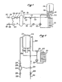
- - la figure 1 montre schématiquement une installation selon un premier mode de réalisation selon l'invention,
- - la figure 2 est une vue schématique d'un deuxième mode de réalisation selon l'invention,
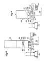
- - la figure 3 montre un appareil selon l'invention.
- - la figure 4 montre un appareil selon un autre mode de réalisation.
- Sur les figures 1 à 4, on peut voir un circuit primaire comportant deux canalisations respectivement d'arrivée 101,201,301,401 et de retour 102,202,302,402. Ces canalisations appartiennent à une chaufferie collective à fluide caloporteur et plus particulièrement à eau chaude, dont la ou les chaudières, telles que 330 et 430 sur les figures 3 et 4, peuvent être de tout type (à charbon, bois, fuel, gaz, ...).
- La canalisation d'arrivée 101,201 est pourvue d'une sonde de température 103,203 et la canalisation de retour 102,202 d'un compteur de consommation thermique 104,204, souvent dénommé compteur de calories.
- La sonde de température 103,203 est reliée audit compteur 104,204 comme le montrent les dessins, tandis que ce dernier est aménagé pour calculer l'énergie dépensée entre l'arrivée et le retour, en fonction du débit et du gradient de température mesuré entre ladite arrivée et ledit retour, Toutefois, il est bien sûr tout à fait envisageable d'utiliser tout autre type de compteur.
- Comme le montrent aussi les figures 1 et 2, on peut prévoir une vanne de barrage 105,205 sur la canalisation d'arrivée et une vanne de barrage 106,206 sur la canalisation de retour, de même qu'une vanne d'isolation compteur 107,207 et un filtre 108,208, ces deux derniers éléments étant aménagés tous deux du côté opposé à la vanne 106,206 par rapport audit compteur 104,204.
- Comme le montrent encore les figures, l'installation comporte en outre un circuit de chauffage pourvu d'une conduite d'entrée 109,209,309,409 et d'une conduite de sortie 110,210,310,410.
- Le circuit de chauffage comporte des corps de chauffe 111,211,311,411 tels que des radiateurs ou des canalisations noyées dans le sol du local à chauffer. Le circuit de chauffage comporte aussi une pompe de circulation 112,212, une vanne mélangeuse 113,213 (automatique ou manuelle) et un thermomètre 120,220.
- Sur le circuit de chauffage précédemment décrit est branché un circuit de réchauffage d'eau sanitaire comportant un ballon d'eau sanitaire 114,214,314 muni d'un échangeur de chaleur dont il sera question ci-après.
- Dans la description qui précède, on peut constater que tous les éléments du mode de réalisation de la figure 1 référencés 101 à 114 se retrouvent quant à leur fonction sur la figure 2 et prennent les références correspondantes 201 à 214, et l'analogie entre ces deux modes de réalisation n'est pas terminée.
- Sur la figure 1, on peut voir que le ballon 114 est muni d'un échangeur 115 qui est branché sur un circuit 116 en parallèle sur le circuit de chauffage 109,110, par l'intermédiaire d'un clapet anti-retour 117 et d'une vanne directionnelle à trois voies 118.
- Dans ce mode de réalisation de la figure 1, on pourrait toutefois prévoir comme déjà dit un autre type d'échangeur, à plaques ou à tubes par exemple, du genre instantané et donc sans ballon.
- L'ensemble du circuit (109,110), d'une part, et 116, d'autre part, forme un circuit dénommé circuit secondaire.
- Le circuit primaire 101,102 et le circuit secondaire précité communiquent entre eux par un conteneur de mélange 119 muni, d'une part, de deux entrées sur lesquelles sont branchées respectivement la canalisation d'arrivée 101 du circuit primaire et la conduite de sortie 110 du circuit de chauffage et, d'autre part, de deux sorties sur lesquelles sont branchées respectivement la canalisation de retour 102 du circuit primaire et la conduite d'entrée 109 du circuit de chauffage. Le conteneur de mélange 119 permet, notamment, d'équilibrer les circuits et de garantir un débit sensiblement constant pour le compteur 104.
- Le mode de réalisation de la figure 2 est tout à fait original. En effet, dans ce mode de réalisation, le conteneur de mélange 119 de la figure 1 est remplacé par une chemise d'eau 219 aménagé autour du ballon 214. On retrouve bien pour cette chemise d'eau les deux entrées sur lesquelles sont branchées respectivement la canalisation d'arrivée 201 du circuit primaire et la conduite de sortie 210 du circuit de chauffage et les deux sorties sur lesquelles sont branchées respectivement la canalisation de retour 202 du circuit primaire et la conduite d'entrée 209 du circuit de chauffage.
- Dans ce mode de réalisation particulier, l'échangeur 115 de la figure 1 est alors constitué par l'enveloppe extérieur du ballon 214 (en inox par exemple) et par la chemise d'eau 219, cette dernière servant aussi, comme déjà dit, de conteneur de mélange.
- On peut aussi noter, à ce stade de la description, que pour assurer de bons mélanges, les entrées dans le conteneur 119 ou 219 sont aménagées à distance de leurs sorties respectives et même à l'opposé en ce qui concerne le mode de réalisation de la figure 2.
- Etant donné la disposition de l'installation de la figure 1, le circuit secondaire est alors pratiquement confondu avec le circuit de chauffage, la chemise 219 étant bien disposée entre les circuits primaire 201,202 et secondaire 209,210.
- Les flèches montrent la circulation de l'eau dans les divers circuits.
- Dans les deux cas (figures 1 et 2), on constate que le compteur 104,204 permet de mesurer la quantité totale d'énergie consommée. La vanne mélangeuse 113,213 permet de régler la température du circuit de chauffage, température mesurée par le thermomètre 120,220.
- Toutefois, dans le cas de la figure 1, le circuit 116 de réchauffage d'eau sanitaire peut être court-circuité à volonté par la vanne directionnelle 118 en cas, par exemple, de dépassement d'une température de consigne, la vanne 118 pouvant être motorisée et commandée à partir d'une sonde de température 121 prévue dans le ballon 116 (la vanne 118 permet généralement l'ouverture, soit du circuit chauffage, soit du circuit de réchauffage d'eau sanitaire).
- On peut remarquer que le circuit de réchauffage d'eau sanitaire est prioritaire dans les deux montages des figures 1 et 2.
- Si dans le mode de réalisation de la figure 2, contrairement à celui de la figure 1, on ne peut pas courtcircuiter le circuit de réchauffage sanitaire de telle sorte que la température dans le ballon 214 n'est pas réglable par l'utilisateur, il est clair qu'il est parfaitement possible d'utiliser, dans ce mode de réalisation, comme dans le premier d'ailleurs, un ou des mitigeurs thermostatiques, réglables ou non par l'utilisateur. Ce ou ces mitigeurs peuvent être aménagés dans le circuit d'eau sanitaire qui comporte, notamment, au moins un conduit d'alimentation 122,222,322,422 et un conduit de retour 123,223,323,423 comme le montrent bien les figures 1 à 4.
- L'invention concerne bien sûr les installations des figures 1 et 2, mais il est clair que ces installations peuvent être agencées de plusieurs manières. L'inventeur a, notamment, imaginé de rassembler tous les organes de commande et de contrôle, y compris l'éventuel mitigeur thermostatique, sous une même carrosserie formant un véritable appareil 324,424, comme le montrent les figures 3 et 4.
- Dans le mode de réalisation de la figure 3, l'appareil 324 est disposé sous le ballon 314, ce qui correspond plutôt à un mode de réalisation du type de l'installation de la figure 1.
- Dans le cas de l'installation de la figure 2, et éventuellement aussi pour celle la figure 1, l'appareil 424 peut avantageusement regrouper sous la même carrosserie l'ensemble des composants et le ballon, comme le montre la figure 4.
- Comme on peut le voir sur les figures 3 et 4, des appareils 324 et 424, n'émergent que les canalisations 301,302; 401,402, les conduites 309,310; 409,410 et les conduits 322,323; 422,423 précédemment décrits (les conduits 322,323 et 422,423 provenant en fait directement du ballon d'eau sanitaire; tous les organes rassemblés dans l'appareil, tels que le conteneur 119 et la vanne 118 (dans le cas de la figure 1), la vanne mélangeuse 113,213, etc, ne sont évidemment pas visibles sur les figures 3 et 4, qui montrent des appareils carrossés.
- Sur les appareils 324 et 424 des figures 3 et 4, on peut voir par contre, un tableau de commande respectivement 325 et 425 qui comporte, par exemple, un bouton de manoeuvre 327,427 de la vanne mélangeuse 113,213, ainsi qu'un cadran de contrôle de température 328,428 qui est asservi au thermomètre 120,220. L'appareil 324 comporte en outre un bouton 326 de commande générale de mise en marche ou d'arrêt de l'installation de chauffage et de production d'eau chaude sanitaire (et par conséquent de tout le circuit secondaire), ce bouton 326 n'existant évidemment pas dans le cas d'un mode de réalisation selon la figure 2. Enfin, le bouton 329,429 sert, par exemple, à commander la mise en marche de la pompe de circulation 112,212, avec deux positions souvent appelées position "été" et position "hiver". En position "été", le bouton 329 de l'appareil 324 autorise la mise en marche de la pompe 112, uniquement pour le réchauffage du ballon 114, alors qu'en position "hiver", ce bouton commande ladite pompe pour le réchauffage du ballon et le chauffage du corps de chauffe 111,311. Le bouton 429 de l'appareil 424, qui est plutôt destiné au mode de réalisation de l'installation de la figure 1, commande selon les positions dites "été" et "hiver", la mise hors service, ou respectivement en fonction, de la pompe 212. D'autres moyens peuvent en outre être prévus, telle, par exemple, qu'une fenêtre 431 pour permettre la lecture du compteur de consommation thermique dans le cas où celui-ci est aménagé dans l'appareil.
Claims (10)
Applications Claiming Priority (2)
| Application Number | Priority Date | Filing Date | Title |
|---|---|---|---|
| FR8813996 | 1988-10-26 | ||
| FR8813996A FR2638223B1 (fr) | 1988-10-26 | 1988-10-26 | Installation et appareil pour le chauffage et la production d'eau chaude sanitaire individuels a partir d'une chaufferie collective |
Publications (2)
| Publication Number | Publication Date |
|---|---|
| EP0368715A1 true EP0368715A1 (fr) | 1990-05-16 |
| EP0368715B1 EP0368715B1 (fr) | 1994-08-10 |
Family
ID=9371293
Family Applications (1)
| Application Number | Title | Priority Date | Filing Date |
|---|---|---|---|
| EP89402959A Expired - Lifetime EP0368715B1 (fr) | 1988-10-26 | 1989-10-26 | Installation et appareil pour le chauffage et la production d'eau chaude sanitaire individuels à partir d'une chaufferie collective |
Country Status (5)
| Country | Link |
|---|---|
| EP (1) | EP0368715B1 (fr) |
| AT (1) | ATE109879T1 (fr) |
| DE (2) | DE68917423T2 (fr) |
| ES (1) | ES2058579T3 (fr) |
| FR (1) | FR2638223B1 (fr) |
Cited By (8)
| Publication number | Priority date | Publication date | Assignee | Title |
|---|---|---|---|---|
| FR2667136A1 (fr) * | 1990-09-21 | 1992-03-27 | Cecid Production | Module de chauffage et de production d'eau chaude sanitaire, et installation de chauffage collectif equipee de tels modules. |
| FR2674941A1 (fr) * | 1991-04-03 | 1992-10-09 | Airelec Ind | Installation pour le chauffage et la production d'eau chaude sanitaire d'un local. |
| EP0626629A3 (fr) * | 1993-05-26 | 1995-02-01 | Mendiguren Santiago Eiguren | Groupe de contrÔle et programmation pour les installations de chauffage à l'eau chaude. |
| AT400759B (de) * | 1993-12-28 | 1996-03-25 | Vaillant Gmbh | Verfahren zur raschen aufheizung eines raumes |
| WO1998008029A1 (fr) * | 1996-08-22 | 1998-02-26 | Kermi Gmbh | Armoire monolithique d'accumulation de chaleur |
| NL1022507C2 (nl) * | 2003-01-27 | 2004-07-28 | Nathan Imp Exp B V | Warmtedistributie-inrichting, alsmede een werkwijze voor het distribueren van warmte. |
| CN101839521A (zh) * | 2010-05-31 | 2010-09-22 | 河北工业大学 | 一种实时热量分摊装置 |
| CN102483245A (zh) * | 2009-04-20 | 2012-05-30 | 乔普-克洛克(苏格兰)有限公司 | 次加热系统控制器 |
Families Citing this family (5)
| Publication number | Priority date | Publication date | Assignee | Title |
|---|---|---|---|---|
| FR2715462B1 (fr) * | 1994-01-27 | 1996-08-09 | Chablais Ste Financiere Cale | Sous-station pour installation combinée de chauffage et de production d'eau chaude sanitaire à partir d'une chaufferie. |
| FR2715461A1 (fr) * | 1994-01-27 | 1995-07-28 | Chablais Ste Financiere Cale | Sous-station pour installation combinée de chauffage et de production d'eau chaude sanitaire à partir d'une chaufferie. |
| FR2725011B1 (fr) * | 1994-09-23 | 1997-08-08 | Financ & Comm Chablais | Ensemble d'equipements pour installation combinee de chauffage et de production d'eau chaude sanitaire |
| DE29713444U1 (de) * | 1997-07-29 | 1997-09-18 | Mannheimer Versorgungs- und Verkehrsgesellschaft mbH (MVV), 68159 Mannheim | Wärmehausstation |
| ES2296559B1 (es) * | 2007-09-13 | 2010-11-02 | Pretensados Zaragoza, S.L. | Bateria de contadores divisionarios de energia. |
Citations (5)
| Publication number | Priority date | Publication date | Assignee | Title |
|---|---|---|---|---|
| FR2475698A1 (fr) * | 1980-02-08 | 1981-08-14 | Acv France Sa | Installation de chauffage urbain et cellule individuelle pour une telle installation |
| DE3123875A1 (de) * | 1980-06-18 | 1982-03-18 | AGA-CTC Värmeväxlare AB, 37201 Ronneby | "abnehmerzentrum fuer bereichsheizsysteme" |
| EP0060011A1 (fr) * | 1981-03-10 | 1982-09-15 | Woningbouwvereniging "TALMA" | Unité de contrôle pour le chauffage central et le chauffage de l'eau sanitaire |
| FR2522788A2 (fr) * | 1982-03-02 | 1983-09-09 | Busseuil Jean Marie | Module hydraulique pour ce comptage et le prelevement d'energie calorifique |
| DE3533160A1 (de) * | 1984-09-20 | 1986-03-20 | Olsson & Nilsson Energikonsult AB, Bara | Steueranordnung |
-
1988
- 1988-10-26 FR FR8813996A patent/FR2638223B1/fr not_active Expired - Lifetime
-
1989
- 1989-10-26 DE DE68917423T patent/DE68917423T2/de not_active Expired - Lifetime
- 1989-10-26 EP EP89402959A patent/EP0368715B1/fr not_active Expired - Lifetime
- 1989-10-26 DE DE8915355U patent/DE8915355U1/de not_active Expired - Lifetime
- 1989-10-26 AT AT89402959T patent/ATE109879T1/de not_active IP Right Cessation
- 1989-10-26 ES ES89402959T patent/ES2058579T3/es not_active Expired - Lifetime
Patent Citations (5)
| Publication number | Priority date | Publication date | Assignee | Title |
|---|---|---|---|---|
| FR2475698A1 (fr) * | 1980-02-08 | 1981-08-14 | Acv France Sa | Installation de chauffage urbain et cellule individuelle pour une telle installation |
| DE3123875A1 (de) * | 1980-06-18 | 1982-03-18 | AGA-CTC Värmeväxlare AB, 37201 Ronneby | "abnehmerzentrum fuer bereichsheizsysteme" |
| EP0060011A1 (fr) * | 1981-03-10 | 1982-09-15 | Woningbouwvereniging "TALMA" | Unité de contrôle pour le chauffage central et le chauffage de l'eau sanitaire |
| FR2522788A2 (fr) * | 1982-03-02 | 1983-09-09 | Busseuil Jean Marie | Module hydraulique pour ce comptage et le prelevement d'energie calorifique |
| DE3533160A1 (de) * | 1984-09-20 | 1986-03-20 | Olsson & Nilsson Energikonsult AB, Bara | Steueranordnung |
Cited By (10)
| Publication number | Priority date | Publication date | Assignee | Title |
|---|---|---|---|---|
| FR2667136A1 (fr) * | 1990-09-21 | 1992-03-27 | Cecid Production | Module de chauffage et de production d'eau chaude sanitaire, et installation de chauffage collectif equipee de tels modules. |
| FR2674941A1 (fr) * | 1991-04-03 | 1992-10-09 | Airelec Ind | Installation pour le chauffage et la production d'eau chaude sanitaire d'un local. |
| EP0626629A3 (fr) * | 1993-05-26 | 1995-02-01 | Mendiguren Santiago Eiguren | Groupe de contrÔle et programmation pour les installations de chauffage à l'eau chaude. |
| AT400759B (de) * | 1993-12-28 | 1996-03-25 | Vaillant Gmbh | Verfahren zur raschen aufheizung eines raumes |
| WO1998008029A1 (fr) * | 1996-08-22 | 1998-02-26 | Kermi Gmbh | Armoire monolithique d'accumulation de chaleur |
| NL1022507C2 (nl) * | 2003-01-27 | 2004-07-28 | Nathan Imp Exp B V | Warmtedistributie-inrichting, alsmede een werkwijze voor het distribueren van warmte. |
| CN102483245A (zh) * | 2009-04-20 | 2012-05-30 | 乔普-克洛克(苏格兰)有限公司 | 次加热系统控制器 |
| CN102483245B (zh) * | 2009-04-20 | 2014-09-17 | 兆平有限公司 | 次加热系统控制器 |
| CN101839521A (zh) * | 2010-05-31 | 2010-09-22 | 河北工业大学 | 一种实时热量分摊装置 |
| CN101839521B (zh) * | 2010-05-31 | 2012-06-13 | 河北工业大学 | 一种实时热量分摊装置 |
Also Published As
| Publication number | Publication date |
|---|---|
| DE8915355U1 (de) | 1990-10-25 |
| FR2638223B1 (fr) | 1991-06-07 |
| FR2638223A1 (fr) | 1990-04-27 |
| DE68917423T2 (de) | 1994-12-01 |
| ATE109879T1 (de) | 1994-08-15 |
| EP0368715B1 (fr) | 1994-08-10 |
| DE68917423D1 (de) | 1994-09-15 |
| ES2058579T3 (es) | 1994-11-01 |
Similar Documents
| Publication | Publication Date | Title |
|---|---|---|
| EP0368715B1 (fr) | Installation et appareil pour le chauffage et la production d'eau chaude sanitaire individuels à partir d'une chaufferie collective | |
| EP0793791B1 (fr) | Appareillage modulaire pour la distribution d'eau chaude et le chauffage d'un immeuble | |
| CH617762A5 (fr) | ||
| EP2837894A1 (fr) | Installation de chauffage d'un circuit d'eau sanitaire et d'un circuit d'eau de chauffage pour une habitation | |
| FR3034505A1 (fr) | Platine de raccord de tuyau, module thermique d’appartement raccorde a une telle platine et installation sanitaire | |
| FR2914048A1 (fr) | Installation de chauffage central hybride et procede de commande d'une telle installation. | |
| FR2920222A1 (fr) | Dispositif de chauffage | |
| FR2464442A1 (fr) | Appareil de chauffage solaire a echangeur de chaleur | |
| FR2645255A1 (fr) | Chaudiere a tubes d'eau et installation de chauffage equipee d'une telle chaudiere | |
| EP1228333B1 (fr) | Chaudiere murale mixte a gaz du type modulaire | |
| FR2725011A1 (fr) | Ensemble d'equipements pour installation combinee de chauffage et de production d'eau chaude sanitaire | |
| FR2536838A1 (fr) | Chaudiere commutable bois/electricite a reserve d'eau chaude integree reliee a une cheminee anti-suie | |
| CH689122A5 (fr) | Installation de chauffage d'eau sanitaire pour la fourniture d'eau chaude et pour le chauffage d'un immeuble. | |
| EP0615099B1 (fr) | Réseau de distribution de fluide à dispositif de régulation | |
| FR3167195A1 (fr) | Système de chauffage comprenant un dispositif de chauffage complémentaire déporté | |
| FR2522788A2 (fr) | Module hydraulique pour ce comptage et le prelevement d'energie calorifique | |
| FR2910600A1 (fr) | Procede de regulation de la puissance d'une installation de fourniture d'eau chaude | |
| FR2762073A1 (fr) | Installation individuelle de chauffage | |
| FR2667136A1 (fr) | Module de chauffage et de production d'eau chaude sanitaire, et installation de chauffage collectif equipee de tels modules. | |
| FR2812378A1 (fr) | Dispositif d'insufflation d'air dans un local | |
| EP0660049B1 (fr) | Méthode et dispositif pour contrÔler une température de liquide | |
| FR2728958A1 (fr) | Installation de chauffage centrale electrique a fluide caloporteur et chaudiere utilisee dans une telle installation | |
| FR2687461A1 (fr) | Systeme thermique semi-collectif a eau chaude pour immeubles d'habitation. | |
| FR2636722A1 (fr) | Installation de chauffage perfectionnee pour habitation avec dispositif de filtration | |
| FR2505458A1 (fr) | Dispositif pour la gestion aeraulique thermique de batiments ainsi que les batiments equipes de ce dispositif |
Legal Events
| Date | Code | Title | Description |
|---|---|---|---|
| PUAI | Public reference made under article 153(3) epc to a published international application that has entered the european phase |
Free format text: ORIGINAL CODE: 0009012 |
|
| AK | Designated contracting states |
Kind code of ref document: A1 Designated state(s): AT BE CH DE ES GB IT LI NL SE |
|
| 17P | Request for examination filed |
Effective date: 19900420 |
|
| 17Q | First examination report despatched |
Effective date: 19910414 |
|
| GRAA | (expected) grant |
Free format text: ORIGINAL CODE: 0009210 |
|
| ITF | It: translation for a ep patent filed | ||
| AK | Designated contracting states |
Kind code of ref document: B1 Designated state(s): AT BE CH DE ES GB IT LI NL SE |
|
| REF | Corresponds to: |
Ref document number: 109879 Country of ref document: AT Date of ref document: 19940815 Kind code of ref document: T |
|
| GBT | Gb: translation of ep patent filed (gb section 77(6)(a)/1977) |
Effective date: 19940805 |
|
| REF | Corresponds to: |
Ref document number: 68917423 Country of ref document: DE Date of ref document: 19940915 |
|
| PG25 | Lapsed in a contracting state [announced via postgrant information from national office to epo] |
Ref country code: LI Effective date: 19941031 Ref country code: CH Effective date: 19941031 |
|
| REG | Reference to a national code |
Ref country code: ES Ref legal event code: FG2A Ref document number: 2058579 Country of ref document: ES Kind code of ref document: T3 |
|
| PG25 | Lapsed in a contracting state [announced via postgrant information from national office to epo] |
Ref country code: SE Effective date: 19941110 |
|
| PLBE | No opposition filed within time limit |
Free format text: ORIGINAL CODE: 0009261 |
|
| STAA | Information on the status of an ep patent application or granted ep patent |
Free format text: STATUS: NO OPPOSITION FILED WITHIN TIME LIMIT |
|
| REG | Reference to a national code |
Ref country code: CH Ref legal event code: PL |
|
| 26N | No opposition filed | ||
| REG | Reference to a national code |
Ref country code: GB Ref legal event code: IF02 |
|
| PGFP | Annual fee paid to national office [announced via postgrant information from national office to epo] |
Ref country code: NL Payment date: 20081015 Year of fee payment: 20 |
|
| PGFP | Annual fee paid to national office [announced via postgrant information from national office to epo] |
Ref country code: ES Payment date: 20081003 Year of fee payment: 20 Ref country code: AT Payment date: 20081015 Year of fee payment: 20 Ref country code: BE Payment date: 20080917 Year of fee payment: 20 |
|
| PGFP | Annual fee paid to national office [announced via postgrant information from national office to epo] |
Ref country code: IT Payment date: 20081027 Year of fee payment: 20 |
|
| PGFP | Annual fee paid to national office [announced via postgrant information from national office to epo] |
Ref country code: DE Payment date: 20081218 Year of fee payment: 20 |
|
| PGFP | Annual fee paid to national office [announced via postgrant information from national office to epo] |
Ref country code: GB Payment date: 20081016 Year of fee payment: 20 |
|
| BE20 | Be: patent expired |
Owner name: S.A. *GEMINOX Effective date: 20091026 |
|
| REG | Reference to a national code |
Ref country code: GB Ref legal event code: PE20 Expiry date: 20091025 |
|
| REG | Reference to a national code |
Ref country code: ES Ref legal event code: FD2A Effective date: 20091027 |
|
| NLV7 | Nl: ceased due to reaching the maximum lifetime of a patent |
Effective date: 20091026 |
|
| PG25 | Lapsed in a contracting state [announced via postgrant information from national office to epo] |
Ref country code: ES Free format text: LAPSE BECAUSE OF EXPIRATION OF PROTECTION Effective date: 20091027 |
|
| PG25 | Lapsed in a contracting state [announced via postgrant information from national office to epo] |
Ref country code: NL Free format text: LAPSE BECAUSE OF EXPIRATION OF PROTECTION Effective date: 20091026 |
|
| PG25 | Lapsed in a contracting state [announced via postgrant information from national office to epo] |
Ref country code: GB Free format text: LAPSE BECAUSE OF EXPIRATION OF PROTECTION Effective date: 20091025 |