EP0368720A1 - Element einer als Dampfsperre dienenden Isolierwand, insbesondere für Klimakammer - Google Patents
Element einer als Dampfsperre dienenden Isolierwand, insbesondere für Klimakammer Download PDFInfo
- Publication number
- EP0368720A1 EP0368720A1 EP89402979A EP89402979A EP0368720A1 EP 0368720 A1 EP0368720 A1 EP 0368720A1 EP 89402979 A EP89402979 A EP 89402979A EP 89402979 A EP89402979 A EP 89402979A EP 0368720 A1 EP0368720 A1 EP 0368720A1
- Authority
- EP
- European Patent Office
- Prior art keywords
- wall element
- panel
- element according
- insulating wall
- faces
- Prior art date
- Legal status (The legal status is an assumption and is not a legal conclusion. Google has not performed a legal analysis and makes no representation as to the accuracy of the status listed.)
- Withdrawn
Links
- 230000004888 barrier function Effects 0.000 title claims description 26
- 238000009413 insulation Methods 0.000 title claims description 3
- 239000011810 insulating material Substances 0.000 claims abstract description 27
- 230000001413 cellular effect Effects 0.000 claims abstract description 5
- 238000004519 manufacturing process Methods 0.000 claims abstract description 5
- 229920005989 resin Polymers 0.000 claims abstract description 4
- 239000011347 resin Substances 0.000 claims abstract description 4
- 230000002787 reinforcement Effects 0.000 claims description 11
- 239000000463 material Substances 0.000 claims description 5
- 230000002093 peripheral effect Effects 0.000 claims description 4
- 238000000465 moulding Methods 0.000 claims description 3
- 238000004026 adhesive bonding Methods 0.000 claims description 2
- 229910052782 aluminium Inorganic materials 0.000 claims description 2
- XAGFODPZIPBFFR-UHFFFAOYSA-N aluminium Chemical compound [Al] XAGFODPZIPBFFR-UHFFFAOYSA-N 0.000 claims description 2
- 238000001125 extrusion Methods 0.000 claims description 2
- XLYOFNOQVPJJNP-UHFFFAOYSA-N water Substances O XLYOFNOQVPJJNP-UHFFFAOYSA-N 0.000 description 3
- 230000000903 blocking effect Effects 0.000 description 2
- 238000005336 cracking Methods 0.000 description 2
- 239000000835 fiber Substances 0.000 description 2
- 238000000034 method Methods 0.000 description 2
- 238000005192 partition Methods 0.000 description 2
- 239000011248 coating agent Substances 0.000 description 1
- 238000000576 coating method Methods 0.000 description 1
- 229940082150 encore Drugs 0.000 description 1
- 229910052500 inorganic mineral Inorganic materials 0.000 description 1
- 239000012212 insulator Substances 0.000 description 1
- 238000005304 joining Methods 0.000 description 1
- 229910052751 metal Inorganic materials 0.000 description 1
- 239000002184 metal Substances 0.000 description 1
- 239000011707 mineral Substances 0.000 description 1
- 229920003002 synthetic resin Polymers 0.000 description 1
- 239000000057 synthetic resin Substances 0.000 description 1
- 239000004753 textile Substances 0.000 description 1
- 230000003313 weakening effect Effects 0.000 description 1
Images
Classifications
-
- F—MECHANICAL ENGINEERING; LIGHTING; HEATING; WEAPONS; BLASTING
- F16—ENGINEERING ELEMENTS AND UNITS; GENERAL MEASURES FOR PRODUCING AND MAINTAINING EFFECTIVE FUNCTIONING OF MACHINES OR INSTALLATIONS; THERMAL INSULATION IN GENERAL
- F16L—PIPES; JOINTS OR FITTINGS FOR PIPES; SUPPORTS FOR PIPES, CABLES OR PROTECTIVE TUBING; MEANS FOR THERMAL INSULATION IN GENERAL
- F16L59/00—Thermal insulation in general
- F16L59/02—Shape or form of insulating materials, with or without coverings integral with the insulating materials
-
- E—FIXED CONSTRUCTIONS
- E04—BUILDING
- E04B—GENERAL BUILDING CONSTRUCTIONS; WALLS, e.g. PARTITIONS; ROOFS; FLOORS; CEILINGS; INSULATION OR OTHER PROTECTION OF BUILDINGS
- E04B1/00—Constructions in general; Structures which are not restricted either to walls, e.g. partitions, or floors or ceilings or roofs
- E04B1/62—Insulation or other protection; Elements or use of specified material therefor
- E04B1/74—Heat, sound or noise insulation, absorption, or reflection; Other building methods affording favourable thermal or acoustical conditions, e.g. accumulating of heat within walls
- E04B1/76—Heat, sound or noise insulation, absorption, or reflection; Other building methods affording favourable thermal or acoustical conditions, e.g. accumulating of heat within walls specifically with respect to heat only
- E04B1/78—Heat insulating elements
- E04B1/80—Heat insulating elements slab-shaped
-
- E—FIXED CONSTRUCTIONS
- E04—BUILDING
- E04C—STRUCTURAL ELEMENTS; BUILDING MATERIALS
- E04C2/00—Building elements of relatively thin form for the construction of parts of buildings, e.g. sheet materials, slabs, or panels
- E04C2/02—Building elements of relatively thin form for the construction of parts of buildings, e.g. sheet materials, slabs, or panels characterised by specified materials
- E04C2/26—Building elements of relatively thin form for the construction of parts of buildings, e.g. sheet materials, slabs, or panels characterised by specified materials composed of materials covered by two or more of groups E04C2/04, E04C2/08, E04C2/10 or of materials covered by one of these groups with a material not specified in one of the groups
- E04C2/284—Building elements of relatively thin form for the construction of parts of buildings, e.g. sheet materials, slabs, or panels characterised by specified materials composed of materials covered by two or more of groups E04C2/04, E04C2/08, E04C2/10 or of materials covered by one of these groups with a material not specified in one of the groups at least one of the materials being insulating
- E04C2/292—Building elements of relatively thin form for the construction of parts of buildings, e.g. sheet materials, slabs, or panels characterised by specified materials composed of materials covered by two or more of groups E04C2/04, E04C2/08, E04C2/10 or of materials covered by one of these groups with a material not specified in one of the groups at least one of the materials being insulating composed of insulating material and sheet metal
Definitions
- the present invention relates to the production of an insulating wall for a climatic chamber or a cryogenic tunnel.
- a climatic chamber is a sealed enclosure in which the aerodynamic characteristics of certain equipment, such as motor cars, tanks, planes, space shuttles, are tested. Reduced models of these devices are used for this purpose. So that the conditions of experimentation on the model are identical to those which prevail on the real model, it is necessary that the number of Reynolds Re is the same in both cases.
- Re VD ⁇ / ⁇
- D the air flow velocity
- ⁇ the density of the air
- ⁇ the dynamic coefficient of air.
- the density must be increased. It is therefore necessary to operate in an atmosphere at low temperature and at low pressure, for example at a temperature of approximately 70 ° K and at a pressure of 4 to 5 bars. Maintaining such operating conditions requires that the chamber be perfectly isolated from the outside environment.
- the side wall of a climatic chamber is generally constituted by a metallic ferrule of cylindrical shape, internally coated with a layer of insulating material, for example in any cellular product.
- a layer of insulating material for example in any cellular product.
- An object of the present invention is therefore to provide an vapor barrier insulating wall for a climatic chamber which is capable of preventing water from leaving the insulator.
- Another object of the invention is to propose a climate chamber wall capable of ensuring good thermal insulation under operating conditions, i.e. for an internal temperature of 70 ° K and an external temperature of 300 ° K.
- a third goal is to produce a wall which retains good mechanical resistance to the experimental temperature.
- the insulating material contracts under the action of the low internal temperature to which it is subjected and cracks, thus losing some of its characteristics. .
- the climatic chambers according to the prior art have a metallic skin which covers the inner face of the layer of insulating material constituting the wall.
- This skin is mainly used to give a smooth appearance to the side wall and thereby promote good air flow.
- the skin is provided on its outer face with rods of material which is not very conductive of heat, which pass through the layer of insulating material and will seek a grip on the outer shell.
- rods of material which is not very conductive of heat, which pass through the layer of insulating material and will seek a grip on the outer shell.
- a fourth object of the invention is therefore to produce a wall for a climatic chamber free from this latter drawback, that is to say which does not have zones of weakening of the insulating layer, due to the fixing of a skin.
- the vapor barrier wall element according to the invention which is characterized in that it comprises at least one thickness of insulating material, for example in a cellular product, taken into account. sandwich inside a hollow and waterproof panel, made of a resin reinforced with fibers, and provided with a rabbet along its edge, intended for assembly with neighboring panels, a vapor barrier complex being integrated into the panel during manufacturing, so as to wrap the insulating material on all its faces.
- the lateral faces of the panel are interconnected by several bridges or frames defining in the panel compartments filled with independent blocks of insulating material.
- the reinforcements can be perpendicular to the two lateral faces and extend over the entire height of the panel, the insulating blocks then being in the form of parallelepipedic bars with square or rectangular section. However, they can also be inclined relative to the lateral faces, alternately in one direction and in the other from one reinforcement to the next, which leads to insulating blocks having a trapezoidal section.
- a wall element by superimposing at least two sandwich panels of the same dimensions and devoid of rebate, with a slight offset from one in relation to the other in the diagonal direction so as to reveal a peripheral rebate, and by joining them together, for example by gluing their contiguous faces or by an appropriate mechanical fixing.
- Each block of material can be wrapped separately in a vapor barrier sheet.
- the blocks of insulating material can also be inserted in their compartment without vapor barrier, the vapor barrier function then being ensured by a vapor barrier sheet which envelops the panel on all its faces or which is integrated in the thickness. panel wall.
- the panel has a mechanical resistance much higher than that of a panel of the same dimensions, made of the same material, but not enclosing any insulating material.
- the vapor barrier function is closely linked to the panel thanks to the presence of the vapor barrier sheet (s) which envelopes the block (s) of insulating material on all of its (their) faces.
- the reinforcements make it possible to absorb the dimensional variations of the blocks of insulating material and to block them in position. This eliminates the problems due to cracking of the insulating material.
- the invention therefore provides a prefabricated climatic chamber panel, which alone fulfills all the functions, and which is therefore ready for assembly.
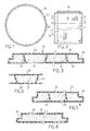
- the climatic chamber represented in FIG. 1 comprises a side wall constituted by a sealed metallic ferrule 10 of cylindrical shape, but which can also be parallelepiped.
- the ferrule rests on the ground and is closed at its upper end by a ceiling, not shown.
- the walls of the chamber are insulated by means of an insulating coating 12 applied to the interior face of the shell.
- the covering consists of juxtaposed wall elements 14, one of which is shown in detail in FIGS. 2 and 3.
- the wall element 14 has a sandwich structure comprising a hollow panel, of substantially shaped parallelepiped and made of a synthetic resin, reinforced with fibers, for example mineral or textile, in order to increase its mechanical resistance.
- Said panel is provided with two flat or curved faces 16, 18 depending on the shape of the shell on which they are fitted, which are connected by a plurality of bridges or frames 20 extending over the entire height of the panel.
- the reinforcements come from manufacture with said lateral faces, for example during a molding or extrusion operation.
- the frames are inclined on the faces 16, 18, alternately in one direction or the other, so as to define between them passages of trapezoidal section.
- These passages house bars of the same shape, made of an insulating material 22, for example of a cellular product.
- the reinforcements can be perpendicular to the faces 16, 18.
- the blocks of material will have a square or rectangular section.
- the reinforced resin is not waterproof against water vapor, it is necessary to use a vapor barrier to prevent the residual vapor present in the blocks of insulating material from migrating towards the interior of the climatic chamber , at the risk of distorting the aerodynamic conditions of the model tested
- the vapor barrier is constituted for example by a complex based on metallic and organic sheets of very small thickness, for example aluminum and polytraphthalate.
- each block 22 of insulating material is individually wrapped on all its faces, including on its end faces, by a vapor barrier sheet.
- the panel 16 is provided with a peripheral rebate 26 making it possible to assemble the panels together, as will be explained below.
- the rebate also has a hollow sandwich structure and is filled with a block of insulating material of suitable shape, wrapped in a vapor barrier sheet.
- FIG. 4 differs from that of FIG. 2 only in that, instead of wrapping each block of insulating material with a vapor barrier sheet, integrated vapor barrier sheets 28, 30 are used. during molding in the faces 16, 18 of the panel. Note that it is not necessary to integrate vapor barrier sheets in the reinforcements 20, as long as the vapor is trapped between the sheets 28,30.
- a single vapor barrier sheet 24 envelops the panel outwardly.
- the panel according to FIG. 6 differs from that of FIG. 2 by the fact that it does not include reinforcements.
- the panel consists of two separate rectangular panels 32, 32 'of the type illustrated in Figure 2, but having no rebate. These panels are superimposed by slightly shifting them in the diagonal direction with respect to each other so as to reveal a peripheral rebate 26, and are secured by any known means.
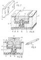
- Two panels 14, 14 ′ are applied side by side against the interior wall of the shell 10 with their vertical sides (FIG. 2) oriented in the direction of the height of the ferrule and their rebates 26 facing the interior of the ferrule.
- the two panels are arranged on either side of a vertical row of threaded rods 34 welded to the ferrule, a single threaded rod being shown in Figure 8.
- On said rod is screwed the hollow head of a stud 36 which protrudes into the channel formed by the two rebates 26.
- On the stud is threaded a washer 38 which bears on the rebates.
- a nut 40 is then screwed onto the stud portion projecting above the washer, thus ensuring an energetic blocking of the panels on the ferrule.
- the nut is then capped with a wedge 42, and finally, the channel formed between the panels receives a strip 44 which exactly fills the channel and whose outer wall comes exactly flush with those of the two panels.
- the strip has on its outer face notches 46 intended to receive the nuts 40.
- the threaded rod of the stud 36 is long enough for it to emerge outside the channel formed by the rebates 26.
- the rod passes through a washer 38 and a nut of blocking 40, but in the present case, it also passes through a wedge 42, an insert of insulating material 48 fixed in a hole drilled in the strip 44 and a hole drilled in a profile 50 intended for fixing objects on the interior wall of the climatic chamber.
- the profile is fixed by means of tapped sockets 52 aimed at the stud.
- a ready-to-assemble panel is provided, integrating into it all the functions of an insulating panel for a climatic chamber, without the need to add other elements to it.
Landscapes
- Engineering & Computer Science (AREA)
- Architecture (AREA)
- Physics & Mathematics (AREA)
- Civil Engineering (AREA)
- Structural Engineering (AREA)
- General Engineering & Computer Science (AREA)
- Acoustics & Sound (AREA)
- Electromagnetism (AREA)
- Mechanical Engineering (AREA)
- Thermal Insulation (AREA)
- Building Environments (AREA)
Applications Claiming Priority (2)
| Application Number | Priority Date | Filing Date | Title |
|---|---|---|---|
| FR8814708A FR2638814B1 (fr) | 1988-11-10 | 1988-11-10 | Element de paroi isolante pare-vapeur, notamment pour chambre climatique |
| FR8814708 | 1988-11-10 |
Publications (1)
| Publication Number | Publication Date |
|---|---|
| EP0368720A1 true EP0368720A1 (de) | 1990-05-16 |
Family
ID=9371778
Family Applications (1)
| Application Number | Title | Priority Date | Filing Date |
|---|---|---|---|
| EP89402979A Withdrawn EP0368720A1 (de) | 1988-11-10 | 1989-10-27 | Element einer als Dampfsperre dienenden Isolierwand, insbesondere für Klimakammer |
Country Status (2)
| Country | Link |
|---|---|
| EP (1) | EP0368720A1 (de) |
| FR (1) | FR2638814B1 (de) |
Cited By (1)
| Publication number | Priority date | Publication date | Assignee | Title |
|---|---|---|---|---|
| EP0498778A1 (de) * | 1991-02-08 | 1992-08-12 | Angelantoni Climatic Systems - S.P.A. | Modulare Fussbodenplatten für die Herstellung von Klimakammern |
Families Citing this family (1)
| Publication number | Priority date | Publication date | Assignee | Title |
|---|---|---|---|---|
| CA3197419A1 (en) * | 2022-11-22 | 2024-05-22 | 1947742 Alberta Ltd. | Wall panel and method for constructing a wall |
Citations (5)
| Publication number | Priority date | Publication date | Assignee | Title |
|---|---|---|---|---|
| CA434654A (en) * | 1946-05-14 | L. Despain Augustus | Bundle trimmer mechanism | |
| US3289624A (en) * | 1965-01-18 | 1966-12-06 | Exxon Research Engineering Co | Plastic barge for cryogenic service |
| US3339780A (en) * | 1964-11-06 | 1967-09-05 | Exxon Research Engineering Co | Duplex insulating panel |
| US3998024A (en) * | 1975-08-04 | 1976-12-21 | H. H. Robertson Company | Double-skin insulated building panel |
| GB2011837A (en) * | 1978-01-09 | 1979-07-18 | Becker Wilhelm Ab | Improvements in or Relating to a Heat Insulating Member |
Family Cites Families (1)
| Publication number | Priority date | Publication date | Assignee | Title |
|---|---|---|---|---|
| DE1295172B (de) * | 1964-07-15 | 1969-05-14 | Rohpappenfabrik Worms | Bauplatte aus allseitig von Schaumkunststoff umgebenen Versteifungskoerpern |
-
1988
- 1988-11-10 FR FR8814708A patent/FR2638814B1/fr not_active Expired - Fee Related
-
1989
- 1989-10-27 EP EP89402979A patent/EP0368720A1/de not_active Withdrawn
Patent Citations (5)
| Publication number | Priority date | Publication date | Assignee | Title |
|---|---|---|---|---|
| CA434654A (en) * | 1946-05-14 | L. Despain Augustus | Bundle trimmer mechanism | |
| US3339780A (en) * | 1964-11-06 | 1967-09-05 | Exxon Research Engineering Co | Duplex insulating panel |
| US3289624A (en) * | 1965-01-18 | 1966-12-06 | Exxon Research Engineering Co | Plastic barge for cryogenic service |
| US3998024A (en) * | 1975-08-04 | 1976-12-21 | H. H. Robertson Company | Double-skin insulated building panel |
| GB2011837A (en) * | 1978-01-09 | 1979-07-18 | Becker Wilhelm Ab | Improvements in or Relating to a Heat Insulating Member |
Cited By (1)
| Publication number | Priority date | Publication date | Assignee | Title |
|---|---|---|---|---|
| EP0498778A1 (de) * | 1991-02-08 | 1992-08-12 | Angelantoni Climatic Systems - S.P.A. | Modulare Fussbodenplatten für die Herstellung von Klimakammern |
Also Published As
| Publication number | Publication date |
|---|---|
| FR2638814A1 (fr) | 1990-05-11 |
| FR2638814B1 (fr) | 1991-02-15 |
Similar Documents
| Publication | Publication Date | Title |
|---|---|---|
| CA2674264C (fr) | Section de fuselage pour aeronef et aeronef comprenant une telle section | |
| FR2724623A1 (fr) | Cuve etanche et thermiquement isolante perfectionnee integree dans une structure porteuse | |
| EP0022384A1 (de) | Verfahren zur Konstruktion eines Speichertanks für Flüssigkeiten bei niedrigen Temperaturen und der erhaltene Tank | |
| WO2012084874A9 (fr) | Dispositif d'isolation thermique mince à haute performance | |
| FR3012111A1 (fr) | Fuselage d'aeronef comprenant une isolation externe | |
| EP0309358B1 (de) | Verfahren zum Zusammenbau von Paneelen eines Fahrzeugaufbaus und Profil für die Durchführung dieses Verfahrens | |
| WO2015155438A1 (fr) | Ensemble d'isolation thermique incluant des panneaux piv et procédé d'assemblage d'un tel ensemble | |
| FR2552153A1 (fr) | Element pour porte ou fenetre ou panneau-facade constitue notamment de deux panneaux plans separes par un gaz a variation de volume compensee | |
| EP3592630B1 (de) | Struktur für eine motorfahrzeugkarosserie | |
| EP2412613B1 (de) | Karosseriemodul für ein Kühlfahrzeug mit Vakuum-Isolierpaneel, und entsprechendes Herstellungsverfahren | |
| EP0368720A1 (de) | Element einer als Dampfsperre dienenden Isolierwand, insbesondere für Klimakammer | |
| FR2635603A1 (fr) | Paroi interieure d'absorption acoustique | |
| FR2940785A1 (fr) | Jonction longitudinale pour panneaux de fuselage d'aeronef en materiaux composites | |
| FR2991250A1 (fr) | Module de carrosserie pour vehicule frigorifique comprenant un panneau d'isolation sous vide, et procede de fabrication associe. | |
| EP2860320B1 (de) | Wärmeisolierter Boden mit Vakuumisolationspaneelen (VIP), Bodenmodul und Montage-Kit | |
| EP2582891B1 (de) | Anordnung mit mindestens einer bauplatte mit mindestens einem darin integrierten distanzstück und verfahren zur montage der anordnung | |
| FR2515798A1 (fr) | Refrigerateur | |
| FR2820158A1 (fr) | Dispositif de rupture de pont thermique pour profile metallique | |
| FR2470213A1 (fr) | Dispositif de dalle legere, fonctionnelle pour la construction | |
| FR2539784A1 (fr) | Panneau d'isolation thermique et phonique | |
| FR2960048A1 (fr) | Paroi formee d'une pluralite de panneaux solaires juxtaposes, comportant des moyens d'isolation thermique, et procede de fabrication d'une telle paroi | |
| FR2481785A1 (fr) | Surfaces pour capteur solaire | |
| FR2799489A1 (fr) | Element de cloture en metal ou en matiere plastique | |
| FR3020308B1 (fr) | Panneau sandwich comprenant deux couches d'absorption de deformations mecaniques | |
| FR2539166A1 (fr) | Panneau de construction, par exemple panneau de porte |
Legal Events
| Date | Code | Title | Description |
|---|---|---|---|
| PUAI | Public reference made under article 153(3) epc to a published international application that has entered the european phase |
Free format text: ORIGINAL CODE: 0009012 |
|
| AK | Designated contracting states |
Kind code of ref document: A1 Designated state(s): BE DE ES GB GR IT LU NL |
|
| 17P | Request for examination filed |
Effective date: 19900717 |
|
| 17Q | First examination report despatched |
Effective date: 19910222 |
|
| STAA | Information on the status of an ep patent application or granted ep patent |
Free format text: STATUS: THE APPLICATION IS DEEMED TO BE WITHDRAWN |
|
| 18D | Application deemed to be withdrawn |
Effective date: 19910705 |