EP0368723A1 - Verbindungsvorrichtung für zwei Elemente - Google Patents
Verbindungsvorrichtung für zwei Elemente Download PDFInfo
- Publication number
- EP0368723A1 EP0368723A1 EP89403002A EP89403002A EP0368723A1 EP 0368723 A1 EP0368723 A1 EP 0368723A1 EP 89403002 A EP89403002 A EP 89403002A EP 89403002 A EP89403002 A EP 89403002A EP 0368723 A1 EP0368723 A1 EP 0368723A1
- Authority
- EP
- European Patent Office
- Prior art keywords
- axis
- fastening device
- face
- hole
- wing
- Prior art date
- Legal status (The legal status is an assumption and is not a legal conclusion. Google has not performed a legal analysis and makes no representation as to the accuracy of the status listed.)
- Granted
Links
Images

Classifications
-
- F—MECHANICAL ENGINEERING; LIGHTING; HEATING; WEAPONS; BLASTING
- F16—ENGINEERING ELEMENTS AND UNITS; GENERAL MEASURES FOR PRODUCING AND MAINTAINING EFFECTIVE FUNCTIONING OF MACHINES OR INSTALLATIONS; THERMAL INSULATION IN GENERAL
- F16B—DEVICES FOR FASTENING OR SECURING CONSTRUCTIONAL ELEMENTS OR MACHINE PARTS TOGETHER, e.g. NAILS, BOLTS, CIRCLIPS, CLAMPS, CLIPS OR WEDGES; JOINTS OR JOINTING
- F16B5/00—Joining sheets or plates, e.g. panels, to one another or to strips or bars parallel to them
- F16B5/06—Joining sheets or plates, e.g. panels, to one another or to strips or bars parallel to them by means of clamps or clips
- F16B5/0607—Joining sheets or plates, e.g. panels, to one another or to strips or bars parallel to them by means of clamps or clips joining sheets or plates to each other
- F16B5/0621—Joining sheets or plates, e.g. panels, to one another or to strips or bars parallel to them by means of clamps or clips joining sheets or plates to each other in parallel relationship
- F16B5/0642—Joining sheets or plates, e.g. panels, to one another or to strips or bars parallel to them by means of clamps or clips joining sheets or plates to each other in parallel relationship the plates being arranged one on top of the other and in full close contact with each other
-
- F—MECHANICAL ENGINEERING; LIGHTING; HEATING; WEAPONS; BLASTING
- F16—ENGINEERING ELEMENTS AND UNITS; GENERAL MEASURES FOR PRODUCING AND MAINTAINING EFFECTIVE FUNCTIONING OF MACHINES OR INSTALLATIONS; THERMAL INSULATION IN GENERAL
- F16B—DEVICES FOR FASTENING OR SECURING CONSTRUCTIONAL ELEMENTS OR MACHINE PARTS TOGETHER, e.g. NAILS, BOLTS, CIRCLIPS, CLAMPS, CLIPS OR WEDGES; JOINTS OR JOINTING
- F16B13/00—Dowels or other devices fastened in walls or the like by inserting them in holes made therein for that purpose
- F16B13/04—Dowels or other devices fastened in walls or the like by inserting them in holes made therein for that purpose with parts gripping in the hole or behind the reverse side of the wall after inserting from the front
- F16B13/08—Dowels or other devices fastened in walls or the like by inserting them in holes made therein for that purpose with parts gripping in the hole or behind the reverse side of the wall after inserting from the front with separate or non-separate gripping parts moved into their final position in relation to the body of the device without further manual operation
- F16B13/0808—Dowels or other devices fastened in walls or the like by inserting them in holes made therein for that purpose with parts gripping in the hole or behind the reverse side of the wall after inserting from the front with separate or non-separate gripping parts moved into their final position in relation to the body of the device without further manual operation by a toggle-mechanism
Definitions
- the present invention relates to a device for attaching two elements.
- the object of the present invention is to provide an assembly device which is insensitive to corrosion and which guarantees effective blocking over time.
- the device for attaching two elements comprises a pin cooperating with a support spacer.
- the pin consists of a head and an axis provided with at least two holding wings which are articulated on a flange, so that after the introduction, the passage and the passing of the head through the two holes, said retaining wings open around the flange to come to bear against the underside of the element; the support spacer being retracted, firstly, in the axis then introduced into the hole of the element to come and block the assembly by means of a closure end made on the axis.
- the flanges have a locking face which cooperates with a conjugate shape of the internal end of each retaining wing.
- Each retaining wing has an elastic blade arranged on its internal face, with which it is perpendicular; of so as to stress during engagement, and then come parallel to the axis to ensure centering.
- the axis is provided with notches, which cooperate with at least one set of two notches arranged in the spacer.
- the present invention thus has the advantage of offering a device for attaching two elements, which allows rapid assembly which is insensitive to corrosion with good support which remains effective over time.
- the device for attaching two elements according to the invention thus has the advantage of facilitating the mounting of the pin and guaranteeing the blocking of the support spacer.
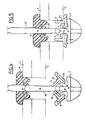
- the attachment device connects two elements 1 and 2, the element, the element 1 being above the element 2 in FIG. 2.
- the element 1 has a hole 3, which is aligned with a hole 4 belonging to element 2.
- the attachment device consists of a pin 5 which cooperates with a support spacer 6.
- the pin 5 has an axis 8 which ends in a head 7.
- the axis 8 is equipped with 3 holding wings 9 which are 'articulate on a flange 10 arranged on said axis 8.
- the head 7 has a frustoconical shape with a rounded end so as to facilitate its introduction into the holes 3 and 4.
- the flange 10 has a locking face 13 which makes an acute angle relative to the axis 8. This locking face 13 cooperates with the conjugate shape of the internal end of each retaining wing 9, which rests on it .
- Each retaining wing 9 has a protuberance 15 which has an outer face in the shape of an arc of a circle, the diameter of which is slightly smaller than the diameter of the holes 3 or 4, so that it can come to center in the hole 4 of item 2.
- each retaining wing has a rounded 16 on its outer end in order to facilitate the sliding of the retaining wing 9 against the underside 11 of the element 2 during the opening of said retaining wing 9.
- the spacer 6 has a frustoconical shape to allow the introduction and self-centering in the hole 3 of the corresponding element 1.
- This frustoconical shape is extended by a cylindrical shape with a diameter slightly smaller than the diameter of the holes 3 or 4.
- the pin 5 is successively introduced into the holes 3 and 4 so that the head 7 passes through and exceeds the said holes until the retaining wings 9 open around the flange 10 to come to bear against the underside 11 of element 2.
- the support spacer 6 is retracted, in a first step, in the axis 8, by means of its hole 18 then, in a second step, it is introduced into the hole 3 of the element 1 by means of its frustoconical shape, so that the cylindrical shape, which extends it, comes to fit in said hole 3.
- the support spacer 6 is blocked by means of its face 17 of its base 19, against the upper face 20 of the element 1.
- the support spacer 6 is blocked by a closing end 12 formed on the axis 8.
- the closing end 12 is obtained by flaring the axis 8 by means of an appropriate tool.
- the closing end 12 is constituted by a washer comprising a blocking imprint on the axis 8.
- the flange 10 arranged on the axis 8 extends along said axis 8 and has a locking face 21 which is arranged around the axis 8 and perpendicular thereto. This locking face 21 cooperates with a conjugate shape 22 of the internal end 14 of each retaining wing 9.
- Each retaining wing 9 has an elastic blade 23 which is arranged on its internal face with which it is perpendicular. During assembly, that is to say during movement in the holes 3 and 4, the elastic blades 23 put themselves under stress against the axis 8.
- the elastic blades 23 are released and come to be located parallel to the axis 8.
- the elastic blades 23 are then centered in the hole 4 of the element 2 by means of d '' an external boss 25.
- the axis 8 is provided with notches 26 located face to face, which cooperate with one or more sets of two notches 27 also arranged face to face in the support spacer 6.
Landscapes
- Engineering & Computer Science (AREA)
- General Engineering & Computer Science (AREA)
- Mechanical Engineering (AREA)
- Insertion Pins And Rivets (AREA)
- Snaps, Bayonet Connections, Set Pins, And Snap Rings (AREA)
- Clamps And Clips (AREA)
- Mutual Connection Of Rods And Tubes (AREA)
- Connection Of Plates (AREA)
Applications Claiming Priority (4)
| Application Number | Priority Date | Filing Date | Title |
|---|---|---|---|
| FR8814545 | 1988-11-08 | ||
| FR8814545A FR2638795B1 (fr) | 1988-11-08 | 1988-11-08 | Dispositif d'attache de deux elements |
| FR8900782A FR2642119B2 (fr) | 1988-11-08 | 1989-01-24 | Dispositif d'attache de deux elements |
| FR8900782 | 1989-01-24 |
Publications (2)
| Publication Number | Publication Date |
|---|---|
| EP0368723A1 true EP0368723A1 (de) | 1990-05-16 |
| EP0368723B1 EP0368723B1 (de) | 1992-05-20 |
Family
ID=26226972
Family Applications (1)
| Application Number | Title | Priority Date | Filing Date |
|---|---|---|---|
| EP19890403002 Expired - Lifetime EP0368723B1 (de) | 1988-11-08 | 1989-10-31 | Verbindungsvorrichtung für zwei Elemente |
Country Status (4)
| Country | Link |
|---|---|
| EP (1) | EP0368723B1 (de) |
| DE (1) | DE68901605D1 (de) |
| ES (1) | ES2031698T3 (de) |
| FR (1) | FR2642119B2 (de) |
Cited By (1)
| Publication number | Priority date | Publication date | Assignee | Title |
|---|---|---|---|---|
| US5094563A (en) * | 1990-02-02 | 1992-03-10 | Societe Nationale D'etude Et De Construction De Moteurs D'aviation "S.N.E.C.M.A." | Spacer for a fixing to a panel of hollow or sandwich construction |
Citations (5)
| Publication number | Priority date | Publication date | Assignee | Title |
|---|---|---|---|---|
| US2758498A (en) * | 1953-12-17 | 1956-08-14 | Speed Stud Corp | Threadless snap fastener with solid reinforcing core therein |
| GB1287818A (de) * | 1969-04-23 | 1972-09-06 | ||
| US3722037A (en) * | 1971-08-23 | 1973-03-27 | Illinois Tool Works | Locating plug |
| DE3427640A1 (de) * | 1984-07-26 | 1986-02-06 | Bayerische Motoren Werke AG, 8000 München | Schraube |
| US4657461A (en) * | 1984-10-26 | 1987-04-14 | Smith Gareth J | Anchoring bolt |
-
1989
- 1989-01-24 FR FR8900782A patent/FR2642119B2/fr not_active Expired - Lifetime
- 1989-10-31 ES ES89403002T patent/ES2031698T3/es not_active Expired - Lifetime
- 1989-10-31 DE DE8989403002T patent/DE68901605D1/de not_active Expired - Lifetime
- 1989-10-31 EP EP19890403002 patent/EP0368723B1/de not_active Expired - Lifetime
Patent Citations (5)
| Publication number | Priority date | Publication date | Assignee | Title |
|---|---|---|---|---|
| US2758498A (en) * | 1953-12-17 | 1956-08-14 | Speed Stud Corp | Threadless snap fastener with solid reinforcing core therein |
| GB1287818A (de) * | 1969-04-23 | 1972-09-06 | ||
| US3722037A (en) * | 1971-08-23 | 1973-03-27 | Illinois Tool Works | Locating plug |
| DE3427640A1 (de) * | 1984-07-26 | 1986-02-06 | Bayerische Motoren Werke AG, 8000 München | Schraube |
| US4657461A (en) * | 1984-10-26 | 1987-04-14 | Smith Gareth J | Anchoring bolt |
Cited By (1)
| Publication number | Priority date | Publication date | Assignee | Title |
|---|---|---|---|---|
| US5094563A (en) * | 1990-02-02 | 1992-03-10 | Societe Nationale D'etude Et De Construction De Moteurs D'aviation "S.N.E.C.M.A." | Spacer for a fixing to a panel of hollow or sandwich construction |
Also Published As
| Publication number | Publication date |
|---|---|
| EP0368723B1 (de) | 1992-05-20 |
| ES2031698T3 (es) | 1992-12-16 |
| DE68901605D1 (de) | 1992-06-25 |
| FR2642119B2 (fr) | 1991-04-12 |
| FR2642119A2 (fr) | 1990-07-27 |
Similar Documents
| Publication | Publication Date | Title |
|---|---|---|
| EP0041412B1 (de) | Abgabekappe für Druckbehälter und korrespondierender Komplex | |
| EP0236217B1 (de) | Befestigungsklemme | |
| EP2079646B1 (de) | Spender für ein flüssigprodukt | |
| EP0434825B1 (de) | Schnell montierbare mutter | |
| FR2710717A1 (fr) | Connexion rapide pour emmanchement d'un tube rigide dans un embout. | |
| FR2830822A1 (fr) | Fermeture de ceinture de securite a verrouillage liberale | |
| FR2605708A1 (fr) | Collier de serrage sans oreilles | |
| EP0403379A1 (de) | Verbindungsschelle für Auspuffleitungen | |
| EP0368723B1 (de) | Verbindungsvorrichtung für zwei Elemente | |
| EP0797718B1 (de) | Provisorischer türanschlag für ein kraftfahrzeugscharnier und vorrichtung um diesen anzubringen | |
| CH650467A5 (fr) | Dispositif de bouchage pour flacon. | |
| FR2638795A1 (fr) | Dispositif d'attache de deux elements | |
| FR2474134A1 (fr) | Element de fixation pour au moins une conduite tubulaire, notamment pour la canalisation d'essence d'un vehicule automobile | |
| EP0326481A1 (de) | Zangenförmige Mutter und damit erfolgter Zusammenbau | |
| EP0626533B1 (de) | Halteschelle auf einer Stütze für ein Rohr oder dergleichen | |
| FR2844111A1 (fr) | Pince d'ancrage pour cable de telecommunication | |
| FR2814138A1 (fr) | Pret-a-monter de fixation d'un porte-bidon | |
| FR2702604A1 (fr) | Dispositif injecteur pour la jonction et le tamponnement de câbles électriques ou pour télécommunications. | |
| FR2620778A1 (fr) | Attache du type ruban, en une matiere synthetique | |
| WO1996018841A2 (fr) | Collier de serrage d'une piece tubulaire | |
| EP0724107B1 (de) | Klemmschelle mit schnellverstellungsmöglichkeit. | |
| FR2505948A1 (fr) | Charniere a montage rapide | |
| EP0100578B1 (de) | Abzweigverbindung | |
| EP1311439A1 (de) | Verschluss versehen mit mitteln zur verhinderung von radialverformung des garantiebandes | |
| FR2594903A1 (fr) | Pince a fermeture automatique perfectionnee |
Legal Events
| Date | Code | Title | Description |
|---|---|---|---|
| PUAI | Public reference made under article 153(3) epc to a published international application that has entered the european phase |
Free format text: ORIGINAL CODE: 0009012 |
|
| 17P | Request for examination filed |
Effective date: 19891104 |
|
| AK | Designated contracting states |
Kind code of ref document: A1 Designated state(s): DE ES GB IT |
|
| 17Q | First examination report despatched |
Effective date: 19910613 |
|
| GRAA | (expected) grant |
Free format text: ORIGINAL CODE: 0009210 |
|
| AK | Designated contracting states |
Kind code of ref document: B1 Designated state(s): DE ES GB IT |
|
| PG25 | Lapsed in a contracting state [announced via postgrant information from national office to epo] |
Ref country code: IT Free format text: LAPSE BECAUSE OF FAILURE TO SUBMIT A TRANSLATION OF THE DESCRIPTION OR TO PAY THE FEE WITHIN THE PRE;WARNING: LAPSES OF ITALIAN PATENTS WITH EFFECTIVE DATE BEFORE 2007 MAY HAVE OCCURRED AT ANY TIME BEFORE 2007. THE CORRECT EFFECTIVE DATE MAY BE DIFFERENT FROM THE ONE RECORDED.SCRIBED TIME-LIMIT Effective date: 19920520 Ref country code: GB Effective date: 19920520 |
|
| REF | Corresponds to: |
Ref document number: 68901605 Country of ref document: DE Date of ref document: 19920625 |
|
| GBV | Gb: ep patent (uk) treated as always having been void in accordance with gb section 77(7)/1977 [no translation filed] | ||
| REG | Reference to a national code |
Ref country code: ES Ref legal event code: FG2A Ref document number: 2031698 Country of ref document: ES Kind code of ref document: T3 |
|
| PLBE | No opposition filed within time limit |
Free format text: ORIGINAL CODE: 0009261 |
|
| STAA | Information on the status of an ep patent application or granted ep patent |
Free format text: STATUS: NO OPPOSITION FILED WITHIN TIME LIMIT |
|
| 26N | No opposition filed | ||
| PGFP | Annual fee paid to national office [announced via postgrant information from national office to epo] |
Ref country code: DE Payment date: 19930911 Year of fee payment: 5 |
|
| PGFP | Annual fee paid to national office [announced via postgrant information from national office to epo] |
Ref country code: ES Payment date: 19931015 Year of fee payment: 5 |
|
| PG25 | Lapsed in a contracting state [announced via postgrant information from national office to epo] |
Ref country code: ES Free format text: LAPSE BECAUSE OF NON-PAYMENT OF DUE FEES Effective date: 19941102 |
|
| PG25 | Lapsed in a contracting state [announced via postgrant information from national office to epo] |
Ref country code: DE Effective date: 19950701 |
|
| REG | Reference to a national code |
Ref country code: ES Ref legal event code: FD2A Effective date: 19990503 |