EP0368738B1 - Verfahren und Vorrichtung zur Programmierung einer äusseren oder integrierten Ladung mittels einer drahtlosen Verbindung in einem sie tragenden Fahrzeug - Google Patents
Verfahren und Vorrichtung zur Programmierung einer äusseren oder integrierten Ladung mittels einer drahtlosen Verbindung in einem sie tragenden Fahrzeug Download PDFInfo
- Publication number
- EP0368738B1 EP0368738B1 EP19890403048 EP89403048A EP0368738B1 EP 0368738 B1 EP0368738 B1 EP 0368738B1 EP 19890403048 EP19890403048 EP 19890403048 EP 89403048 A EP89403048 A EP 89403048A EP 0368738 B1 EP0368738 B1 EP 0368738B1
- Authority
- EP
- European Patent Office
- Prior art keywords
- load
- data
- carrier vehicle
- source
- vehicle
- Prior art date
- Legal status (The legal status is an assumption and is not a legal conclusion. Google has not performed a legal analysis and makes no representation as to the accuracy of the status listed.)
- Expired - Lifetime
Links
- 238000000034 method Methods 0.000 title claims description 15
- 230000005540 biological transmission Effects 0.000 claims description 17
- 238000000926 separation method Methods 0.000 claims description 7
- 230000003287 optical effect Effects 0.000 claims description 2
- 230000004044 response Effects 0.000 claims description 2
- 238000002329 infrared spectrum Methods 0.000 claims 1
- 238000010586 diagram Methods 0.000 description 6
- 230000006870 function Effects 0.000 description 4
- 235000015842 Hesperis Nutrition 0.000 description 2
- 235000012633 Iberis amara Nutrition 0.000 description 2
- 230000004913 activation Effects 0.000 description 2
- 238000009792 diffusion process Methods 0.000 description 2
- 230000005693 optoelectronics Effects 0.000 description 2
- 230000037452 priming Effects 0.000 description 2
- 238000012795 verification Methods 0.000 description 2
- 241000251729 Elasmobranchii Species 0.000 description 1
- WHXSMMKQMYFTQS-UHFFFAOYSA-N Lithium Chemical compound [Li] WHXSMMKQMYFTQS-UHFFFAOYSA-N 0.000 description 1
- 230000002457 bidirectional effect Effects 0.000 description 1
- 238000002955 isolation Methods 0.000 description 1
- 239000003350 kerosene Substances 0.000 description 1
- 229910052744 lithium Inorganic materials 0.000 description 1
- 239000000463 material Substances 0.000 description 1
- 210000000056 organ Anatomy 0.000 description 1
- 230000003252 repetitive effect Effects 0.000 description 1
- 230000035945 sensitivity Effects 0.000 description 1
- 238000010200 validation analysis Methods 0.000 description 1
Images


Classifications
-
- F—MECHANICAL ENGINEERING; LIGHTING; HEATING; WEAPONS; BLASTING
- F42—AMMUNITION; BLASTING
- F42C—AMMUNITION FUZES; ARMING OR SAFETY MEANS THEREFOR
- F42C17/00—Fuze-setting apparatus
- F42C17/04—Fuze-setting apparatus for electric fuzes
Definitions
- the present invention relates to the transmission of programming data from a carrier vehicle, and in particular from an aircraft, to an external or integrated load.
- the present invention aims in particular to provide a method of transmitting data which meets the requirements of practice better than those known in the past, in particular in that it uses only moderate price means and of small footprint, allows verifications ( tests) once the load is placed under the pylon and allows the load to be implemented at any time without any programming delay being required.
- the invention provides a method of transmitting programming data according to the whole of claim 1.
- the separation can be ordered at any time.
- the invention finds a particularly important, although not exclusive, application in the transmission of data between an aircraft and an external military load to which programming update data is repeatedly addressed.
- the programming data to be transmitted have a low dynamic range and can therefore be represented by a short data word, so that a high data refresh rate remains compatible with the limits on the bit rate imposed by a simple and inexpensive optical source, for example a light-emitting diode (LED). It is however possible, when a high refresh rate is required and / or complex data (high dynamic range required) to be transmitted, to use a laser diode as the emission source.
- a simple and inexpensive optical source for example a light-emitting diode (LED).
- Programming data can be transmitted in the form of messages whose structure and format are compatible with those of messages transmitted by existing buses in carrier vehicles. This compatibility can be achieved by means of an appropriate coding-decoding means.
- One can in particular transmit the data in the form of messages all having the same duration, comprising a header, a data word, and error control bits.
- the transmitted data can correspond to several types of charges insofar as each message includes an identification address specific to a type of charge and the latter comprises means making it possible to select the information data intended for it.
- the method can be implemented unidirectionally; it can also operate in duplex, provided that a transmitter with a source on the load and a receiver with a sensor on the carrier vehicle are also provided.
- the load transmitter can in particular repeat the programming data received, for verification by comparison in the carrier vehicle.
- the transmitter carried by the load can also be programmed so as to cause the source to transmit to the carrier vehicle, a specific identification word of the load allowing a computer mounted in said vehicle to take into account the characteristics of the in charge of developing the programming data supplied to the latter.
- the invention also provides a device for programming a load making it possible to implement the method defined above, according to claim 7.
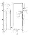
- the method according to the invention is used to transmit, from an aircraft 10 to an external load 12 constituted by a braked bomb (FIG. 1), programming data representing the time interval between the separation of the load, caused by the pilot, and the command to deploy a parachute.
- the load 12 is mounted under a pylon 14 comprising an ejector 16 to which the load is attached.
- Figure 2 shows a possible mounting of the transmitting source 32 carried by the aircraft and the sensor 34 of the receiver carried by the load.
- the source 32 constituted for example by a current type light-emitting diode, is mounted in the pylon 14 behind a window 36 flush with the underside of the pylon.
- the sensor 34 which will generally be a photodiode having a sensitivity range adapted to the wavelength of the source 32, is similarly mounted on the load, possibly behind a filter adapted to the emission wavelength of the source 32.
- a flexible sleeve 38 can be fixed to the pylon 14 in order to delimit a protected space around the path of transmission. If this transmission is by diffusion, and not in the form of a directed beam, it is not necessary that the source 32 and the sensor 34 are perfectly aligned. In this case, this makes it possible in particular to mount, on a given pylon 14, loads having different constitutions and on which the position of the sensor can vary, from one load to another, relative to a given reference (position of the transmitter on the pylon).
- a precision of 1 / 100th of a second on the value to be transmitted of the time interval between the release of the load and the opening of the parachute is largely sufficient.
- a data word of twelve useful bits, the least significant bit of which represents 10 ms, makes it possible to represent a delay of up to forty seconds, greater than all the values currently necessary in practice.
- the messages transmitted can comprise thirty-two bits so as to be directly compatible with the words provided for by existing aeronautical standards and have the format shown in Figure 3.
- the message has a header 20 of eight bits, a useful area 22 of twenty-one bits, composed of a word 24 of information of sixteen bits and a reserved part of five bits, two bits 28 of validity check and one bit of parity 30.
- a modulation frequency of 6.4 kHz for example which can be obtained without difficulty with low-cost infrared sources, such as light-emitting diodes or LEDs, is sufficient to transmit the thirty-two bits of the message. in 5 ms. However, it would be possible to use a source and a sensor that could operate at much higher frequencies if the data rate to be transmitted exceeded the possibilities offered by an LED.
- the load 12 is also provided with an emission source 60 and the pylon is then provided with a sensor 64, which makes it possible to transmit information from the load to the aircraft and thereby achieve a dialogue between the load and the carrier vehicle.
- the sources and the sensors will be identical, which requires working in alternation. But this condition is not in practice a problem for most applications: in the case, mentioned above, of thirty-two bit messages having a duration of 5 ms, it is possible to adopt a refresh rate of 50 Hz, reserving an interval of 5 ms between each transmission for the return transmission which follows it.
- the source and the sensor carried by the pylon 14 can be placed side by side, with an interval corresponding to that of the sensor and the source carried by the load.
- Flexible sleeves can be provided to isolate each path from the other.
- the message described above by way of example is transmitted from the carrier pylon to the load by air using an infrared type connection according to the wavelength specified in the example (0.83 ⁇ m).
- the receiver carried by the load comprises, from the sensor 34, a decoder 48 programmed so as to check the consistency of the message, in particular by using the control word and the parity bit, to decode it and to transmit the data obtained to a buffer memory 50 whose read access 52 is connected to the electronic circuits 72 for using the information, advantageously by means of an opto-electronic coupler of galvanic isolation 53.
- the message to be transmitted is transmitted by the source 60 on reception of an order supplied by a control logic 62 which maintains the interval of 5 ms required between the end of the reception of a message from the aircraft and the start message log.
- This report message is transmitted from the load to the carrier pylon by air using an infrared type link.
- the sensor 64 carried by the pylon is intended to receive the messages coming from the load; it attacks a decoder 66, similar in constitution to that of decoder 48, and provides a load identification word on a first output 68 and a validation word (in the event of coincidence between the information transmitted to the load and the feedback) on exit 70.
- the transceiver mounted in the pylon can be supplied from the general electrical circuit of the aircraft, generally at 28 Volts DC.
- a source of electrical power of low power sufficient to operate the data transmission circuits; this source, generally constituted by a low power battery, is implemented before takeoff of the aircraft, for example by removal of a safety pin placed on the load.
- the much greater energy required for implementation electronic circuits and the priming chain, for example to control the opening of a parachute, is supplied separately by a battery which is only put into Orservice when dropping, for example by a tearing strap or order a contact. Until then the priming chain remains inert.
- the pylon contains a microprocessor card 74 fulfilling the functions of frame generation and coding-decoding, connected by a modulator 76 to the transmission source 32 and by a demodulator 78 to the receiver 64.
- the card 74 is connected, by a coupler 77 and a connector 79, to the bus 80 of the carrier vehicle ensuring the connection with the on-board computer.
- the load for its part, contains a microprocessor card 82 connected respectively to the receiver 34 and to the transmitter 60 by a demodulator 84 and a modulator 86. It fulfills the functions of the members 50, 48, 54 and 62 of FIG. 4 It is connected by an opto-electronic coupler 53 to the electronic circuits 72 for implementing the load.
- the load includes an autonomous supply.
- This power supply includes a low power source 88, constituted for example by a lithium battery, which is connected to the circuits carried by the load before the start of the mission, for example by removal of an opening pin of a switch. 90.
- the power necessary for implementing the electronic circuits 72 and the activation chain is supplied by a high power source 94, brought into service when the load is separated.
- this battery can be controlled by a switch 92 which opens during the separation.
- the switch also makes it possible to provide a drop top to the microprocessor card 82 and then to cause, with the possible delay necessary for the source 72 to supply its operating voltage, the transfer of the data.
- the source 94 can in particular be a thermal battery, supplying a voltage greater than a minimum which is itself lower than the maximum voltage which the source 88 can supply.
- the microprocessor card 82 receives, controls, validates and stores the data coming from the carrier vehicle, and this almost permanently. Upon receipt of the drop signal, the card 82 transmits to circuits 72 the latest information received and validated, stored in the RAM of the microprocessor.
- FIG. 6 shows a possible arrangement of the components which have just been described. All of the electronic components carried by the pylon constitute a module 96 connected to the bus by the connector 78. The components carried by the load 12 can be grouped in a second module 98 carrying the receiver 34 and possibly the transmitter 60.
- the invention is susceptible of numerous variant embodiments.
- the principle of a unidirectional double link can be adopted.
- the transceiver mounted in the pylon can be provided to transmit, according to a determined repetition sequence, messages having different headers and each corresponding to a type dump.
- the load transceiver will include header recognition means, making it possible to take into account only the messages being sent to it. actually intended.
- the invention is capable of numerous applications and can be used on vehicles of very varied types. In all cases, the invention makes it possible to transmit the information with a space-saving device, capable of being housed in locations provided for the power supply connectors of many adapters; the device is very flexible and makes it possible to transmit very diverse parameters; the device does not require precise alignment of components when mounting the load. Finally, it allows without major difficulties to re-equip existing loads.
- the invention can be applied, as a priority, by way of nonlimiting examples, to droppable loads with a view to transmitting orders such as: choice of trajectory, opening of parachute (s), cocking of rockets , ejection of submunitions ...
- the invention can be applied to all types of missiles, on board an aircraft (air-to-air, air-to-ground missiles ...) or not (missiles ground-ground, ground-air, sea-sea etc ...) as well as torpedoes or even shells.
Landscapes
- Engineering & Computer Science (AREA)
- General Engineering & Computer Science (AREA)
- Optical Communication System (AREA)
- Stored Programmes (AREA)
Claims (10)
- Verfahren zur Übertragung von Programmierdaten von einem Trägerfahrzeug (10), wie zum Beispiel einem Luftfahrzeug, an eine externe oder integrierte Ladung (12), demgemäß die Daten durch Modulation einer optischen Strahlung von einem Sender, der auf dem Trägerfahrzeug vorgesehen ist, an einen Empfänger übertragen werden, der zu einer eigenständigen Vorrichtung gehört, die in der Ladung angeordnet ist und Schaltkreise zur Verarbeitung der Daten enthält, dadurch gekennzeichnet, daß man in wiederholter Weise Aktualisierungsdaten an eine Ladung überträgt, die in einen Schreib-Lese-Speicher in der Ladung gespeichert werden, wobei die zuletzt gespeicherten Daten erst nach Trennung von Ladung und Trägerfahrzeug aus dem Speicher an die Schaltkreise übermittelt werden.
- Verfahren nach Anspruch 1, dadurch gekennzeichnet, daß die Strahlung im infraroten Spektrum liegt.
- Verfahren nach Anspruch 1 oder 2, dadurch gekenn-zeichnet, daß die Daten in wiederholter Weise in Form von aufeinanderfolgenden Nachrichten übertragen werden.
- Verfahren nach Anspruch 3, dadurch gekennzeichnet, daß die Nachrichten, die an den gleichen Typ von Ladung übertragen werden, alle die gleiche Dauer haben und einen Kopfteil (20), ein oder mehrere Datenworte (22) und Bits (28) zur Fehlerkontrolle einschließt.
- Verfahren nach Anspruch 3, dadurch gekennzeichnet, daß die übertragenen Daten mehreren Typen von Ladungen entsprechen können, wobei jede Nachricht gleichermaßen eine Identifizierungsadresse umfaßt, die einem Typ von Ladung eigen ist, und wobei jede Ladung eine Vorrichtung umfaßt mit der die Informationsdaten, die für diese bestimmt sind, ausgewählt werden können.
- Verfahren nach Anspruch 4 oder 5, dadurch gekennzeichnet, daß Parameter zur Verifikation oder Programmierung von der Ladung zum Trägerfahrzeug in Antwort auf die Übertragung zur Ladung übertragen werden.
- Vorrichtung zur Programmierung einer externen Ladung von einem Trägerfahrzeug aus, die auf dem Trägerfahrzeug umfaßt: Vorrichtungen (40) zur Berechnung der Programmierdaten der Ladung und Vorrichtungen zur Erzeugung von Programmiernachrichten auf der Basis der Daten, die von den Vorrichtungen zur Berechnung (40) geliefert werden, und zur Modulation einer Strahlungsquelle (32) für Sendung an die Ladung über einen Zwischenraum hinweg zwischen der letzteren und dem Trägerfahrzeug; und die weiterhin auf der Ladung umfaßt: einen Sensor (34), der an die Quelle angepaßt ist, und einen Dekoder (48) zur Rekonstruktion der Daten, die in der empfangenen Nachricht enthalten sind, dadurch gekennzeichnet, daß die Erzeugungsvorrichtungen vorgesehen sind, um Aktualisierungsdaten in wiederholter Weise in einen sich in der Ladung befindlichen Schreib-Leser-Speicher zu leiten, der Dekoder (48) Programmierdaten von der Ladung an einen Zwischenspeicher überträgt und Vorrichtungen vorgesehen sind, um in Antwort auf die Trennung von Trägerfahrzeug und Ladung die Sendung der Daten an die Schaltkreise, die die Daten verarbeiten, auszulösen.
- Vorrichtung nach Anspruch 7, dadurch gekennzeichnet, daß die Ladung ebenso umfaßt: eine Strahlungsquelle (60) für Sendung über einen Zwischenraum zwischen Trägerfahrzeug und Ladung hinweg an einen Sensor (64), der auf dem die Ladung tragenden Fahrzeug montiert ist und Vorrichtungen (56, 62), um eine Modulationnachricht der Strahlungsquelle zu erzeugen, die eine Kopie der vom Dekoder (48) rekon-struierten Daten und ein oder mehrere Identifikationsworte der Ladung enthält.
- Vorrichtung nach Anspruch 8, dadurch gekennzeichnet, daß die beiden Quellen bei der gleichen Wellenlänge arbeiten, und daß die Erzeuger für einen alternierenden Betrieb vorgesehen sind.
- Vorrichtung nach Anspruch 7, 8 oder 9, dadurch gekennzeichnet, daß die Ladung eine elektrische Quelle von schwacher Leistung, die bestimmt ist, die Ubertragung der Daten sicherzustellen und eine Batterie trägt, die mehr Energie liefern kann, und die erst in Antwort auf die Abtrennung der Ladung in Betrieb genommen wird.
Applications Claiming Priority (2)
| Application Number | Priority Date | Filing Date | Title |
|---|---|---|---|
| FR8814497A FR2638922B1 (fr) | 1988-11-07 | 1988-11-07 | Procede et dispositif de programmation, par voie aerienne, d'une charge externe ou integree a partir d'un vehicule porteur |
| FR8814497 | 1988-11-07 |
Publications (2)
| Publication Number | Publication Date |
|---|---|
| EP0368738A1 EP0368738A1 (de) | 1990-05-16 |
| EP0368738B1 true EP0368738B1 (de) | 1993-06-09 |
Family
ID=9371627
Family Applications (1)
| Application Number | Title | Priority Date | Filing Date |
|---|---|---|---|
| EP19890403048 Expired - Lifetime EP0368738B1 (de) | 1988-11-07 | 1989-11-06 | Verfahren und Vorrichtung zur Programmierung einer äusseren oder integrierten Ladung mittels einer drahtlosen Verbindung in einem sie tragenden Fahrzeug |
Country Status (4)
| Country | Link |
|---|---|
| EP (1) | EP0368738B1 (de) |
| DE (1) | DE68907022T2 (de) |
| ES (1) | ES2041026T3 (de) |
| FR (1) | FR2638922B1 (de) |
Families Citing this family (7)
| Publication number | Priority date | Publication date | Assignee | Title |
|---|---|---|---|---|
| US5048771A (en) * | 1989-11-15 | 1991-09-17 | Hughes Aircraft Company | Method and apparatus for a reprogrammable program missile memory |
| FR2687260B1 (fr) * | 1992-02-12 | 1995-02-24 | Telecommunications Sa | Procede de transmission de donnees par faisceau optique entre un vehicule porteur et sa charge et dispositif pour la mise en óoeuvre du procede. |
| DE4234878C2 (de) * | 1992-10-16 | 1995-03-30 | Deutsche Aerospace | Verfahren zur autonomen Lagesteuerung von Lenkflugkörpern |
| US5681008A (en) * | 1996-09-26 | 1997-10-28 | Boeing North American, Inc. | Remote identification, location and signaling response system |
| US6057949A (en) * | 1997-08-07 | 2000-05-02 | The Boeing Company | Bi-directional infrared communications system |
| DE10152862A1 (de) * | 2001-10-25 | 2003-05-15 | Rheinmetall Landsysteme Gmbh | Verfahren zur Tempierung einer Munitionseinheit sowie tempierbare Munitionseinheit |
| US6823767B2 (en) | 2001-10-24 | 2004-11-30 | Rheinmetall Landsysteme Gmbh | Method for fuze-timing an ammunition unit, and fuze-timable ammunition unit |
Family Cites Families (5)
| Publication number | Priority date | Publication date | Assignee | Title |
|---|---|---|---|---|
| US3228337A (en) * | 1962-12-04 | 1966-01-11 | Rodney E Grantham | Radio frequency free communication system |
| US4091734A (en) * | 1977-02-22 | 1978-05-30 | The United States Of America As Represented By The Secretary Of The Navy | Aircraft to weapon fuze communication link |
| CA1233896A (en) * | 1983-04-11 | 1988-03-08 | Kenneth N. Jarrott | Programmable electronic delay fuse |
| DE3411439C1 (de) * | 1984-03-28 | 1985-09-19 | Messerschmitt-Bölkow-Blohm GmbH, 8012 Ottobrunn | Absetzverfahren für Lenkflugkörper |
| US4597345A (en) * | 1984-10-29 | 1986-07-01 | The United States Of America As Represented By The Secretary Of The Navy | Torpedo cableless umbilical |
-
1988
- 1988-11-07 FR FR8814497A patent/FR2638922B1/fr not_active Expired - Fee Related
-
1989
- 1989-11-06 EP EP19890403048 patent/EP0368738B1/de not_active Expired - Lifetime
- 1989-11-06 ES ES89403048T patent/ES2041026T3/es not_active Expired - Lifetime
- 1989-11-06 DE DE1989607022 patent/DE68907022T2/de not_active Expired - Fee Related
Also Published As
| Publication number | Publication date |
|---|---|
| ES2041026T3 (es) | 1993-11-01 |
| FR2638922A1 (fr) | 1990-05-11 |
| DE68907022D1 (de) | 1993-07-15 |
| FR2638922B1 (fr) | 1994-04-29 |
| EP0368738A1 (de) | 1990-05-16 |
| DE68907022T2 (de) | 1993-09-16 |
Similar Documents
| Publication | Publication Date | Title |
|---|---|---|
| EP0709254B1 (de) | Elektronisches Informationsübertragungssystem auf stromführenden Leitungen, insbesonders für ein Kraftfahrzeug | |
| US10812880B2 (en) | Data in motion storage system and method | |
| EP0368738B1 (de) | Verfahren und Vorrichtung zur Programmierung einer äusseren oder integrierten Ladung mittels einer drahtlosen Verbindung in einem sie tragenden Fahrzeug | |
| EP1745309B1 (de) | Flugzeug-antiraketen-schutzsystem | |
| EP2045565B1 (de) | Vorrichtung zur Fernsteuerung eines Vielanzeigers aus einem Angriffsmodul sowie ein Angriffsmodul und Vielanzeiger zur Umsetzung solcher Vorrichtung | |
| EP0628897B1 (de) | Gerät zur automatischen Flugzeugsteuerung | |
| EP0506567A1 (de) | Schnell wiederkonfigurienbare lichtwellenlänge Multiplexer | |
| FR2607346A1 (fr) | Agencement de groupes d'elements de circuit de traitement de signaux | |
| EP0628898B1 (de) | Gerät zur automatischen Flugzeugsteuerung | |
| EP0412016B1 (de) | Luftraumbeobachtungsvorrichtung für ein Unterseeboot | |
| EP3715770A1 (de) | System zum neutralisieren eines zielobjekts mithilfe einer drohne und eines flugkörpers | |
| EP1315319B1 (de) | Digitales Signalübertragungssystem für ein Raumfahrzeug | |
| FR2575285A1 (fr) | Codeur optique de reperage de position | |
| EP1045588A1 (de) | Vorrichtung zur Übertragung von digitalen Videobildern | |
| FR2726643A1 (fr) | Dispositif d'observation d'une zone de terrain | |
| EP0282394A1 (de) | Selektive Kugelschiesseinrichtung und -methode für Flugzeuge oder andere Apparate | |
| FR2733326A1 (fr) | Systeme pour determiner la position et l'angle de roulis d'un mobile | |
| EP3685528B1 (de) | Stealth-übertragung zwischen einer quelle an bord eines satelliten oder eines flugzeugs und einem entfernten empfänger | |
| EP1592159B1 (de) | Optisches Übertragungsnetz mit Baumstruktur | |
| EP0433161B1 (de) | Landungshilfssystem vom Typ MLS mit zentralen Mitteln zur Erzeugung von Mikrowellen | |
| EP0252821B1 (de) | Übertragungsverfahren und System für ein Initiierungskommando einer Einrichtung, die sich an Bord einer Maschine befindet | |
| EP4733200A1 (de) | Vorrichtung zur neutralisierung eines künstlichen satelliten und verfahren dafür | |
| FR2687260A1 (fr) | Procede de transmission de donnees par faisceau optique entre un vehicule porteur et sa charge et dispositif pour la mise en óoeuvre du procede. | |
| EP1317162A2 (de) | Rückgrat Schnittstelle, Endgerät Schnittstelle für Raumfahrzeug und Kommunikationsnetz mit solcher Schnittstellen | |
| WO2025061494A1 (fr) | Drone autoguide par dispositif optronique d'ecartometrie a double usage |
Legal Events
| Date | Code | Title | Description |
|---|---|---|---|
| PUAI | Public reference made under article 153(3) epc to a published international application that has entered the european phase |
Free format text: ORIGINAL CODE: 0009012 |
|
| AK | Designated contracting states |
Kind code of ref document: A1 Designated state(s): BE CH DE ES FR GB IT LI NL SE |
|
| 17P | Request for examination filed |
Effective date: 19901005 |
|
| 17Q | First examination report despatched |
Effective date: 19920326 |
|
| RAP1 | Party data changed (applicant data changed or rights of an application transferred) |
Owner name: MATRA DEFENSE |
|
| GRAA | (expected) grant |
Free format text: ORIGINAL CODE: 0009210 |
|
| AK | Designated contracting states |
Kind code of ref document: B1 Designated state(s): BE CH DE ES FR GB IT LI NL SE |
|
| PG25 | Lapsed in a contracting state [announced via postgrant information from national office to epo] |
Ref country code: IT Free format text: LAPSE BECAUSE OF FAILURE TO SUBMIT A TRANSLATION OF THE DESCRIPTION OR TO PAY THE FEE WITHIN THE PRE;WARNING: LAPSES OF ITALIAN PATENTS WITH EFFECTIVE DATE BEFORE 2007 MAY HAVE OCCURRED AT ANY TIME BEFORE 2007. THE CORRECT EFFECTIVE DATE MAY BE DIFFERENT FROM THE ONE RECORDED.SCRIBED TIME-LIMIT Effective date: 19930609 Ref country code: SE Effective date: 19930609 |
|
| GBT | Gb: translation of ep patent filed (gb section 77(6)(a)/1977) |
Effective date: 19930609 |
|
| REF | Corresponds to: |
Ref document number: 68907022 Country of ref document: DE Date of ref document: 19930715 |
|
| REG | Reference to a national code |
Ref country code: ES Ref legal event code: FG2A Ref document number: 2041026 Country of ref document: ES Kind code of ref document: T3 |
|
| PG25 | Lapsed in a contracting state [announced via postgrant information from national office to epo] |
Ref country code: CH Effective date: 19931130 Ref country code: LI Effective date: 19931130 |
|
| PLBE | No opposition filed within time limit |
Free format text: ORIGINAL CODE: 0009261 |
|
| STAA | Information on the status of an ep patent application or granted ep patent |
Free format text: STATUS: NO OPPOSITION FILED WITHIN TIME LIMIT |
|
| 26N | No opposition filed | ||
| REG | Reference to a national code |
Ref country code: CH Ref legal event code: PL |
|
| PGFP | Annual fee paid to national office [announced via postgrant information from national office to epo] |
Ref country code: NL Payment date: 19961024 Year of fee payment: 8 |
|
| PGFP | Annual fee paid to national office [announced via postgrant information from national office to epo] |
Ref country code: GB Payment date: 19961029 Year of fee payment: 8 |
|
| PGFP | Annual fee paid to national office [announced via postgrant information from national office to epo] |
Ref country code: ES Payment date: 19961108 Year of fee payment: 8 |
|
| PGFP | Annual fee paid to national office [announced via postgrant information from national office to epo] |
Ref country code: BE Payment date: 19961212 Year of fee payment: 8 |
|
| PG25 | Lapsed in a contracting state [announced via postgrant information from national office to epo] |
Ref country code: GB Free format text: LAPSE BECAUSE OF NON-PAYMENT OF DUE FEES Effective date: 19971106 |
|
| PG25 | Lapsed in a contracting state [announced via postgrant information from national office to epo] |
Ref country code: ES Free format text: LAPSE BECAUSE OF EXPIRATION OF PROTECTION Effective date: 19971107 |
|
| PG25 | Lapsed in a contracting state [announced via postgrant information from national office to epo] |
Ref country code: BE Free format text: LAPSE BECAUSE OF NON-PAYMENT OF DUE FEES Effective date: 19971130 |
|
| BERE | Be: lapsed |
Owner name: MATRA DEFENSE Effective date: 19971130 |
|
| PG25 | Lapsed in a contracting state [announced via postgrant information from national office to epo] |
Ref country code: NL Free format text: LAPSE BECAUSE OF NON-PAYMENT OF DUE FEES Effective date: 19980601 |
|
| GBPC | Gb: european patent ceased through non-payment of renewal fee |
Effective date: 19971106 |
|
| NLV4 | Nl: lapsed or anulled due to non-payment of the annual fee |
Effective date: 19980601 |
|
| PGFP | Annual fee paid to national office [announced via postgrant information from national office to epo] |
Ref country code: FR Payment date: 19981117 Year of fee payment: 10 |
|
| PGFP | Annual fee paid to national office [announced via postgrant information from national office to epo] |
Ref country code: DE Payment date: 19981119 Year of fee payment: 10 |
|
| PG25 | Lapsed in a contracting state [announced via postgrant information from national office to epo] |
Ref country code: FR Free format text: LAPSE BECAUSE OF NON-PAYMENT OF DUE FEES Effective date: 20000731 |
|
| PG25 | Lapsed in a contracting state [announced via postgrant information from national office to epo] |
Ref country code: DE Free format text: LAPSE BECAUSE OF NON-PAYMENT OF DUE FEES Effective date: 20000901 |
|
| REG | Reference to a national code |
Ref country code: FR Ref legal event code: ST |
|
| REG | Reference to a national code |
Ref country code: ES Ref legal event code: FD2A Effective date: 20010301 |