EP0368746A1 - Verfahren zum diskreten Austauschen von elektromagnetischen Signalen zwischen einem ersten und einem zweiten Sende-Empfangsgerät und System zum Ausführen des Verfahrens - Google Patents
Verfahren zum diskreten Austauschen von elektromagnetischen Signalen zwischen einem ersten und einem zweiten Sende-Empfangsgerät und System zum Ausführen des Verfahrens Download PDFInfo
- Publication number
- EP0368746A1 EP0368746A1 EP89403060A EP89403060A EP0368746A1 EP 0368746 A1 EP0368746 A1 EP 0368746A1 EP 89403060 A EP89403060 A EP 89403060A EP 89403060 A EP89403060 A EP 89403060A EP 0368746 A1 EP0368746 A1 EP 0368746A1
- Authority
- EP
- European Patent Office
- Prior art keywords
- station
- interrogation signal
- interrogation
- transmitting
- signal
- Prior art date
- Legal status (The legal status is an assumption and is not a legal conclusion. Google has not performed a legal analysis and makes no representation as to the accuracy of the status listed.)
- Granted
Links
Images

Classifications
-
- G—PHYSICS
- G01—MEASURING; TESTING
- G01S—RADIO DIRECTION-FINDING; RADIO NAVIGATION; DETERMINING DISTANCE OR VELOCITY BY USE OF RADIO WAVES; LOCATING OR PRESENCE-DETECTING BY USE OF THE REFLECTION OR RERADIATION OF RADIO WAVES; ANALOGOUS ARRANGEMENTS USING OTHER WAVES
- G01S13/00—Systems using the reflection or reradiation of radio waves, e.g. radar systems; Analogous systems using reflection or reradiation of waves whose nature or wavelength is irrelevant or unspecified
- G01S13/74—Systems using reradiation of radio waves, e.g. secondary radar systems; Analogous systems
- G01S13/76—Systems using reradiation of radio waves, e.g. secondary radar systems; Analogous systems wherein pulse-type signals are transmitted
- G01S13/765—Systems using reradiation of radio waves, e.g. secondary radar systems; Analogous systems wherein pulse-type signals are transmitted with exchange of information between interrogator and responder
-
- G—PHYSICS
- G01—MEASURING; TESTING
- G01S—RADIO DIRECTION-FINDING; RADIO NAVIGATION; DETERMINING DISTANCE OR VELOCITY BY USE OF RADIO WAVES; LOCATING OR PRESENCE-DETECTING BY USE OF THE REFLECTION OR RERADIATION OF RADIO WAVES; ANALOGOUS ARRANGEMENTS USING OTHER WAVES
- G01S13/00—Systems using the reflection or reradiation of radio waves, e.g. radar systems; Analogous systems using reflection or reradiation of waves whose nature or wavelength is irrelevant or unspecified
- G01S13/74—Systems using reradiation of radio waves, e.g. secondary radar systems; Analogous systems
- G01S13/76—Systems using reradiation of radio waves, e.g. secondary radar systems; Analogous systems wherein pulse-type signals are transmitted
- G01S13/78—Systems using reradiation of radio waves, e.g. secondary radar systems; Analogous systems wherein pulse-type signals are transmitted discriminating between different kinds of targets, e.g. IFF-radar, i.e. identification of friend or foe
- G01S13/781—Secondary Surveillance Radar [SSR] in general
- G01S13/782—Secondary Surveillance Radar [SSR] in general using multimoding or selective addressing
Definitions
- the present invention relates to a method for discreetly exchanging electromagnetic signals between a first and a second transceiver station, these signals possibly being signals for point-to-point communication, or possibly being friend-enemy identification signals.
- Discretion consists in preventing, as much as possible, an interception and possible jamming of signals by an enemy. Discretion is a quality often sought after in the exchange of signals for military use, because the interception of these signals allows their jamming or makes it possible to determine the position of the forces present, by means of direction finding.
- the object of the invention is to remedy the drawbacks of the known method consisting in using highly directive transmit antennas.
- the object of the invention is a method essentially consisting in indicating to the interrogated station the direction where the interrogator station is located, by means of coded data incorporated into each interrogation signal sent by the interrogator station. This coded data indicates the direction in which the transmission of the interrogating station is directed at the time when it sends this interrogation signal. The station interrogated deduces the direction in which it must send its response signal.
- a process is carried out for discreetly exchanging electromagnetic signals between a first and a second transceiver station, the second ignoring the direction in which the first is located, characterized in that it consists in: - transmit, by means of the first station, at least one interrogation signal directed in the direction of the second station, this interrogation signal comprising coded data indicating the direction in which it is transmitted; - receive, by means of the second station, this interrogation signal, and decode the coded data contained in this signal, to determine the direction in which the first station is located; - send, by means of the second station, a response signal directed only in the direction where the first station is located.
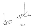
- Figure 1 shows the relative situation of two radio transceivers, 1 and 2.
- Station 1 having the initiative of exchanging radio signals, it is called interrogator station, while station 2 is called station interrogates.
- station 1 ignores the direction where station 2. is located. It interrogates in all directions to determine the friendly stations which surround it, or, in another example, station 1 seeks to establish a telephone call. with extension 2.
- Station 1 emits a series of interrogation signals respectively directed in a plurality of directions, contained in a horizontal plane and regularly distributed around a vertical axis. These directions make angles ⁇ 1, ..., ⁇ n respectively, with respect to a reference direction N which is for example the direction of geographic North.
- the station 1 includes a directive antenna whose beam 3 has a controllable direction. The number of directions depends on the directivity of the beam 3 of the transmitting antenna of station 1. If this transmitting antenna is very directive, station 1 transmits successively in a large number of directions in order to cover the entire horizontal plane , to be certain that station 2 receives at least one interrogation signal.
- Each interrogation signal comprises coded data characterizing a call and coded data indicating the direction in which the interrogation signal is transmitted. This direction is defined by the angle it makes with an absolute reference direction which is, for example, the direction N of geographic North.
- the beam 3 is directed exactly in the direction of the station 2 and then makes an angle ⁇ i with respect to the reference direction N.
- the station 2 can receive the interrogation signal sent by the station 1. It decodes the coded data indicating the direction ⁇ i in which the interrogation signal was sent and it deduces from it the direction ⁇ i + ⁇ where the station is located.
- the station 2 responds with a signal agreed in advance and allowing identify station 2. It emits this signal only in the direction making an angle ⁇ i + ⁇ with respect to the direction of geographic North.
- the response signal is transmitted by means of a directional antenna having a beam 4 whose direction is controllable.
- the transmitting antennas of station 1 and station 2 can be identical and can be made up of dipole arrays coupled to electrically controlled phase shifters, of conventional technique.
- This type of directional antenna makes it possible to instantly orient a beam of radio waves in a given direction.
- the realization of these antennas is easier in centimeter, millimeter waves, or even in the visible or infrared spectrum. These wave ranges allow in particular the creation of friend-enemy identification systems for land battlefields.
- the directivity of the transmitting antennas used determines the precision with which the value of the angle of the transmission direction relative to the North is coded.
- geographical The direction of the geographic North is given by a conventional navigation device. It suffices that this direction of geographic north is known with an accuracy at least as good as the accuracy of the direction of radiation of the transmitting antenna.
- the emission of the interrogation signals in a plurality of multiple directions is stopped as soon as the station 1 receives the response sent by the station 2.
- the movement beam 3 is then stopped. It keeps the direction ⁇ i compared to the direction of the geographic North.
- Station 2 initially ignoring the direction of 1, must be equipped with an omnidirectional reception antenna. But if the exchange of information is to be prolonged, he can advantageously, as soon as he knows the direction of 1, use the same directive antenna at reception as at transmission. It then benefits from the gain of this antenna and protects itself against any jammer which is not in the direction of 1.
- the interrogator station 1 it is also possible to obtain a discretion of the interrogator station 1, by avoiding the emission of a plurality of interrogation signals respectively in a plurality of directions around the interrogator station 1.
- the direction ⁇ i of station 2 it is possible to know the direction ⁇ i of station 2, by discrete means such as an optical sight.
- This optical viewfinder can be coupled to an angular position encoder, of conventional technique, to supply the value ⁇ i to a device for controlling the orientation of the beam 3.
- the station 1 knows the direction of the station 2 beforehand. He can then content himself with transmitting an interrogation signal in the direction ⁇ i where station 2 is located.
- a first tank can proceed to identify friend-enemy of a second tank by transmitting a radioelectric interrogation signal in a predetermined direction by means of an optical sight, therefore without using a plurality of interrogation signals emitted in all directions.
- FIG. 2 represents the block diagram of an exemplary embodiment of a system for implementing the method according to the invention in the case of an asymmetrical link.
- This system is for example a friend-enemy identification system in a radio frequency band, but it could be applied just as well to the establishment of radio-telephone communications.
- a completely analogous system can be implemented to operate in the visible or infrared spectrum.
- Station 1 is the only interrogator station. It comprises: a radio transmitter 11; a controllable directive antenna 12; a device 13 for controlling the antenna 12; a device 14 giving the direction of the geographic North; and a radio receiver 16.
- An output of the radio transmitter 11 is connected to an input of the antenna 12.
- An output of the device 13 is connected to an control input of the antenna 12 to control the direction of its radiation so to emit successively in directions ⁇ 1, ..., ⁇ n, covering the entire horizontal plane.
- the device 13 has an input connected to an output of the device 14 which can be, for example, a gyroscopic device.
- An input of the radio transmitter 11 is connected to the output of the device 13 to receive the value ⁇ i of the angle of the direction of emission at the instant considered, in order to code this value ⁇ i and to transmit it with data transmitted by the interrogator station 1.
- Station 2 is always an answering machine, never an interrogator. It comprises: a radio transmitter 21; a controllable directive antenna 22; a device 23 for controlling the antenna 22; a device 24 giving the direction of the North; an omnidirectional antenna 25; and a radio receiver 26.
- the omnidirectional antenna 25 has an output connected to an input of the radio receiver 26 to allow it to receive interrogation signals from all possible directions.
- the radio receiver 26 detects an interrogation signal, it decodes the data signifying it that it is called and the coded data indicating the direction ⁇ i in which the transmission was made.
- An output of the radio receiver 26 is connected to an input of the device 23 for controlling the antenna 22 to supply it with the value ⁇ i.
- Another input of the device 23 is connected to an output of the device 24 giving the direction of the North, for example, by means of a gyroscope.
- the device 23 determines the value ⁇ i + ⁇ of the angle between the direction of North and the direction which the emission of the answering station 2 must have in order to be able to reach the interrogating station 1. This angle value is provided by an output of the device 23 at a command input of the controllable directive antenna 22.
- the antenna 22 receives on another input a response signal R supplied by an output of the radio transmitter 21. This signal R is a coded signal identifying the station 2. It is received by the omnidirectional antenna 15 of station 1 and is decoded by its radio receiver 16.
- the station 2 can advantageously receive them by its directive antenna 22 since beyond the first message, the direction ⁇ i + ⁇ is known. Item 2 will thus benefit from the gain provided by the directive antenna 22, and will protect against any jammer not located in the direction of the station 1. For this, an input of the receiver station 26 receives the signals coming from the directive antenna 22.
- FIG. 3 represents the block diagram of an exemplary embodiment of a system for a symmetrical link, a station 1 ′ and a station 2 ′ which can be alternately interrogator and responder.
- the station 1 ' has the same elements as the station 1 described above, plus an omnidirectional antenna 15 connected to an additional input of the receiver 16 to receive the interrogation signals.
- the receiver 16 has an additional output, connected to an input of the device 13 to provide it with the angle value ⁇ j defining the direction from which an interrogation signal comes.
- Station 2 ′ has the same elements as station 2, but the radio transmitter 21 has an additional input, connected to an additional output of device 23, to receive each angle value ⁇ j defining a direction of emission when the station 2 is used as an interrogator station. Simultaneously, the value ⁇ j is supplied to the directive antenna 22 to orient its beam. Station 1 ′ responds with a signal R ′, supplied by the transmitter 11 and transmitted by the directive antenna 12, in the direction ⁇ j + ⁇ calculated by the device 13. The response signal R ′ is received by the directive antenna 22, in the direction ⁇ j.
- Radio directional antennas whose transmission direction is electrically controllable is very conventional.
- Orientable directional emission optics can also be produced by conventional techniques for the visible spectrum or the infrared spectrum.
- the invention is applicable in particular to military radio communications and friend-enemy identification.
Landscapes
- Engineering & Computer Science (AREA)
- Radar, Positioning & Navigation (AREA)
- Remote Sensing (AREA)
- Computer Networks & Wireless Communication (AREA)
- Physics & Mathematics (AREA)
- General Physics & Mathematics (AREA)
- Mobile Radio Communication Systems (AREA)
- Radar Systems Or Details Thereof (AREA)
Applications Claiming Priority (2)
| Application Number | Priority Date | Filing Date | Title |
|---|---|---|---|
| FR8814676 | 1988-11-10 | ||
| FR8814676A FR2638921B1 (fr) | 1988-11-10 | 1988-11-10 | Procede pour echanger discretement des signaux electromagnetiques entre un premier et un second poste emetteur-recepteur, et systeme pour la mise en oeuvre de ce procede |
Publications (2)
| Publication Number | Publication Date |
|---|---|
| EP0368746A1 true EP0368746A1 (de) | 1990-05-16 |
| EP0368746B1 EP0368746B1 (de) | 1993-12-29 |
Family
ID=9371751
Family Applications (1)
| Application Number | Title | Priority Date | Filing Date |
|---|---|---|---|
| EP19890403060 Expired - Lifetime EP0368746B1 (de) | 1988-11-10 | 1989-11-07 | Verfahren zum diskreten Austauschen von elektromagnetischen Signalen zwischen einem ersten und einem zweiten Sende-Empfangsgerät und System zum Ausführen des Verfahrens |
Country Status (4)
| Country | Link |
|---|---|
| EP (1) | EP0368746B1 (de) |
| CA (1) | CA2002465A1 (de) |
| DE (1) | DE68911870T2 (de) |
| FR (1) | FR2638921B1 (de) |
Cited By (2)
| Publication number | Priority date | Publication date | Assignee | Title |
|---|---|---|---|---|
| RU2763165C1 (ru) * | 2021-01-28 | 2021-12-28 | федеральное государственное казенное военное образовательное учреждение высшего образования "Краснодарское высшее военное орденов Жукова и Октябрьской Революции Краснознаменное училище имени генерала армии С.М. Штеменко" Министерства обороны Российской Федерации | Способ и система опознавания малогабаритных робототехнических средств |
| RU2769955C1 (ru) * | 2021-06-22 | 2022-04-11 | федеральное государственное автономное образовательное учреждение высшего образования "Северо-Кавказский федеральный университет" | Система опознавания «свой-чужой» на основе протокола аутентификации с нулевым разглашением |
Citations (4)
| Publication number | Priority date | Publication date | Assignee | Title |
|---|---|---|---|---|
| US3699570A (en) * | 1970-09-10 | 1972-10-17 | Us Air Force | Tacan ground station track and display system |
| FR2438275A1 (fr) * | 1978-10-06 | 1980-04-30 | Telecommunications Sa | Dispositif de reception et d'emission de signaux lumineux codes, et systeme iff comprenant ce dispositif |
| EP0127088A2 (de) * | 1983-05-26 | 1984-12-05 | Precitronic Gesellschaft für Feinmechanik und Electronic m.b.H | Verfahren zur Informationsübertragung |
| GB1605283A (en) * | 1973-10-01 | 1987-12-31 | Cossor Ltd A C | Vehicle identification |
-
1988
- 1988-11-10 FR FR8814676A patent/FR2638921B1/fr not_active Expired - Lifetime
-
1989
- 1989-11-07 EP EP19890403060 patent/EP0368746B1/de not_active Expired - Lifetime
- 1989-11-07 DE DE1989611870 patent/DE68911870T2/de not_active Expired - Fee Related
- 1989-11-08 CA CA 2002465 patent/CA2002465A1/fr not_active Abandoned
Patent Citations (4)
| Publication number | Priority date | Publication date | Assignee | Title |
|---|---|---|---|---|
| US3699570A (en) * | 1970-09-10 | 1972-10-17 | Us Air Force | Tacan ground station track and display system |
| GB1605283A (en) * | 1973-10-01 | 1987-12-31 | Cossor Ltd A C | Vehicle identification |
| FR2438275A1 (fr) * | 1978-10-06 | 1980-04-30 | Telecommunications Sa | Dispositif de reception et d'emission de signaux lumineux codes, et systeme iff comprenant ce dispositif |
| EP0127088A2 (de) * | 1983-05-26 | 1984-12-05 | Precitronic Gesellschaft für Feinmechanik und Electronic m.b.H | Verfahren zur Informationsübertragung |
Cited By (2)
| Publication number | Priority date | Publication date | Assignee | Title |
|---|---|---|---|---|
| RU2763165C1 (ru) * | 2021-01-28 | 2021-12-28 | федеральное государственное казенное военное образовательное учреждение высшего образования "Краснодарское высшее военное орденов Жукова и Октябрьской Революции Краснознаменное училище имени генерала армии С.М. Штеменко" Министерства обороны Российской Федерации | Способ и система опознавания малогабаритных робототехнических средств |
| RU2769955C1 (ru) * | 2021-06-22 | 2022-04-11 | федеральное государственное автономное образовательное учреждение высшего образования "Северо-Кавказский федеральный университет" | Система опознавания «свой-чужой» на основе протокола аутентификации с нулевым разглашением |
Also Published As
| Publication number | Publication date |
|---|---|
| DE68911870D1 (de) | 1994-02-10 |
| DE68911870T2 (de) | 1994-04-07 |
| FR2638921B1 (fr) | 1990-12-14 |
| CA2002465A1 (fr) | 1990-05-10 |
| EP0368746B1 (de) | 1993-12-29 |
| FR2638921A1 (fr) | 1990-05-11 |
Similar Documents
| Publication | Publication Date | Title |
|---|---|---|
| US20120068880A1 (en) | System and Method for Dual-Band Antenna Pointing, Acquisition, And Tracking | |
| CA2701538A1 (fr) | Systeme d'antenne embarque de poursuite de satellite avec controle de polarisation | |
| US5344099A (en) | Missile beamrider guidance using polarization-agile beams | |
| US20120099868A1 (en) | Hybrid communication apparatus for high-rate data transmission between moving and/or stationary platforms | |
| AU7340398A (en) | A terminal and antenna system for constellation of non- geostationary satellites | |
| US10320479B2 (en) | Intensity modulated direct detection broad optical-spectrum source communication | |
| FR2693329A1 (fr) | Procédé et système de pointage de deux antennes l'une en direction de l'autre. | |
| CN111130615B (zh) | Apt子系统和太空飞行器的通信系统 | |
| US10833405B2 (en) | Method of tracking steerable antennas on platforms to form an RF communication link | |
| EP0368746B1 (de) | Verfahren zum diskreten Austauschen von elektromagnetischen Signalen zwischen einem ersten und einem zweiten Sende-Empfangsgerät und System zum Ausführen des Verfahrens | |
| US9559427B2 (en) | Hybrid image gathering systems, satellite system, and related methods | |
| US12113608B2 (en) | Transmission of atmospheric ducted communication signals | |
| EP3378761B1 (de) | Antennensysteme mit flugzeugpropellern | |
| CN109120343B (zh) | 一种适用于卫星与水下动目标间蓝绿激光建链方法 | |
| EP1798809B1 (de) | Vorrichtung zum Ausstrahlen und/oder Empfangen von elektromagnetischen Wellen für aerodynamisch gesteuerte Luftfahrzeuge | |
| FR2986334A1 (fr) | Instrument radar satellitaire pour la surveillance maritime | |
| EP2446507A1 (de) | Verfahren zum helfen beim steuern einer antenne, dieses verfahren verwendende servosteuerantenne und mobiles endgerät mit einer solchen antenne | |
| US7382315B1 (en) | System for and method of improving beyond line-of-sight transmissions and receptions | |
| US12603704B2 (en) | Beaconless laser alignment with beamforming | |
| WO2026026281A1 (en) | Hybrid optical and radio frequency phased array antennas | |
| US11914071B2 (en) | Radar apparatus for detecting target object | |
| FR2833413A1 (fr) | Procede et dispositif de pointage d'antenne | |
| EP3521851B1 (de) | Vorrichtung und verfahren zum senden/empfangen von funksignalen | |
| EP0429349A1 (de) | Verfahren und Einrichtung zur Übertragung breitbandiger Signale mit Hilfe einer mobilen Ausrüstung | |
| Watson | Virtual Satcom, Long Range Broadband Digital Communications |
Legal Events
| Date | Code | Title | Description |
|---|---|---|---|
| PUAI | Public reference made under article 153(3) epc to a published international application that has entered the european phase |
Free format text: ORIGINAL CODE: 0009012 |
|
| AK | Designated contracting states |
Kind code of ref document: A1 Designated state(s): BE CH DE GB IT LI |
|
| 17P | Request for examination filed |
Effective date: 19901026 |
|
| 17Q | First examination report despatched |
Effective date: 19930430 |
|
| GRAA | (expected) grant |
Free format text: ORIGINAL CODE: 0009210 |
|
| AK | Designated contracting states |
Kind code of ref document: B1 Designated state(s): BE CH DE GB IT LI |
|
| ITF | It: translation for a ep patent filed | ||
| REF | Corresponds to: |
Ref document number: 68911870 Country of ref document: DE Date of ref document: 19940210 |
|
| GBT | Gb: translation of ep patent filed (gb section 77(6)(a)/1977) |
Effective date: 19940307 |
|
| PGFP | Annual fee paid to national office [announced via postgrant information from national office to epo] |
Ref country code: GB Payment date: 19941024 Year of fee payment: 6 |
|
| PGFP | Annual fee paid to national office [announced via postgrant information from national office to epo] |
Ref country code: DE Payment date: 19941025 Year of fee payment: 6 |
|
| PLBE | No opposition filed within time limit |
Free format text: ORIGINAL CODE: 0009261 |
|
| STAA | Information on the status of an ep patent application or granted ep patent |
Free format text: STATUS: NO OPPOSITION FILED WITHIN TIME LIMIT |
|
| PG25 | Lapsed in a contracting state [announced via postgrant information from national office to epo] |
Ref country code: LI Effective date: 19941130 Ref country code: CH Effective date: 19941130 Ref country code: BE Effective date: 19941130 |
|
| 26N | No opposition filed | ||
| BERE | Be: lapsed |
Owner name: LMT RADIO PROFESSIONNELLE Effective date: 19941130 |
|
| REG | Reference to a national code |
Ref country code: CH Ref legal event code: PL |
|
| PG25 | Lapsed in a contracting state [announced via postgrant information from national office to epo] |
Ref country code: GB Effective date: 19951107 |
|
| GBPC | Gb: european patent ceased through non-payment of renewal fee |
Effective date: 19951107 |
|
| PG25 | Lapsed in a contracting state [announced via postgrant information from national office to epo] |
Ref country code: DE Effective date: 19960801 |
|
| PG25 | Lapsed in a contracting state [announced via postgrant information from national office to epo] |
Ref country code: IT Free format text: LAPSE BECAUSE OF NON-PAYMENT OF DUE FEES;WARNING: LAPSES OF ITALIAN PATENTS WITH EFFECTIVE DATE BEFORE 2007 MAY HAVE OCCURRED AT ANY TIME BEFORE 2007. THE CORRECT EFFECTIVE DATE MAY BE DIFFERENT FROM THE ONE RECORDED. Effective date: 20051107 |