EP0368747A1 - Bewegungsabschätzungsverfahren eines Zieles in einer Bilderfolge und Einrichtung zur Durchführung dieses Verfahrens - Google Patents
Bewegungsabschätzungsverfahren eines Zieles in einer Bilderfolge und Einrichtung zur Durchführung dieses Verfahrens Download PDFInfo
- Publication number
- EP0368747A1 EP0368747A1 EP89403061A EP89403061A EP0368747A1 EP 0368747 A1 EP0368747 A1 EP 0368747A1 EP 89403061 A EP89403061 A EP 89403061A EP 89403061 A EP89403061 A EP 89403061A EP 0368747 A1 EP0368747 A1 EP 0368747A1
- Authority
- EP
- European Patent Office
- Prior art keywords
- image
- target
- matrix
- background
- vector
- Prior art date
- Legal status (The legal status is an assumption and is not a legal conclusion. Google has not performed a legal analysis and makes no representation as to the accuracy of the status listed.)
- Granted
Links
Images

Classifications
-
- H—ELECTRICITY
- H04—ELECTRIC COMMUNICATION TECHNIQUE
- H04N—PICTORIAL COMMUNICATION, e.g. TELEVISION
- H04N19/00—Methods or arrangements for coding, decoding, compressing or decompressing digital video signals
- H04N19/50—Methods or arrangements for coding, decoding, compressing or decompressing digital video signals using predictive coding
- H04N19/503—Methods or arrangements for coding, decoding, compressing or decompressing digital video signals using predictive coding involving temporal prediction
- H04N19/51—Motion estimation or motion compensation
- H04N19/527—Global motion vector estimation
-
- G—PHYSICS
- G06—COMPUTING OR CALCULATING; COUNTING
- G06T—IMAGE DATA PROCESSING OR GENERATION, IN GENERAL
- G06T7/00—Image analysis
- G06T7/20—Analysis of motion
- G06T7/262—Analysis of motion using transform domain methods, e.g. Fourier domain methods
Definitions
- the present invention relates to a method for estimating the movement of at least one target in a series of images, the movement of this target and the movement of the background of the images being comparable to translations.
- the estimation of the movement of a target allows the detection and the tracking of this target, despite the movement of the background of the images, due to the movement of the vehicle carrying the image sensor, and despite the movement of the target relative at the bottom of the images.
- the detection and the tracking of a target can be carried out according to two known methods: - either the target is modeled and attributes defining it are calculated. The detection then consists in looking in the image for an area defined by attributes little different from those of the target. - either the target is defined as being an area of moving pixels, between a reference image and the current image.
- the second method is implemented. First of all, it is necessary to readjust the background of the current image relative to the background of the reference image. It then consists in extracting the target by calculating the differences in luminance between the reference image and the current image after registration of its background. Pixels which have a difference in luminance greater than a fixed threshold value are considered to have a true movement, due to the presence of a moving target, while the pixels having a difference in luminance less than the threshold value are considered to have a movement due to noise.
- images are often very noisy, for example because they are provided by infrared image sensors. Noise makes it difficult to estimate the movement of the background, as well as detecting and estimating the movement of one or more targets.
- C.B. KUGLIN and D.C. HINES describe in: IEEE 1975, International Conference on Cybernetics and Society, San Francisco 1975, a method of estimating the translational motion of the background in a series of images, using phase correlation. It consists in sampling the current image and the reference image; calculating, for each of these two images, a matrix of coefficients transformed by the two-dimensional discrete Fourier transformation; calculating a so-called phase difference matrix, each coefficient of which is equal to the product of a coefficient of the first matrix, by the conjugate of a coefficient of the second matrix divided by the module of this product; calculating a matrix called inverse transformed matrix of the phase correlation matrix, by applying the inverse Fourier transformation to the phase correlation matrix; classify according to their module the coefficients of the inverse transformed matrix; estimate a translation vector of the background of the images, from the row of the row and the rank of the column where the coefficient with the largest modulus is located in the inverse transformed matrix of the phase correlation matrix.
- the object of the invention is to propose a method making it possible not only to estimate the movement of the background of the images, but also to detect and estimate the movement of one or more targets in these images.
- the object of the invention is a method consisting essentially in using the information provided by the module of the coefficients of the inverse transformed matrix of the phase correlation matrix, other than the one with the largest module.
- a method of estimating the movement of at least one target in a series of images, the movement of this target and the movement of the background of the images being comparable to translations is characterized in that it consists of: - sample each image then represent each sample by the value of its luminance; - calculate, for each image, a matrix of transformed coefficients, by the discrete Fourier transformation, in two dimensions; - calculate a so-called phase correlation matrix, each coefficient of which is equal to the product of a transformed coefficient of a first image, by the conjugate of a homologous transformed coefficient, of a second image, divided by the module of this product; - calculate a matrix, called inverse transformed matrix of the phase correlation matrix, by applying the inverse Fourier transformation, to the phase correlation matrix; - compare, with respect to a predetermined threshold value, the coefficients of the inverse transformed matrix of the phase correlation matrix and find the one having the largest module, this last coefficient corresponding to a translation of the background image, while the other coefficients having a modulus greater than
- the method according to the invention firstly consists in sampling each image of the sequence of images analyzed by a sensor, and in representing each sample by the value of its luminance. For example, each image is sampled in 256 x 256 pixels, using a conventional image sensor. The method then consists in calculating, for each image, a matrix of transformed coefficients, by the discrete Fourier transformation, in two dimensions.
- the values of the transformed coefficients F (u, v) are given by the following formula: where f (x, y) is the luminance value of the pixel of coordinates (x, y) in an oxy coordinate system centered for example in the upper left corner of the image, which is the starting point of the analysis ; where N1 and N2 are respectively the number of pixels per line, and the number of lines considered for the Fourier transformation.
- phase shift which is a function of the components of the translation vector.
- the matrix formed by the coefficients CP (u, v) is called the phase correlation matrix. It has 128x128 coefficients in this example.
- the method according to the invention consists in calculating the phase correlation matrix for the current image and the reference image, and then consists in calculating the inverse transformed matrix of the phase correlation matrix, by applying the Fourier transformation reverse, two-dimensional. Then it consists in calculating the modulus of each of the coefficients C (x, y) of this inverse transformed matrix; and to classify these coefficients according to the decreasing modules.
- FIG. 1 represents the graph of the modules of the coefficients C (x, y) in an example where the current image and the reference image comprises two targets in translation relative to the background.
- This graph then includes three peaks P1, P2, P3 corresponding to three coefficients whose modules are much greater than the modules of the other coefficients.
- the largest amplitude peak, P1 corresponds to the displacement of the background of the current image relative to the background of the reference image.
- the second peak in decreasing module order, P2 corresponds to a large target moving in relation to the background of the reference image.
- the third peak in decreasing module order, P3, is smaller than the peak P2 and corresponds to a target of apparent size smaller than the previous one, and moving relative to the background of the reference image.
- the other peaks are much smaller and correspond to noise.
- the coordinates (x, y) of each of these peaks P1, P2, P3, make it possible to estimate a translation vector.
- the coordinates of the peak P1 make it possible to estimate a translation vector of the background of the current image relative to the background of the reference image, this vector allowing a registration of the background of the current image.
- the coordinates of the peaks P2 and P3 make it possible to respectively estimate two translation vectors which characterize the movement of two distinct targets relative to the background of the reference image.
- the translation of the background between the reference image and the current image being known, these two translation vectors make it possible to determine an absolute speed vector for each target.
- the matrix of the modules of the coefficients C (x, y) comprises 128 ⁇ 128 discrete values, corresponding to the subsampling of 128 ⁇ 128 pixels. This number of values does not make it possible to obtain a very high precision in the determination of the components of the translation vectors.
- the method therefore preferably consists of interpolating to improve the estimation of the translation vectors.
- Figure 2 illustrates the interpolation method used to estimate the components of each translation vector.
- the method For each peak P, having a module L4, and coordinates (x1, y1), the method consists in considering the modules of the coefficients C (x, y) located in a window centered on the point of coordinate (x1, y1), this window having dimensions such that it contains nine coefficients. Taking into account the sub-sampling which takes into account only one point out of two horizontally and one point out of two vertically, the dimensions of the window are 5 ⁇ 5 pixels.
- the value modules L0, L3, L6 are located on the abscissa x0.
- the graph of the module of the coefficients C (x, y) is a two-dimensional surface which is known only by discrete points, spaced by a distance corresponding to a pixel.
- the peaks P found among the modules of the coefficients C (x, y) therefore do not correspond exactly with the true peaks M of the graph.
- the coordinates (xd, yd) of the true maximum M of the module graph are estimated by the following interpolation formulas:
- the method then consists in resetting the background of the current image with respect to the background of the reference image, as a function of the translation vector estimated for the background of the current image, and corresponding to the peak of module most large, P1. Since the components of the translation vector are generally non-integer values, the registration of the background of the current image is carried out by means of a known interpolation method, called bilinear interpolation method.
- Figure 3 illustrates this interpolation process.
- the pixel of the readjusted image is centered at point E whose coordinates are (xA + Dx, yA + Dy), Dx and Dy being between 0 and 1 pixel.
- Point E is located between 4 points A, B, C, D which are the pixel centers where the luminance value is known. These points have coordinates respectively (xA, yA), (xA + 1, yA), (xA, yA + 1), (xA + 1, yA + 1).
- the luminance value interpolated at point E is then given by the formula:
- the targets detected by peaks P2 and P3 are only possible targets; because noise generates false alarms. It is necessary to verify, by other means, that these possible targets are not noise. On the other hand, it remains to determine the position of these targets in the current image, in order to pursue them.
- the method then consists in calculating the values of the luminance differences between the current image readjusted and the reference image; all of these values being called "difference image".
- the non-zero differences in luminance are due either to a displacement of a target relative to the background of the current image; either noise which is very important in the case of an infrared image; or imperfections of the sensor resulting in an uneven average response from one line to another.
- the method consists in carrying out, before calculating the differences in luminance, a so-called line equalization operation.
- This equalization consists in subtracting from each luminance value of an image, the average value of the luminances of the line to which the pixel considered belongs. The average luminance value on each line is then zero.
- the method according to the invention then consists in carrying out a first discrimination of the targets by comparing the absolute value of each difference in luminance with respect to a fixed threshold value. Pixels with a luminance difference greater than the threshold value are considered to have true motion, while the others are considered to be fixed and affected by noise.
- the threshold value is set according to the tolerable false alarm rate.
- An additional step of the method consists in grouping the pixels which have a difference in luminance greater than the threshold value, in zones of connected pixels, each zone being identified by a number and being characterized by a state vector.
- This state vector has several components: - the number of pixels making up the area; - the coordinates of the barycenter of these pixels; - the mean absolute value of the luminance differences in the area; - the maximum coordinates of the pixels in the area, these coordinates making it possible to define a frame surrounding the possible target.
- the allocation of the pixels, as the difference image is scanned, leads to the creation of new zones, or to the extension of existing zones, or to the merging of an zone with another which appears to be related.
- Each of these operations on the zones results in an update of the components of the state vectors of the zones. For example, when a pixel having a difference in luminance greater than the threshold value is connected to two zones already encountered, it is allocated to a zone resulting from the fusion of these two zones. The state vector of the resulting area is determined based on the state vectors of the two areas which are merged.
- the allocation of pixels to areas can be done using different recursive methods. A known process is described in French patent application No. 2,599,205.
- a second step of discriminating targets can consist in declaring that an area is a target, and not noise, if the number of pixels constituting this area is greater than a second fixed threshold value. However, this discrimination should not prevent the detection of targets which are at the limit of visibility.
- a third target discrimination step can consist in estimating a speed vector for each of the moving pixel areas, by a known method, then in comparing the modulus of the speed vector thus estimated, with the modulus of the speed vector calculated from of the translation vector corresponding to each of the peaks detected in the inverse transformed matrix of the phase correlation matrix.
- the estimation of the speed vector of each zone can be carried out according to a known method, described in patent application GB 2,134,344.
- this method has the advantage of identifying the plurality of moving areas as being a single target, while a discrimination using only the comparison of the difference in luminance with respect to a threshold does not make it possible to know that this plurality of zones belongs to the same target, since the difference image shows nothing in the space between these different zones, since all the smallest luminance differences have been eliminated after comparison with the threshold value .
- a target is then validated if the distance it travels between a reference image and a current image is less than a maximum displacement calculated as a function of a speed value deduced from a detected peak, and as a function of the time separating the two images.
- This process can be improved by validating a target only if the temporal continuity is observed during a number of successive images, greater than a fixed value. The count of observations is reset to zero each time the target is not found in an image.
- the sequence of images analyzed by the sensor gives rise to the calculation of a sequence of inverse transformed matrices of the phase correlation matrix.
- the target peak is also found with a remarkable temporal continuity which also makes it possible to discriminate the peak of the targets compared to the parasitic peaks, by validating a target peak only if the temporal continuity of its coordinates is observed during a number of images greater than a fixed value.
- the method according to the invention can be implemented in real time, in particular if each image is subsampled to dimensions of 128 ⁇ 128 pixels, to make the calculations faster.
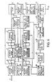
- FIG. 4 represents the block diagram of an exemplary embodiment of a device for the implementation of this method.
- This exemplary embodiment comprises: an input terminal 1 receiving a series of luminance values supplied by an image sensor, a sampler, and a line equalization device, not shown in the figure; 2,3,4 image memories for storing respectively a current image, an intermediate image, and a reference image; memories 5, 6 and 7 for respectively storing the transformed coefficients of the current image, of the intermediate image, and of the reference image, transformed by the discrete Fourier transformation, in two dimensions; switching devices 8,9,10,11; a device 12 for calculating two-dimensional discrete Fourier transformation; a transfer control device 13; an image memory 14 for storing the current readjusted image; an image memory 15 for storing a difference image; a subtractor 16; a device 17 for calculating the current image readjusted in translation; a device 18 for calculating a phase correlation matrix; a device 19 for calculating the inverse discrete Fourier transformation, two dimensions; a device 20 for searching
- the transfer control device 13 has: an output connected to a control input of the switching devices 8 and 10; an output connected to an input of control of switching devices 9 and 11; and outputs connected respectively to read and write control inputs, memories 2 to 7, and memories 14 and 15.
- the memories 2 and 5 are controlled parallel simultaneously.
- Memories 3 and 6 are controlled in parallel simultaneously.
- Memories 4 and 7 are controlled in parallel simultaneously.
- the input terminal 1 is connected to a data input from the memory 2.
- a data output from the memory 2 is connected to a first input of the device 17 to an input of the device 12, and to an input of the switching device 8.
- An output of the device 8 is connected to a data input of the memory 3.
- a data output of the memory 3 is connected to a data input of the memory 4 via the switching device 9.
- An output of data from memory 4 is connected to a first input of subtractor 16.
- An output of device 12 is connected to a data input of memory 5, to supply it with the values of the transformed coefficients of the current image.
- the device 12 calculates the discrete, two-dimensional Fourier transforms, luminance values of the current image, subsampled to 256 ⁇ 256 pixels. It implements a classical algorithm such as the FORMAN algorithm.
- a data output from memory 5 is connected to a data input from memory 6 via the switching device 10.
- a data output from memory 6 is connected to a data input from memory 7 by l through the switching device 11.
- the device 13 has an input connected to an output of the device 21 for receiving the value of the components of the translation vector of the background of the current image relative to the background of the reference image.
- the device 13 controls the switching device 9 and the memories 3 and 4 to transfer the luminance values of the intermediate image, stored in Memory 2, to memory 4; to constitute a new reference image.
- the device 13 controls the switching device 11 and the memories 6 and 7 to transfer the transformed coefficients of the intermediate image, stored in the memory 6, to the memory 7; so that they constitute the transformed coefficients of a new reference image.
- the device 13 controls the switching device 8 and memories 2 and 3 for transferring the luminance values of the current image, stored in memory 2, to memory 3; to form the luminance values of a new intermediate image. Simultaneously the device 13 controls the switching device 10 and the memories 5 and 6 to transfer the transformed coefficients corresponding to the current image, stored in the memory 5, to the memory 6; to constitute the transformed coefficients of an intermediate image.
- the device 13 does not make any transfer to memories 3 and 4, nor to memories 6 and 7. On the other hand, it continues to ensure the storage of the luminance values in the memory 2 in order to renew the current image; and storing, in memory 5, the transformed coefficients corresponding to each new current image.
- the computing device 18 has a first input connected to the data output of the memory 5; a second input connected to the data output of memory 7; and an output connected to an input of the computing device 19. An output of the latter is connected to an input of the device 20.
- the device 21 has: an input connected to an output of the device 20; a first output connected to a first input of the device 25, and a second output connected to an input of the device 13, to a second input of the device 17, and to a second input of the device 25.
- An output of the device 17 is connected to a data input of the memory 14.
- a data output from memory 14 is connected to a second input from subtractor 16.
- a read-write command input from memory 14 is connected to an output of device 13.
- the memory 15 has: a data input connected to an output of the subtractor 16; a control input connected to an output of the device 13; and an output connected to an input of the device 22.
- the device 23 has: a first input connected to an output of the device 22; a second input connected to an output of the device 25; and an output connected to the output terminal 24.
- the calculation device 18 calculates each coefficient of the phase correlation matrix in accordance with the formula (4) mentioned above.
- the device 19 calculates the discrete, two-dimensional inverse Fourier transform of the phase correlation matrix according to a conventional algorithm such as the Forman algorithm.
- the calculation device 20 calculates the modulus of each of the coefficients of the inverse transformation matrix of the phase correlation matrix; compares it to a threshold value which is fixed above the noise level so as to detect the coefficients corresponding to the translation of a target; and searches, among these coefficients, for the one with the largest module. This latter corresponds to the translation of the background of the current image with respect to the reference image.
- the calculation device 21 determines by an interpolation, in accordance with formula (5), the precise coordinates of the correlation peaks. These coordinates respectively constitute the components of a translation vector for the background image and a translation vector for each of the targets.
- the second output of the device 21 supplies the components of a background translation vector, on the one hand to the transfer control device 13, and, on the other hand, to the calculation device 17, for calculating the luminance values of the current image readjusted in translation.
- the device 17 calculates these luminance values in accordance with the formula (6), as a function of the luminance values of the current image read in the memory 2 under the control of the device 13.
- the luminance values of the current image readjusted are stored in memory 14, under the control of device 13.
- the second output of device 21 supplies the components of the translation vector from the bottom to the second input of device 25, while the first output of device 21 supplies the components translation vectors of the targets at the first input of the device 25. These components are defined with respect to a reference linked to the reference image.
- the calculation device 25 calculates the difference between each translation vector of a target and the translation vector of the image background, in order to obtain a translation vector defined in an absolute coordinate system. Then it calculates a speed vector for each target by dividing its translation vector by the duration separating the current image and the reference image.
- the subtractor 16 calculates the absolute values of the luminance differences between the readjusted current image and the reference image. Then these difference values are stored in the difference image memory, 15, under the control of the device 13.
- the device 22 for characterizing the moving areas compares the luminance difference values with respect to a predetermined threshold value. Each pixel for which the absolute value of the difference in luminance is greater than the threshold value is considered to be in true motion. The other pixels are either fixed or affected by noise.
- the device 22 assigns each moving pixel to an area made up of pixels that are moving and related. Each zone which has a number of pixels greater than a fixed threshold value, is capable of representing a target.
- the device 22 calculates a speed vector from the translation of the barycenter of this zone, from a first to a second difference image, the first difference image being a difference image calculated previously for a previous reference image and a previous current image, this first difference image being kept in memory in the device 22.
- the second difference image is constituted by the difference image stored in the memory 15.
- the device 22 provides the device 23 for validating the zones, on the one hand, a zone number making it possible to find the characteristics of this zone in a state vector memory inside the device 22; and, on the other hand, it provides it with the components of a speed vector, estimated for this area from the translation of this area from the first to the second difference image.
- the device 23 also receives, on its second input, the components of the target speed vectors, calculated by the device 25.
- the device 23 searches for the coincidence between the module of the speed vector of each zone and each of the modules of the speed vectors of target. For this, it compares respectively the modulus of the velocity vector of an area with the modulus of the velocity vector of each target, while having a predetermined tolerance margin.
- the device 23 detects a coincidence, it concludes that the zone considered belongs to the target having the speed considered. It provides the output terminal 24 with information consisting of the number of the validated area, or the numbers of the validated areas, with the components of the speed vector corresponding to this area, or to these areas.
- This number can be used, in another image processing device, to sort in the current image the areas which belong to a given target, and surround them with a frame, in order to view them on a screen, and to eliminate areas which do not belong to any target and which are probably due to noise.
- the device 22 for characterizing the moving areas can be produced in accordance with the teaching of the patent application GB No. 2 134 344.
- the Fourier transformation calculation devices, 12 and 19 can be specialized integrated circuits, available commercially, such as that marketed by ZORAN, of the VFP325 type.
- the other memory devices or calculation devices are of sufficiently conventional embodiment to be within the reach of those skilled in the art.
- the invention is applicable in particular to multi-target detection in infrared, visible, or radar images, when the displacements are comparable to translations.
Landscapes
- Engineering & Computer Science (AREA)
- Physics & Mathematics (AREA)
- Multimedia (AREA)
- Mathematical Physics (AREA)
- Computer Vision & Pattern Recognition (AREA)
- General Physics & Mathematics (AREA)
- Theoretical Computer Science (AREA)
- Signal Processing (AREA)
- Image Analysis (AREA)
Applications Claiming Priority (2)
| Application Number | Priority Date | Filing Date | Title |
|---|---|---|---|
| FR8814677 | 1988-11-10 | ||
| FR888814677A FR2638874B1 (fr) | 1988-11-10 | 1988-11-10 | Procede d'estimation du mouvement d'au moins une cible dans une suite d'images, et dispositif pour la mise en oeuvre de ce procede |
Publications (2)
| Publication Number | Publication Date |
|---|---|
| EP0368747A1 true EP0368747A1 (de) | 1990-05-16 |
| EP0368747B1 EP0368747B1 (de) | 1995-07-19 |
Family
ID=9371752
Family Applications (1)
| Application Number | Title | Priority Date | Filing Date |
|---|---|---|---|
| EP89403061A Expired - Lifetime EP0368747B1 (de) | 1988-11-10 | 1989-11-07 | Bewegungsabschätzungsverfahren eines Zieles in einer Bilderfolge und Einrichtung zur Durchführung dieses Verfahrens |
Country Status (6)
| Country | Link |
|---|---|
| US (1) | US5063524A (de) |
| EP (1) | EP0368747B1 (de) |
| JP (1) | JPH02181882A (de) |
| DE (1) | DE68923535T2 (de) |
| DK (1) | DK551589A (de) |
| FR (1) | FR2638874B1 (de) |
Cited By (4)
| Publication number | Priority date | Publication date | Assignee | Title |
|---|---|---|---|---|
| EP0627696A2 (de) | 1993-06-03 | 1994-12-07 | Matsushita Electric Industrial Co., Ltd. | Bildbewegungsvektornachweisgerät |
| EP0840255A3 (de) * | 1996-10-31 | 1999-09-01 | Yamatake Corporation | Vorrichtung zum Messen der Bewegungsrichtung und Verfolgungsgerät |
| DE19860038C1 (de) * | 1998-12-23 | 2000-06-29 | Siemens Ag | Verfahren zur Bewegungskorrektur bei Serien von Bildern eines starren Körpers |
| CN112529872A (zh) * | 2020-12-11 | 2021-03-19 | 昆山丘钛光电科技有限公司 | 一种摄像头模组的检测方法及装置 |
Families Citing this family (29)
| Publication number | Priority date | Publication date | Assignee | Title |
|---|---|---|---|---|
| US10361802B1 (en) | 1999-02-01 | 2019-07-23 | Blanding Hovenweep, Llc | Adaptive pattern recognition based control system and method |
| US8352400B2 (en) | 1991-12-23 | 2013-01-08 | Hoffberg Steven M | Adaptive pattern recognition based controller apparatus and method and human-factored interface therefore |
| JP3093409B2 (ja) * | 1992-01-10 | 2000-10-03 | 富士通株式会社 | 3次元計測装置 |
| GB9204117D0 (en) * | 1992-02-26 | 1992-04-08 | British Broadcasting Corp | Video image processing |
| FR2688369B1 (fr) | 1992-03-03 | 1996-02-09 | Thomson Csf | Procede de codage d'images a tres bas debit et dispositif de codage-decodage mettant en óoeuvre ce procede. |
| US5588067A (en) * | 1993-02-19 | 1996-12-24 | Peterson; Fred M. | Motion detection and image acquisition apparatus and method of detecting the motion of and acquiring an image of an object |
| US6122405A (en) * | 1993-08-27 | 2000-09-19 | Martin Marietta Corporation | Adaptive filter selection for optimal feature extraction |
| US5467374A (en) * | 1993-10-29 | 1995-11-14 | General Electric Company | Low complexity adaptive equalizer for U.S. digital cellular radio receivers |
| JPH07154795A (ja) * | 1993-12-01 | 1995-06-16 | Canon Inc | 動画像符号化装置 |
| WO1997023844A1 (en) * | 1995-12-21 | 1997-07-03 | Philips Electronics N.V. | Directional adaptive noise reduction |
| US6181747B1 (en) | 1996-02-01 | 2001-01-30 | Hughes Electronics Corporation | Methods and systems for high compression rate encoding and decoding of quasi-stable objects in video and film |
| US5940129A (en) * | 1996-12-06 | 1999-08-17 | Hughes Electronics Corporation | Methods and systems for super compression of prior known objects in video and film |
| US6008865A (en) * | 1997-02-14 | 1999-12-28 | Eastman Kodak Company | Segmentation-based method for motion-compensated frame interpolation |
| DE19751004A1 (de) * | 1997-11-18 | 1999-05-20 | Daimler Chrysler Ag | Verfahren zur Verarbeitung von Radarsignalen |
| US7966078B2 (en) | 1999-02-01 | 2011-06-21 | Steven Hoffberg | Network media appliance system and method |
| US6266452B1 (en) * | 1999-03-18 | 2001-07-24 | Nec Research Institute, Inc. | Image registration method |
| GB2356699A (en) * | 1999-11-23 | 2001-05-30 | Robotic Technology Systems Plc | Providing information of moving objects |
| US7061524B2 (en) * | 2001-11-13 | 2006-06-13 | The Board Of Trustees Of The Leland Stanford Junior University | Motion/saturation detection system and method for synthesizing high dynamic range motion blur free images from multiple captures |
| US6650273B1 (en) * | 2002-05-06 | 2003-11-18 | Lockheed Martin Corporation | Change subtraction of synthetic aperture radar data |
| JP2005539255A (ja) * | 2002-09-12 | 2005-12-22 | エヌライン、コーパレイシャン | 複合画像を捕捉し、かつ、処理するためのシステムおよび方法複合画像を捕捉し、かつ、処理するためのシステムおよび方法 |
| US7433494B2 (en) * | 2002-09-19 | 2008-10-07 | Denso Corporation | Moving body detecting apparatus |
| US20040161153A1 (en) * | 2003-02-18 | 2004-08-19 | Michael Lindenbaum | Context-based detection of structured defects in an image |
| JP4530742B2 (ja) * | 2004-07-01 | 2010-08-25 | Hoya株式会社 | モニタ制御装置 |
| US7609858B2 (en) * | 2004-08-31 | 2009-10-27 | Hewlett-Packard Development Company, L.P. | Displacement measurements using phase changes |
| FR2886020B1 (fr) * | 2005-05-19 | 2007-10-19 | Eurocopter France | Systeme d'estimation de la vitesse d'un aeronef et son application a la detection d'obstacles |
| CN102645970B (zh) * | 2011-02-22 | 2015-10-28 | 鸿富锦精密工业(深圳)有限公司 | 移动向量触发控制方法及使用其的电子装置 |
| US9274219B2 (en) * | 2011-07-07 | 2016-03-01 | Brian M. Lamb | Apparatus and method for short dwell inverse synthetic aperture radar (ISAR) imaging of turning moving vehicles |
| US10989793B2 (en) | 2017-12-01 | 2021-04-27 | Electromagnetic Systems, Inc. | Adaptive correction of radar channel-to-channel time-dependent errors |
| CN111434308A (zh) * | 2019-01-11 | 2020-07-21 | 西门子(深圳)磁共振有限公司 | 一种医学成像设备的病人监控方法及装置 |
Citations (2)
| Publication number | Priority date | Publication date | Assignee | Title |
|---|---|---|---|---|
| GB2187059A (en) * | 1986-02-20 | 1987-08-26 | British Broadcasting Corp | Motion detector for video signal prediction systems |
| WO1987005769A1 (en) * | 1986-03-19 | 1987-09-24 | British Broadcasting Corporation | Tv picture motion measurement |
Family Cites Families (8)
| Publication number | Priority date | Publication date | Assignee | Title |
|---|---|---|---|---|
| US4410798A (en) * | 1981-06-10 | 1983-10-18 | Itek Corporation | Incremental optical encoder system with addressable index |
| US4482970A (en) * | 1981-11-06 | 1984-11-13 | Grumman Aerospace Corporation | Boolean filtering method and apparatus |
| US4490851A (en) * | 1982-04-16 | 1984-12-25 | The United States Of America As Represented By The Secretary Of The Army | Two-dimensional image data reducer and classifier |
| US4845610A (en) * | 1984-07-13 | 1989-07-04 | Ford Aerospace & Communications Corporation | Target recognition using string-to-string matching |
| JPH0621801B2 (ja) * | 1985-07-03 | 1994-03-23 | キヤノン株式会社 | ロ−タリ−エンコ−ダ− |
| JPS6212814A (ja) * | 1985-07-10 | 1987-01-21 | Canon Inc | ロ−タリ−エンコ−ダ− |
| US4811254A (en) * | 1985-12-17 | 1989-03-07 | Nippon Gakki Seizo Kabushiki Kaisha | Displacement detector for an encoder |
| GB2199205A (en) * | 1986-12-23 | 1988-06-29 | Philips Electronic Associated | Angle digitiser |
-
1988
- 1988-11-10 FR FR888814677A patent/FR2638874B1/fr not_active Expired - Fee Related
-
1989
- 1989-11-06 DK DK551589A patent/DK551589A/da not_active Application Discontinuation
- 1989-11-07 EP EP89403061A patent/EP0368747B1/de not_active Expired - Lifetime
- 1989-11-07 DE DE68923535T patent/DE68923535T2/de not_active Expired - Fee Related
- 1989-11-09 US US07/433,790 patent/US5063524A/en not_active Expired - Fee Related
- 1989-11-10 JP JP1291397A patent/JPH02181882A/ja active Pending
Patent Citations (2)
| Publication number | Priority date | Publication date | Assignee | Title |
|---|---|---|---|---|
| GB2187059A (en) * | 1986-02-20 | 1987-08-26 | British Broadcasting Corp | Motion detector for video signal prediction systems |
| WO1987005769A1 (en) * | 1986-03-19 | 1987-09-24 | British Broadcasting Corporation | Tv picture motion measurement |
Cited By (6)
| Publication number | Priority date | Publication date | Assignee | Title |
|---|---|---|---|---|
| EP0627696A2 (de) | 1993-06-03 | 1994-12-07 | Matsushita Electric Industrial Co., Ltd. | Bildbewegungsvektornachweisgerät |
| EP0627696A3 (de) * | 1993-06-03 | 1996-04-17 | Matsushita Electric Industrial Co Ltd | Bildbewegungsvektornachweisgerät. |
| EP0840255A3 (de) * | 1996-10-31 | 1999-09-01 | Yamatake Corporation | Vorrichtung zum Messen der Bewegungsrichtung und Verfolgungsgerät |
| US6067367A (en) * | 1996-10-31 | 2000-05-23 | Yamatake-Honeywell Co., Ltd. | Moving direction measuring device and tracking apparatus |
| DE19860038C1 (de) * | 1998-12-23 | 2000-06-29 | Siemens Ag | Verfahren zur Bewegungskorrektur bei Serien von Bildern eines starren Körpers |
| CN112529872A (zh) * | 2020-12-11 | 2021-03-19 | 昆山丘钛光电科技有限公司 | 一种摄像头模组的检测方法及装置 |
Also Published As
| Publication number | Publication date |
|---|---|
| EP0368747B1 (de) | 1995-07-19 |
| JPH02181882A (ja) | 1990-07-16 |
| US5063524A (en) | 1991-11-05 |
| DE68923535D1 (de) | 1995-08-24 |
| DK551589D0 (da) | 1989-11-06 |
| FR2638874A1 (fr) | 1990-05-11 |
| DE68923535T2 (de) | 1996-01-04 |
| FR2638874B1 (fr) | 1994-07-01 |
| DK551589A (da) | 1990-05-11 |
Similar Documents
| Publication | Publication Date | Title |
|---|---|---|
| EP0368747B1 (de) | Bewegungsabschätzungsverfahren eines Zieles in einer Bilderfolge und Einrichtung zur Durchführung dieses Verfahrens | |
| EP1072014B1 (de) | Gesichtserkennung aus videobildern | |
| FR2947657A1 (fr) | Procede de detection d’un obstacle pour vehicule automobile | |
| US11069073B2 (en) | On-shelf commodity detection method and system | |
| CN115049731B (zh) | 一种基于双目摄像头的视觉建图和定位方法 | |
| FR2947656A1 (fr) | Procede de detection d'un obstacle pour vehicule automobile | |
| FR3081591A1 (fr) | Procede de traitement d'un flux d'images video | |
| EP3271869A1 (de) | Verfahren zur verarbeitung eines asynchronen signals | |
| EP0588815B1 (de) | Verfahren und vorrichtung zur auswertung von strassenbildsequenzen für die erkennung von hindernissen | |
| FR3093817A1 (fr) | Systeme de traitement radar et procede de debruitage associe | |
| EP3836014A1 (de) | Verfahren zur verfolgung eines elements, eines zugehörigen elektronischen geräts und eines computerprogrammprodukts | |
| EP3384462B1 (de) | Verfahren zur charakterisierung einer szene durch berechnung der 3d-orientierung | |
| Harisankar et al. | Unsupervised depth estimation from monocular images for autonomous vehicles | |
| Caefer et al. | Point target detection in consecutive frame staring IR imagery with evolving cloud clutter | |
| EP1580684A1 (de) | Gesichtserkennung aus Videobildern | |
| Fehr et al. | Reshaping our model of the world over time | |
| EP1646967A1 (de) | Verfahren zur messung der proxymität zweier konturen und system zur automatischen identifikation von zielen | |
| FR2680931A1 (fr) | Procede de detection et de suivi d'objets en mouvement par analyse de sequences d'images. | |
| CN112950709A (zh) | 一种位姿预测方法、位姿预测装置及机器人 | |
| JP4124861B2 (ja) | 移動量検出装置及びその方法 | |
| CN114998162B (zh) | 运动物体检测方法、装置、终端设备及存储介质 | |
| EP4439478A1 (de) | Verfahren zur verfolgung mehrerer objekte | |
| Stock et al. | Subpixel corner detection for tracking applications using cmos camera technology | |
| EP0550101A1 (de) | Verfahren zur Bildortungszurückstellung | |
| EP0219435B1 (de) | Bildkonturdetektionsverfahren und lokale Bewertung ihrer Parameter in einem Raum mit mindestens drei Dimensionen und Vorrichtung zum Durchführen dieses Verfahrens |
Legal Events
| Date | Code | Title | Description |
|---|---|---|---|
| PUAI | Public reference made under article 153(3) epc to a published international application that has entered the european phase |
Free format text: ORIGINAL CODE: 0009012 |
|
| AK | Designated contracting states |
Kind code of ref document: A1 Designated state(s): CH DE GB IT LI NL SE |
|
| 17P | Request for examination filed |
Effective date: 19901026 |
|
| 17Q | First examination report despatched |
Effective date: 19930601 |
|
| RAP1 | Party data changed (applicant data changed or rights of an application transferred) |
Owner name: THOMSON-CSF |
|
| GRAA | (expected) grant |
Free format text: ORIGINAL CODE: 0009210 |
|
| AK | Designated contracting states |
Kind code of ref document: B1 Designated state(s): CH DE GB IT LI NL SE |
|
| REF | Corresponds to: |
Ref document number: 68923535 Country of ref document: DE Date of ref document: 19950824 |
|
| ITF | It: translation for a ep patent filed | ||
| GBT | Gb: translation of ep patent filed (gb section 77(6)(a)/1977) |
Effective date: 19950922 |
|
| PLBE | No opposition filed within time limit |
Free format text: ORIGINAL CODE: 0009261 |
|
| STAA | Information on the status of an ep patent application or granted ep patent |
Free format text: STATUS: NO OPPOSITION FILED WITHIN TIME LIMIT |
|
| 26N | No opposition filed | ||
| PGFP | Annual fee paid to national office [announced via postgrant information from national office to epo] |
Ref country code: NL Payment date: 19961014 Year of fee payment: 8 Ref country code: CH Payment date: 19961014 Year of fee payment: 8 |
|
| PGFP | Annual fee paid to national office [announced via postgrant information from national office to epo] |
Ref country code: DE Payment date: 19961019 Year of fee payment: 8 |
|
| PGFP | Annual fee paid to national office [announced via postgrant information from national office to epo] |
Ref country code: SE Payment date: 19961021 Year of fee payment: 8 Ref country code: GB Payment date: 19961021 Year of fee payment: 8 |
|
| PG25 | Lapsed in a contracting state [announced via postgrant information from national office to epo] |
Ref country code: GB Free format text: LAPSE BECAUSE OF NON-PAYMENT OF DUE FEES Effective date: 19971107 |
|
| PG25 | Lapsed in a contracting state [announced via postgrant information from national office to epo] |
Ref country code: SE Free format text: LAPSE BECAUSE OF NON-PAYMENT OF DUE FEES Effective date: 19971108 |
|
| PG25 | Lapsed in a contracting state [announced via postgrant information from national office to epo] |
Ref country code: LI Free format text: LAPSE BECAUSE OF NON-PAYMENT OF DUE FEES Effective date: 19971130 Ref country code: CH Free format text: LAPSE BECAUSE OF NON-PAYMENT OF DUE FEES Effective date: 19971130 |
|
| PG25 | Lapsed in a contracting state [announced via postgrant information from national office to epo] |
Ref country code: NL Free format text: LAPSE BECAUSE OF NON-PAYMENT OF DUE FEES Effective date: 19980601 |
|
| GBPC | Gb: european patent ceased through non-payment of renewal fee |
Effective date: 19971107 |
|
| REG | Reference to a national code |
Ref country code: CH Ref legal event code: PL |
|
| PG25 | Lapsed in a contracting state [announced via postgrant information from national office to epo] |
Ref country code: DE Free format text: LAPSE BECAUSE OF NON-PAYMENT OF DUE FEES Effective date: 19980801 |
|
| EUG | Se: european patent has lapsed |
Ref document number: 89403061.8 |
|
| NLV4 | Nl: lapsed or anulled due to non-payment of the annual fee |
Effective date: 19980601 |
|
| PG25 | Lapsed in a contracting state [announced via postgrant information from national office to epo] |
Ref country code: IT Free format text: LAPSE BECAUSE OF NON-PAYMENT OF DUE FEES;WARNING: LAPSES OF ITALIAN PATENTS WITH EFFECTIVE DATE BEFORE 2007 MAY HAVE OCCURRED AT ANY TIME BEFORE 2007. THE CORRECT EFFECTIVE DATE MAY BE DIFFERENT FROM THE ONE RECORDED. Effective date: 20051107 |