EP0368833B1 - Verfahren zur Verminderung des Elektrodenverschleisses in Elektroerosionsmaschinen - Google Patents
Verfahren zur Verminderung des Elektrodenverschleisses in Elektroerosionsmaschinen Download PDFInfo
- Publication number
- EP0368833B1 EP0368833B1 EP89870179A EP89870179A EP0368833B1 EP 0368833 B1 EP0368833 B1 EP 0368833B1 EP 89870179 A EP89870179 A EP 89870179A EP 89870179 A EP89870179 A EP 89870179A EP 0368833 B1 EP0368833 B1 EP 0368833B1
- Authority
- EP
- European Patent Office
- Prior art keywords
- electrode
- current
- wear
- pulse
- electro
- Prior art date
- Legal status (The legal status is an assumption and is not a legal conclusion. Google has not performed a legal analysis and makes no representation as to the accuracy of the status listed.)
- Expired - Lifetime
Links
- 238000000034 method Methods 0.000 title claims abstract description 32
- 230000000630 rising effect Effects 0.000 claims abstract description 12
- 230000002547 anomalous effect Effects 0.000 claims description 9
- 238000009825 accumulation Methods 0.000 claims description 3
- 238000004519 manufacturing process Methods 0.000 claims description 3
- 238000012544 monitoring process Methods 0.000 claims description 3
- 230000002035 prolonged effect Effects 0.000 claims description 3
- 230000003213 activating effect Effects 0.000 claims description 2
- 238000007599 discharging Methods 0.000 claims 1
- 230000002401 inhibitory effect Effects 0.000 claims 1
- 230000001360 synchronised effect Effects 0.000 claims 1
- 238000010586 diagram Methods 0.000 description 8
- 230000008569 process Effects 0.000 description 5
- 230000009467 reduction Effects 0.000 description 5
- OKTJSMMVPCPJKN-UHFFFAOYSA-N Carbon Chemical compound [C] OKTJSMMVPCPJKN-UHFFFAOYSA-N 0.000 description 4
- 230000015572 biosynthetic process Effects 0.000 description 4
- 229910052799 carbon Inorganic materials 0.000 description 4
- 230000000694 effects Effects 0.000 description 4
- 230000033228 biological regulation Effects 0.000 description 3
- 230000008859 change Effects 0.000 description 3
- 238000004140 cleaning Methods 0.000 description 3
- 230000006870 function Effects 0.000 description 3
- 239000000463 material Substances 0.000 description 3
- 238000004458 analytical method Methods 0.000 description 2
- 230000008901 benefit Effects 0.000 description 2
- 238000001514 detection method Methods 0.000 description 2
- 239000007788 liquid Substances 0.000 description 2
- 238000012423 maintenance Methods 0.000 description 2
- 230000003071 parasitic effect Effects 0.000 description 2
- 230000007704 transition Effects 0.000 description 2
- 206010016322 Feeling abnormal Diseases 0.000 description 1
- 230000002159 abnormal effect Effects 0.000 description 1
- 230000003321 amplification Effects 0.000 description 1
- 238000005266 casting Methods 0.000 description 1
- 230000001276 controlling effect Effects 0.000 description 1
- 239000013078 crystal Substances 0.000 description 1
- 230000003412 degenerative effect Effects 0.000 description 1
- 230000001419 dependent effect Effects 0.000 description 1
- 230000004927 fusion Effects 0.000 description 1
- 230000017525 heat dissipation Effects 0.000 description 1
- 230000005764 inhibitory process Effects 0.000 description 1
- 230000000977 initiatory effect Effects 0.000 description 1
- 230000001788 irregular Effects 0.000 description 1
- 238000007562 laser obscuration time method Methods 0.000 description 1
- 238000003754 machining Methods 0.000 description 1
- 238000003199 nucleic acid amplification method Methods 0.000 description 1
- 230000000505 pernicious effect Effects 0.000 description 1
- 230000000750 progressive effect Effects 0.000 description 1
- 239000010453 quartz Substances 0.000 description 1
- 230000001105 regulatory effect Effects 0.000 description 1
- 238000007493 shaping process Methods 0.000 description 1
- VYPSYNLAJGMNEJ-UHFFFAOYSA-N silicon dioxide Inorganic materials O=[Si]=O VYPSYNLAJGMNEJ-UHFFFAOYSA-N 0.000 description 1
- 239000000725 suspension Substances 0.000 description 1
Images




Classifications
-
- B—PERFORMING OPERATIONS; TRANSPORTING
- B23—MACHINE TOOLS; METAL-WORKING NOT OTHERWISE PROVIDED FOR
- B23H—WORKING OF METAL BY THE ACTION OF A HIGH CONCENTRATION OF ELECTRIC CURRENT ON A WORKPIECE USING AN ELECTRODE WHICH TAKES THE PLACE OF A TOOL; SUCH WORKING COMBINED WITH OTHER FORMS OF WORKING OF METAL
- B23H1/00—Electrical discharge machining, i.e. removing metal with a series of rapidly recurring electrical discharges between an electrode and a workpiece in the presence of a fluid dielectric
- B23H1/02—Electric circuits specially adapted therefor, e.g. power supply, control, preventing short circuits or other abnormal discharges
- B23H1/022—Electric circuits specially adapted therefor, e.g. power supply, control, preventing short circuits or other abnormal discharges for shaping the discharge pulse train
Definitions
- This invention concerns a method for reducing the wear of an electrode according to the preamble of claim 1.
- the process also requires the pulses to be unidirectional, since in this form it has been seen that the wear of the electrode is assymmetrical with respect to the part, the wear being less in the electrode and more in the part.
- the main objective of this invention is precisely to reduce the wear of the electrode practically to half of the wear which now takes place in electro-erosion machines.
- pulses made a great advance thanks to modern power transistors which make it possible to control very high current intensities and which, in addition, can work at considerable switching speeds, making it possible to use sufficiently high frequencies.
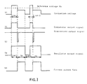
- an pulse of voltage in open circuit is represented at (a), and an pulse of voltage in working conditions at (b) and (c).
- Represented at (d) and (e) is the pulse of current corresponding to each of the above.
- the pulse In open circuit, i.e. when the electrode and the part are separated by a distance greater than that of ionization, the pulse has the shape represented at (a). This pulse has had no effect, so that it is a lost impulse. In (b), the voltage already represents a distinct shape since in this case both electrodes will be at the correct distance, and therefore the ionization will have been produced. The time “t ion” is the time of ionization after which the impulse of current would have circulated between both electrodes. At (c) we see another voltage pulse which presents a longer time of ionization than the previous one.
- a system for being able to detect the instant at which these abnormal discharges are going to be produced is by observing the peak tension of ionization, since before the degenerative phenomenon is produced, it is possible to observe that these peak voltage diminish or even arrive at total cancellsion, so this makes it possible to take pertinent measures to attack the problem before it worsens.
- the system of temporary withdrawal of the electrode also has another disadvantage in that it is totally independent of the conditions of work. Frequently the electrode withdraws when it is not needed, and fails to withdraw when it is needed. Giving this alternating movement to the electrode brings about a spectacular reduction in the performance of the machine, since during these to and fro intervals, the machine does not erode. So if we add up these fractions of time lost at the end of a working day, the total ineffective time can be considerable, with a corresponding coniderable loss of productivity.
- the pause times are totally independent of the pulse times, so that at each new regulation of the pulse time, it is necessary to regulate the pause time to obtain good stability and performance in each new regime selected.
- the ratio is maintained constant, since the pause time is always expressed as so many percent of the pulse selected.
- the initial peak of current can be reinforced by the fact that, due to the parasitic capacities present in the circuit and capacity between electrode and part, if these capacities are loaded before the ionization, they discharge their energy at the moment the ionization is produced, with an initial energy of 1/2 CV2, C being the capacity and V the open circuit voltage.
- the EP-A-0 052 197 discloses a stepped waveshape like in other documents of the art, each steps having a vertical leading edge.
- the different stages of current are disposed in such a way that the discharge of each of them is produced sequentially and preferably regulated by a code determined to be able to produce the whole range of necessary values of current, with a minimum number of them, such as, for example, the BCD code.
- the interval of time between each discharge of the stages is, in the same way, variable at will, so as to be able to produce the desired delay between each one of them.
- the first step of power supplies an pulse of current the value of whch should be equal to or slightly more than the intensity of current of maintenance of the discharge, and always less than the working current selected. It should be noted that the maintenance current is the minimum value of intensity, below which the discharge of each pulse is made unstable and its establishment unpredictable.
- a circuit detects that this is the case and sets off a programmable counter which begins to count pulses proceeding from the time base, the frequency of which is much higher than those of the working pulses, and once the preselected count has been reached, the circuit gives a signal of conduction to the following stage of power, which supplies an pulse of current stronger than the previous one, with a certain delay in respect of the first.
- the third stage will be connected at the end of a certain time after the second has been connected, and so on.
- this spacing out can be made in various jumps so that the selected currents increase progressively until they arrive at the desired peak value, and from that moment onwards, the impulse continues normally.
- the transistors can always work with perfect switching, permitting unlimited adjustment in the breadth and height of the step in question.
- this first stage of supply can be equipped with means for varying the slope of the rising side of the current, taking especial account of the fact that in spite of what has been said about the dissipation of power, and given that in this stage the current is low, it would not therefore present problems of heat dissipation.
- the method can be applied to any system for producing impulses, whether or not the pulses are isoenergetic; if they are not, however, there could be a considerable loss of performance in the machine, since if the time of ionization is considerably prolonged, the strong current pulse could fall outside the period of duration of the pulse, i.e. during the pause, which would mean that these impulses would be irremediately lost and therefore would not contribute to the useful work.
- the stepping can be produced in the failing side of the current pulse, which would make it possible to obtain an additional reduction of the wear, albeit a less significant one, since in consequence a small inversion of the current takes place, which may be produced when the instantaneous pulse of strong current is cut, there being - as there always are - parasitic inductances in the circuit.
- A represents the general source of supply
- B an oscillator circuit
- C a decision logic
- D the power amplifier
- E the servo activating the electrode
- F the electrode
- G the part to be worked.
- Block B is shown in fig. 4, and in it we see that b1 represents a clock generating pulses with a frequency much higher than that of the working pulses of the machine. It will preferably be a quartz crystal clock, so as to guarantee good precision and stability.. We will suppose that this clock works at a frequency of 100 MHz.
- the pulses proceeding from the clock enter block b2 which is a frequency divider composed of a fixed division unit of value 100 and a unit that can be programmed from outside by means of the preselectors Pr, or via a computer. This divider constitutes the generator of pause times.
- the pulses leaving block b2 pass to block b3, consisting of another programmable frequency divider, and this is the one which generates the pulse times of the working current.
- the output from this block is applied to a bistable circuit (b4) which changes state with each pulse that reaches it. Its output arrives a block b1 in such a way that in each of its states it selects alternatively the fixed counter or the programmable counter.
- a bistable circuit (b4) which changes state with each pulse that reaches it. Its output arrives a block b1 in such a way that in each of its states it selects alternatively the fixed counter or the programmable counter.
- This can be a single signal giving a fixed and pre-established pause width, or it can preferably be variable in shape, so that if the problem has not been solved with the first width, the following anomalous pulse produced will increase the factor of division by a certain value, and so on at each new incorrect pulse.
- a second comparator which is adjusted at a higher level, gives the order to withdraw the electrode rapidly for cleaning the space between electrode and part. If for any reason this rapid withdrawal does not take place, it also emits a sigal which inhibits the production of pulses of strong current, so that it is practically impossible for an arc to be produced.
- Both divider b3 and b2 are also provided with an asynchronous input by which it is possible to reload the counters at any moment, reinitiating the count from that moment onwards, and in this way it is possible to obtain an pulse time that is perfectly controlled in breadth.
- This signal arrives at the counters from the moment at which the detector circuit, which will be described below, has detected that the ionization has been produced.
- VC1, VC2 and VC are dynamic comparators of the level of ionization voltage. Each of them is adjusted at the suitable detection value. Their detection is made pulse by pulse, so as to obtain a total real-time monitoring of the working conditions.
- the comparators VC4 and VC5 measure the average working voltage, or they can also be accumulators recording the number of anomalous pulses as a function of the time, or also digital comparators which record the correct pulses that should be produced and those that actually are produced.
- comparators have an adjustable level of comparation which, in the case of VC5 can have an outside control for making the adjustment manually if desired.
- the voltage comparator VC1 In the block VC6 is included the voltage comparator VC1 and a logic circuit which converts the level of voltage compared into a synchronization signal which is applied to the frequency dividers b2 and b3 of the oscillator block, which re-initiates the count of pulse time from the instant in which ionization is produced, according to the time diagrams of fig. 7, in which diagram S1 represents the electrode-part voltage, and in it we can see the different times of ionization "t ion" 1 and "t ion"2.
- V comp. represents the level of comparison of the comparator VC1.
- comparator VC1 (signal S2) appears only the time of ionization of diagram S1, and it represents the voltage which has been able to cross the threshold of the level of comparison V comp.
- the delay circuit (block C7) includes the comparator VC2, a logic, and some output stages, preferably optocoupled, which are directly attached to the power stages.
- the comparator of this circuit detects, like the VC1, the level of ionization voltage, and its ouptut is applied to a delay generator circuit, to which is also applied the output of the general oscillator. With both inputs, and via some bistables and a frequency divider chain, some outputs are generated, out of phase with one another, according to the time diagram of fig 8 in which, for greater clarity, we show only two outputs which is the minimum necessary for the system to work.
- the output S7 is a faithful reflection of the signal of the oscillator which, preferably via an optocoupler as we said above, is input into the stage generating the pulse of weak current for the supply circuit of the ionization.
- the output S10 is out of phase with S7 which is the sum of the programmed delay plus the time of ionization.
- This output via another optocoupler, is input into the following stage of strong current. This means that the signal S7, amplified in the stage of weak intensity power, intiates the discharge with an ionization time "t ion" 1 according to the signal E2.
- this divider chain emits a signal S11 to one of the bistables of the circuit which, on changing state, generates a signal S9, and the optocouplers mentioned above give the signal S10 to the amplification stages of strong current of value Ib of the graph I s , (fig. 8).
- the pause widening system block C8 includes the comparator VC3 and a decision logic.
- the comparator analyses the level of ionization voltage of each pulse signal S13, generating an output signal S14 in cases where it is higher than the level of comparison.
- the logic circuit acts as follows: a bistable goes into one of its two states at the beginning (X) of each pulses arriving at if from the oscillator, and changes state with the descending side (Y) of each pulse of ionization via the comparator. See fig. 9.
- the circuit continues to suppose that the following pulse is going to be anomalous, and consequently programmes a longer pause, but as soon as the ionization edge which is characteristic of normal pulses appears, the circuit switches over and programmes a normal pause, doing so while the current pulse is taking place.
- the circuit C9 is the one responsible for producing the signal for the withdrawal of the servo, and consists of a average voltage comparator VC4 and of a logic by means of which a signal is sent for interrupting the work pulses and thus leaving the electrode and the part without voltage; at the same time, another signal is sent to counters for them to record the pulses emitted by an encoder coupled to the servo. When then counters arrive at a predetermined number, the servo signal is inverted, and the servo begins to approach the part, at the same time as the counters begin to count down.
- the circuit C10 is a servo regulation circuit and consists of a voltage comparator and a differential amplifier which supplies an output of ⁇ 10V capable of controlling a servo-valve, if the servo is of the hydraulic type, or a speed regulator with four quadrants regulation if the servo is of the electro-mechanical type, with a DC motor, or a voltage-frequency converter if the motor is of the stepping type.
- Block D is a power amplifier composed of transistors working in switching, in which it is possible to use bipolar transistors and/or MOSFETS, although the latter are preferable in view of their characteristics of high switching speed, low control power, absence of second break, etc, these advantages being already known in the art.
Landscapes
- Engineering & Computer Science (AREA)
- Mechanical Engineering (AREA)
- Electrical Discharge Machining, Electrochemical Machining, And Combined Machining (AREA)
- Refinement Of Pig-Iron, Manufacture Of Cast Iron, And Steel Manufacture Other Than In Revolving Furnaces (AREA)
Claims (13)
- Verfahren zur Verminderung des Elektrodenverschleißes in Elektroerosionsmaschinen mit einer Schaltung zur Steuerung der elektrischen Entladung zwischen einer Elektrode und einem zu bearbeitenden Teil, sowie zur sequentiellen Erzeugung von Strompulsen, die in bezug auf Stromwerte verteilt und durch Taktpulse synchronisiert sind, um sukzessiv inkrementale Stromwerte zu erzeugen, zwischen denen eine bestimmte Zeitverzögerung liegt, um eine ansteigende Seite an den Strompulsen zu erhalten,
gekennzeichnet durch:- Zuführung eines schwachen Stroms in gewichteter Form von einer ersten Leistungsstufe der Steuerschaltung, der eine ansteigende Seite für die Strompulse in Form einer variablen Schräge und/oder Kurve erzeugt und- Zuführung eines starken Stroms in gewichteter Form von einer Gruppe von mindestens einer zweiten Leistungsstufe der Steuerschaltung, der sich an die ansteigende Seite des schwachen Stroms anschließt oder von dieser abgesetzt ist und eine ansteigende Seite der Pulse in gestufter Form erzeugt, wobei die Breite jeder Stufe eine Funktion der Zeit und die Höhe eine Funktion des Stromes ist. - Verfahren zur Verminderung des Elektrodenverschleißes in Elektroerosionsmaschinen nach Anspruch 1,
dadurch gekennzeichnet, daß die Art des Betriebes der starken Stromgruppe von dem Moment des Empfangs des Verzögerungssignals an in bezug auf die erste Leistungsstufe des schwachen Stroms angeschlossen oder abgesetzt sein kann. - Verfahren zur Verminderung des Elektrodenverschleißes in Elektroerosionsmaschinen nach Anspruch 1 oder 2,
dadurch gekennzeichnet, daß die Abtrennung der Stufen starken Stroms augenblicklich oder stufenweise an der abfallenden Seite erfolgen kann. - Verfahren zur Verminderung des Elektrodenverschleißes in Elektroerosionsmaschinen nach Anspruch 1,
dadurch gekennzeichnet, daß der erste Puls des schwachen Stroms auch nach Erzeugung der Pulse hohen Stroms weiter arbeiten kann oder während dieses Betriebes unterdrückt wird, da der Kanal bereits aufgebaut worden ist. - Verfahren zur Verminderung des Elektrodenverschleißes in Elektroerosionsmaschinen nach mindestens einem der Ansprüche 1 bis 4,
dadurch gekennzeichnet, daß das Verzögerungssystem zwischen den Pulsen schwachen Stroms und den Pulsen starken Stroms zur Speisung von Akkumulatorschaltungen dient, wobei sich der Akkumulator geringer Energie zuerst entlädt und nachfolgend diejenigen mit höherer Energie. - Verfahren zur Verminderung des Elektrodenverschleißes in Elektroerosionsmaschinen nach mindestens einem der Ansprüche 1 bis 5,
dadurch gekennzeichnet, daß eine Pegel-Komparatorschaltung zur kontinuierlichen Real-Time-Überwachung der Erzeugung einer Ionisation bei jedem Puls vorgesehen ist, die in diesem Fall ein Signal zur erneuten Ladung zu Zählern sendet, die die Pulszeit steuern, die Zählung von diesem Moment an wieder beginnen und Strompulse mit gleicher Energie erhalten. - Verfahren zur Verminderung des Elektrodenverschleißes in Elektroerosionsmaschinen nach mindestens einem der Ansprüche 1 bis 6,
dadurch gekennzeichnet, daß eine zweite Komparatorschaltung vorgesehen ist, die das Vorhandensein von Ionisationsströmen zwischen einer Elektrode und einem zu bearbeitenden Teil überwacht, die die Unterbrechungszeit verlängert, wenn absehbar ist, daß der Puls anormal wird und dann durch Änderung des Zustandes mittels der abfallenden Seite des Ionisationspulses zu dem Zustand normaler Unterbrechung während des Arbeitspulses übergeht. - Verfahren zur Verminderung des Elektrodenverschleißes in Elektroerosionsmaschinen nach mindestens einem der Ansprüche 1 bis 7,
dadurch gekennzeichnet, daß durch eine kontinuierliche Folge anormaler Pulse die Unterbrechungszeit verlängert wird, der durchschnittliche Wert der Spannung zwischen der Elektrode und dem Teil reduziert und von einem Servo-Regelvergleicher erfaßt wird, der eine schnelle Rückbewegung der Servoeinrichtung bewirkt, den niedrigeren Pegel erfaßt und auf die schnelle Rückbewegung der Servoeinrichtung umschaltet. - Verfahren zur Verminderung des Elektrodenverschleißes in Elektroerosionsmaschinen nach mindestens einem der Ansprüche 1 bis 8,
dadurch gekennzeichnet, daß in dem Fall, in dem die Servoeinrichtung und folglich die Elektrode nicht zurückbewegt wurde, die Unterbrechungszeit schrittweise so lange vergrößert wird, bis ein Signal auftritt, welches die Stufen mit stärkerem Strom sperrt. - Verfahren zur Verminderung des Elektrodenverschleißes in Elektroerosionsmaschinen nach mindestens einem der Ansprüche 1 bis 9,
dadurch gekennzeichnet, daß eine Schaltung vorgesehen ist, die Unterbrechungszeiten erzeugt, die Prozentsätze der Pulszeiten darstellen, wobei eine konstante Beziehung zwischen beiden aufrechterhalten wird. - Verfahren zur Verminderung des Elektrodenverschleißes in Elektroerosionsmaschinen nach mindestens einem der Ansprüche 1 bis 10,
dadurch gekennzeichnet, daß das System auch zur Steuerung mittels eines kommutierenden Elementes parallel mit der Last oder in jeder anderen Kombination mit den anderen Elementen in Serienschaltung anwendbar ist. - Verfahren zur Verminderung des Elektrodenverschleißes in Elektroerosionsmaschinen nach mindestens einem der Ansprüche 1 bis 11,
dadurch gekennzeichnet, daß eine Komparatorschaltung für einen Mittelwert der Spannung zwischen einer Elektrode und dem zu bearbeitenden Teil vorgesehen ist, die ein Signal zum Zurückbewegen der Elektrode erzeugt, wenn der Pegel unter einen erwarteten Wert herabfällt, was eine Anzeige für anormale Entladungen sein würde. - Verfahren zur Verminderung des Elektrodenverschleißes in Elektroerosionsmaschinen nach Anspruch 12,
dadurch gekennzeichnet, daß das Signal zum Zurückbewegen der Elektrode einen die Elektrode aktivierenden Befehl zur Servoeinrichtung sendet und zur gleichen Zeit eine Zählerkette aktiviert, welche die von der Servoeinrichtung bei ihrer zurückziehenden Bewegung über einen Codierer gesendeten Pulse aufzeichnet, so daß bei Erreichen eines bestimmten Zählerstandes die Servoeinrichtung ein inverses Signal empfängt, welches eine Zählung in entgegengesetzter Richtung oder nach unten beginnt und vor Erreichen des Nullwertes die Servoeinrichtung mit reduzierter Geschwindigkeit verbindet, um zu vermeiden, daß die Elektrode an den Teil anschlägt.
Priority Applications (1)
| Application Number | Priority Date | Filing Date | Title |
|---|---|---|---|
| AT89870179T ATE91449T1 (de) | 1988-11-11 | 1989-11-10 | Verfahren zur verminderung des elektrodenverschleisses in elektroerosionsmaschinen. |
Applications Claiming Priority (2)
| Application Number | Priority Date | Filing Date | Title |
|---|---|---|---|
| ES8803419A ES2009110A6 (es) | 1988-11-11 | 1988-11-11 | Metodo para reducir el desgaste del electrodo en maquinas de mecaniza-do por electroerosion. |
| ES8803419 | 1988-11-11 |
Publications (2)
| Publication Number | Publication Date |
|---|---|
| EP0368833A1 EP0368833A1 (de) | 1990-05-16 |
| EP0368833B1 true EP0368833B1 (de) | 1993-07-14 |
Family
ID=8258882
Family Applications (1)
| Application Number | Title | Priority Date | Filing Date |
|---|---|---|---|
| EP89870179A Expired - Lifetime EP0368833B1 (de) | 1988-11-11 | 1989-11-10 | Verfahren zur Verminderung des Elektrodenverschleisses in Elektroerosionsmaschinen |
Country Status (6)
| Country | Link |
|---|---|
| US (1) | US5187341A (de) |
| EP (1) | EP0368833B1 (de) |
| JP (1) | JPH02237720A (de) |
| AT (1) | ATE91449T1 (de) |
| DE (1) | DE68907558T2 (de) |
| ES (1) | ES2009110A6 (de) |
Families Citing this family (11)
| Publication number | Priority date | Publication date | Assignee | Title |
|---|---|---|---|---|
| US5126525A (en) * | 1988-11-01 | 1992-06-30 | Sodick Co., Ltd. | Power supply system for electric discharge machines |
| JP2914102B2 (ja) * | 1993-06-30 | 1999-06-28 | 三菱電機株式会社 | 放電加工機 |
| US5872347A (en) * | 1997-06-24 | 1999-02-16 | Industrial Technology Research Institute | Method and device for controlling discharging current slope of wire cut electrical discharge machine |
| US7596459B2 (en) * | 2001-02-28 | 2009-09-29 | Quadlogic Controls Corporation | Apparatus and methods for multi-channel electric metering |
| US6717094B2 (en) | 2002-07-22 | 2004-04-06 | Edward L. Beaumont | Electrical discharge machine and methods of establishing zero set conditions for operation thereof |
| EP1464430B1 (de) * | 2003-04-02 | 2008-10-22 | Agie Sa | Verfahren und Vorrichtung zum funkenerosiven Bearbeiten eines Werkstückes |
| EP1793235A1 (de) * | 2005-11-30 | 2007-06-06 | ABB Technology AG | Überwachungssystem für Hochspannungsschalter |
| DE102010005617A1 (de) * | 2009-10-01 | 2011-04-07 | Kjellberg Finsterwalde Plasma Und Maschinen Gmbh | Verfahren zum Plasmaschneiden eines Werkstücks mittels einer Plasmaschneidanlage |
| JP5204321B1 (ja) * | 2012-02-01 | 2013-06-05 | ファナック株式会社 | 加工状態を検出し極間の平均電圧を求めるワイヤ放電加工機 |
| DE102012105362A1 (de) * | 2012-06-20 | 2013-12-24 | Trinamic Motion Control Gmbh & Co. Kg | Verfahren und Schaltungsanordnung zur Ansteuerung eines Schrittmotors |
| JP5650787B2 (ja) * | 2013-04-12 | 2015-01-07 | ファナック株式会社 | 放電開始を判定する機能を有するガスレーザ発振器 |
Family Cites Families (20)
| Publication number | Priority date | Publication date | Assignee | Title |
|---|---|---|---|---|
| US3916138A (en) * | 1964-02-25 | 1975-10-28 | Charmilles Sa Ateliers | Apparatus for machining through varying-frequency constant-duration pulse-controlled electric discharges |
| NL7116823A (de) * | 1971-12-08 | 1973-06-13 | ||
| US3809848A (en) * | 1972-12-14 | 1974-05-07 | Colt Ind Operating Corp | Digitally controlled power supply for electrical discharge machining apparatus |
| JPS5854937B2 (ja) * | 1973-02-19 | 1983-12-07 | 三菱電機株式会社 | ホウデンカコウセイギヨホウホウ |
| US3974357A (en) * | 1973-03-22 | 1976-08-10 | Mitsubishi Denki Kabushiki Kaisha | Process and apparatus for electrical discharge shaping using sequential switching |
| US3825715A (en) * | 1973-05-29 | 1974-07-23 | Mitsubishi Electric Corp | Process for controlling electrical discharge shaping |
| US4292490A (en) * | 1977-05-06 | 1981-09-29 | Colt Industries Operating Corp. | Electrical discharge machining power supply with digitally controlled on and off time and protective system |
| GB2016346B (en) * | 1978-01-17 | 1982-02-17 | Agemaspark Ltd | Spark erosion machines |
| JPS6055249B2 (ja) * | 1979-02-09 | 1985-12-04 | 株式会社井上ジャパックス研究所 | 放電加工装置 |
| DE3043339A1 (de) * | 1980-11-17 | 1982-06-03 | Friedrich Deckel AG, 8000 München | Generator fuer eine elektro-erosionsmaschine |
| JPS58102628A (ja) * | 1981-12-14 | 1983-06-18 | Inoue Japax Res Inc | 放電加工装置 |
| JPS59227327A (ja) * | 1983-06-08 | 1984-12-20 | Fanuc Ltd | 放電加工機の電極後退制御方式 |
| JPS6125722A (ja) * | 1984-07-10 | 1986-02-04 | Mitsubishi Electric Corp | 放電加工装置 |
| GB2163277B (en) * | 1984-07-20 | 1988-10-26 | Amada Co Ltd | A method of and apparatus for controlling the tool electrode in an electrical discharge machine tool |
| US4700039A (en) * | 1984-08-08 | 1987-10-13 | Amada Company, Limited | Method and device for controlling the tool electrode in an electrical discharge machine tool |
| JPS6188770A (ja) * | 1984-10-05 | 1986-05-07 | Amada Co Ltd | 放電加工装置の電流制御回路 |
| DE3622520A1 (de) * | 1986-07-04 | 1988-01-07 | Deckel Ag Friedrich | Verfahren und einrichtung zur ueberwachung eines funkenerodier-prozesses in einer funkenerodiermaschine |
| JPS63156618A (ja) * | 1986-12-22 | 1988-06-29 | Hoden Seimitsu Kako Kenkyusho Ltd | 放電加工装置 |
| JPS63169220A (ja) * | 1986-12-27 | 1988-07-13 | Shizuoka Seiki Co Ltd | 電源装置 |
| JPS63200918A (ja) * | 1987-02-16 | 1988-08-19 | Hitachi Seiko Ltd | 放電加工装置 |
-
1988
- 1988-11-11 ES ES8803419A patent/ES2009110A6/es not_active Expired
-
1989
- 1989-11-09 US US07/435,016 patent/US5187341A/en not_active Expired - Fee Related
- 1989-11-10 EP EP89870179A patent/EP0368833B1/de not_active Expired - Lifetime
- 1989-11-10 DE DE89870179T patent/DE68907558T2/de not_active Expired - Fee Related
- 1989-11-10 AT AT89870179T patent/ATE91449T1/de not_active IP Right Cessation
- 1989-11-13 JP JP1294780A patent/JPH02237720A/ja active Pending
Also Published As
| Publication number | Publication date |
|---|---|
| DE68907558T2 (de) | 1994-02-17 |
| ATE91449T1 (de) | 1993-07-15 |
| DE68907558D1 (de) | 1993-08-19 |
| JPH02237720A (ja) | 1990-09-20 |
| US5187341A (en) | 1993-02-16 |
| ES2009110A6 (es) | 1989-08-16 |
| EP0368833A1 (de) | 1990-05-16 |
Similar Documents
| Publication | Publication Date | Title |
|---|---|---|
| EP0368833B1 (de) | Verfahren zur Verminderung des Elektrodenverschleisses in Elektroerosionsmaschinen | |
| US3604885A (en) | Edm power supply for generating self-adaptive discharge pulses | |
| US4004123A (en) | Method of and system for the controlling of an apparatus for the electric discharge machining of a workpiece | |
| US3864541A (en) | System for the controlling of an apparatus for the electric discharge machining etc. | |
| DE2954545C2 (de) | ||
| US4507533A (en) | Power supply circuit for electrical machining | |
| US3504154A (en) | Edm power supply with separate sources of gap ionizing potential and material eroding energy | |
| KR100555356B1 (ko) | 와이어 방전가공기의 가공전원장치 | |
| EP2752266B1 (de) | Stromquelle zum Funkenerodieren | |
| US3087044A (en) | Electric power supply apparatus for electric discharge machining | |
| US5874703A (en) | Method and apparatus for impulse generator for electroerosive machining of workpieces | |
| US3666906A (en) | Carbide deposition structure and method | |
| US3035149A (en) | Discharge machining apparatus and method | |
| US4072842A (en) | Electro-erosion machine tool and a pulse generator for use in such a machine tool | |
| KR100556325B1 (ko) | 전기 방전 가공 방법 및 장치 | |
| JPS6211971B2 (de) | ||
| USRE28734E (en) | EDM power supply for generating self-adaptive discharge pulses | |
| US4357516A (en) | EDM Method and apparatus utilizing successive trains of elementary pulses with controlled pulse-off periods | |
| US4503309A (en) | EDM Method and apparatus with successive trains of intermittently enlarged elementary pulses | |
| JPS6238092B2 (de) | ||
| Blatnik et al. | Percentage of harmful discharges for surface current density monitoring in electrical discharge machining process | |
| US5171957A (en) | Generator for electric discharge machining of metallic work pieces by means of an electrode consisting of liquid or solid material | |
| JPS5847292B2 (ja) | ホウデンカコウソウチ | |
| RU2074067C1 (ru) | Способ управления технологическим током при электроэрозионной обработке | |
| USRE26090E (en) | Kiyoshi inoue |
Legal Events
| Date | Code | Title | Description |
|---|---|---|---|
| PUAI | Public reference made under article 153(3) epc to a published international application that has entered the european phase |
Free format text: ORIGINAL CODE: 0009012 |
|
| AK | Designated contracting states |
Kind code of ref document: A1 Designated state(s): AT BE CH DE ES FR GB GR IT LI LU NL SE |
|
| 17P | Request for examination filed |
Effective date: 19901113 |
|
| 17Q | First examination report despatched |
Effective date: 19910830 |
|
| GRAA | (expected) grant |
Free format text: ORIGINAL CODE: 0009210 |
|
| AK | Designated contracting states |
Kind code of ref document: B1 Designated state(s): AT BE CH DE ES FR GB GR IT LI LU NL SE |
|
| PG25 | Lapsed in a contracting state [announced via postgrant information from national office to epo] |
Ref country code: IT Free format text: LAPSE BECAUSE OF FAILURE TO SUBMIT A TRANSLATION OF THE DESCRIPTION OR TO PAY THE FEE WITHIN THE PRE;WARNING: LAPSES OF ITALIAN PATENTS WITH EFFECTIVE DATE BEFORE 2007 MAY HAVE OCCURRED AT ANY TIME BEFORE 2007. THE CORRECT EFFECTIVE DATE MAY BE DIFFERENT FROM THE ONE RECORDED.SCRIBED TIME-LIMIT Effective date: 19930714 Ref country code: FR Effective date: 19930714 Ref country code: NL Effective date: 19930714 Ref country code: GR Free format text: LAPSE BECAUSE OF FAILURE TO SUBMIT A TRANSLATION OF THE DESCRIPTION OR TO PAY THE FEE WITHIN THE PRESCRIBED TIME-LIMIT Effective date: 19930714 Ref country code: ES Free format text: THE PATENT HAS BEEN ANNULLED BY A DECISION OF A NATIONAL AUTHORITY Effective date: 19930714 Ref country code: AT Effective date: 19930714 Ref country code: SE Effective date: 19930714 Ref country code: BE Effective date: 19930714 |
|
| REF | Corresponds to: |
Ref document number: 91449 Country of ref document: AT Date of ref document: 19930715 Kind code of ref document: T |
|
| REF | Corresponds to: |
Ref document number: 68907558 Country of ref document: DE Date of ref document: 19930819 |
|
| PG25 | Lapsed in a contracting state [announced via postgrant information from national office to epo] |
Ref country code: LU Free format text: LAPSE BECAUSE OF NON-PAYMENT OF DUE FEES Effective date: 19931130 |
|
| EN | Fr: translation not filed | ||
| NLV1 | Nl: lapsed or annulled due to failure to fulfill the requirements of art. 29p and 29m of the patents act | ||
| PLBE | No opposition filed within time limit |
Free format text: ORIGINAL CODE: 0009261 |
|
| STAA | Information on the status of an ep patent application or granted ep patent |
Free format text: STATUS: NO OPPOSITION FILED WITHIN TIME LIMIT |
|
| 26N | No opposition filed | ||
| PGFP | Annual fee paid to national office [announced via postgrant information from national office to epo] |
Ref country code: GB Payment date: 19971106 Year of fee payment: 9 |
|
| PGFP | Annual fee paid to national office [announced via postgrant information from national office to epo] |
Ref country code: CH Payment date: 19971110 Year of fee payment: 9 |
|
| PGFP | Annual fee paid to national office [announced via postgrant information from national office to epo] |
Ref country code: DE Payment date: 19971127 Year of fee payment: 9 |
|
| PG25 | Lapsed in a contracting state [announced via postgrant information from national office to epo] |
Ref country code: GB Free format text: LAPSE BECAUSE OF NON-PAYMENT OF DUE FEES Effective date: 19981110 |
|
| PG25 | Lapsed in a contracting state [announced via postgrant information from national office to epo] |
Ref country code: LI Free format text: LAPSE BECAUSE OF NON-PAYMENT OF DUE FEES Effective date: 19981130 Ref country code: CH Free format text: LAPSE BECAUSE OF NON-PAYMENT OF DUE FEES Effective date: 19981130 |
|
| GBPC | Gb: european patent ceased through non-payment of renewal fee |
Effective date: 19981110 |
|
| REG | Reference to a national code |
Ref country code: CH Ref legal event code: PL |
|
| PG25 | Lapsed in a contracting state [announced via postgrant information from national office to epo] |
Ref country code: DE Free format text: LAPSE BECAUSE OF NON-PAYMENT OF DUE FEES Effective date: 19990901 |