EP0368838A1 - Vorrichtung zur Absicherung von nicht bzw. mässig standfesten kohäsionslosen bis leicht kohäsiven geologischen Formationen - Google Patents
Vorrichtung zur Absicherung von nicht bzw. mässig standfesten kohäsionslosen bis leicht kohäsiven geologischen Formationen Download PDFInfo
- Publication number
- EP0368838A1 EP0368838A1 EP89890281A EP89890281A EP0368838A1 EP 0368838 A1 EP0368838 A1 EP 0368838A1 EP 89890281 A EP89890281 A EP 89890281A EP 89890281 A EP89890281 A EP 89890281A EP 0368838 A1 EP0368838 A1 EP 0368838A1
- Authority
- EP
- European Patent Office
- Prior art keywords
- injection
- channel
- anchor
- drill
- spit
- Prior art date
- Legal status (The legal status is an assumption and is not a legal conclusion. Google has not performed a legal analysis and makes no representation as to the accuracy of the status listed.)
- Granted
Links
- 230000015572 biosynthetic process Effects 0.000 title claims abstract description 10
- 238000005755 formation reaction Methods 0.000 title claims abstract description 10
- 238000007596 consolidation process Methods 0.000 title 1
- 238000002347 injection Methods 0.000 claims abstract description 28
- 239000007924 injection Substances 0.000 claims abstract description 28
- 238000000034 method Methods 0.000 claims abstract description 19
- 150000001875 compounds Chemical class 0.000 claims abstract description 14
- 238000000605 extraction Methods 0.000 claims abstract description 3
- 238000004519 manufacturing process Methods 0.000 claims abstract description 3
- 238000005553 drilling Methods 0.000 claims description 17
- 238000011010 flushing procedure Methods 0.000 claims description 7
- 238000005520 cutting process Methods 0.000 claims description 5
- 238000009412 basement excavation Methods 0.000 claims description 3
- 239000011435 rock Substances 0.000 description 7
- 238000010276 construction Methods 0.000 description 5
- 239000007788 liquid Substances 0.000 description 4
- 230000005641 tunneling Effects 0.000 description 3
- 229910052782 aluminium Inorganic materials 0.000 description 2
- XAGFODPZIPBFFR-UHFFFAOYSA-N aluminium Chemical compound [Al] XAGFODPZIPBFFR-UHFFFAOYSA-N 0.000 description 2
- 238000005516 engineering process Methods 0.000 description 2
- 241001295925 Gegenes Species 0.000 description 1
- 239000011083 cement mortar Substances 0.000 description 1
- 239000003795 chemical substances by application Substances 0.000 description 1
- 238000005253 cladding Methods 0.000 description 1
- 238000005260 corrosion Methods 0.000 description 1
- 230000007797 corrosion Effects 0.000 description 1
- 230000000694 effects Effects 0.000 description 1
- 230000008014 freezing Effects 0.000 description 1
- 238000007710 freezing Methods 0.000 description 1
- ZZUFCTLCJUWOSV-UHFFFAOYSA-N furosemide Chemical compound C1=C(Cl)C(S(=O)(=O)N)=CC(C(O)=O)=C1NCC1=CC=CO1 ZZUFCTLCJUWOSV-UHFFFAOYSA-N 0.000 description 1
- 238000003780 insertion Methods 0.000 description 1
- 230000037431 insertion Effects 0.000 description 1
- 230000002262 irrigation Effects 0.000 description 1
- 238000003973 irrigation Methods 0.000 description 1
- 239000000463 material Substances 0.000 description 1
- 229910052751 metal Inorganic materials 0.000 description 1
- 239000002184 metal Substances 0.000 description 1
- 239000000203 mixture Substances 0.000 description 1
- 239000005445 natural material Substances 0.000 description 1
- 238000009527 percussion Methods 0.000 description 1
- 239000004033 plastic Substances 0.000 description 1
- 229920003002 synthetic resin Polymers 0.000 description 1
- 239000000057 synthetic resin Substances 0.000 description 1
Images

Classifications
-
- E—FIXED CONSTRUCTIONS
- E21—EARTH OR ROCK DRILLING; MINING
- E21D—SHAFTS; TUNNELS; GALLERIES; LARGE UNDERGROUND CHAMBERS
- E21D9/00—Tunnels or galleries, with or without linings; Methods or apparatus for making thereof; Layout of tunnels or galleries
- E21D9/001—Improving soil or rock, e.g. by freezing; Injections
-
- E—FIXED CONSTRUCTIONS
- E02—HYDRAULIC ENGINEERING; FOUNDATIONS; SOIL SHIFTING
- E02D—FOUNDATIONS; EXCAVATIONS; EMBANKMENTS; UNDERGROUND OR UNDERWATER STRUCTURES
- E02D5/00—Bulkheads, piles, or other structural elements specially adapted to foundation engineering
- E02D5/74—Means for anchoring structural elements or bulkheads
- E02D5/80—Ground anchors
-
- E—FIXED CONSTRUCTIONS
- E21—EARTH OR ROCK DRILLING; MINING
- E21D—SHAFTS; TUNNELS; GALLERIES; LARGE UNDERGROUND CHAMBERS
- E21D20/00—Setting anchoring-bolts
- E21D20/003—Machines for drilling anchor holes and setting anchor bolts
-
- E—FIXED CONSTRUCTIONS
- E21—EARTH OR ROCK DRILLING; MINING
- E21D—SHAFTS; TUNNELS; GALLERIES; LARGE UNDERGROUND CHAMBERS
- E21D21/00—Anchoring-bolts for roof, floor in galleries or longwall working, or shaft-lining protection
- E21D21/0026—Anchoring-bolts for roof, floor in galleries or longwall working, or shaft-lining protection characterised by constructional features of the bolts
- E21D21/0033—Anchoring-bolts for roof, floor in galleries or longwall working, or shaft-lining protection characterised by constructional features of the bolts having a jacket or outer tube
-
- E—FIXED CONSTRUCTIONS
- E21—EARTH OR ROCK DRILLING; MINING
- E21D—SHAFTS; TUNNELS; GALLERIES; LARGE UNDERGROUND CHAMBERS
- E21D21/00—Anchoring-bolts for roof, floor in galleries or longwall working, or shaft-lining protection
- E21D21/0026—Anchoring-bolts for roof, floor in galleries or longwall working, or shaft-lining protection characterised by constructional features of the bolts
- E21D21/0053—Anchoring-bolts in the form of lost drilling rods
Definitions
- the present invention relates to a method for securing non or moderately stable non-cohesive to slightly cohesive geological formations, in particular in the manufacture of tunnels, in which holes are first made in the formation, after completion of the holes, the drill pipe is withdrawn, during which Retracting a hardenable injection compound is pressed into the bore.
- Injection drill anchors and pre-attachments with pre-attachment plates, pre-attachment skewers and the like represent a further known variant of pre-securing. These safeguards can be introduced on site with relatively little outlay on equipment.
- a disadvantage of the injection drill anchor is that the drill bit remains in the borehole together with the anchor and is therefore lost. This leads to a relatively high expenditure of expensive material.
- Injection skewers (aluminum skewers) are also known, in which after drilling a borehole, the drill pipe is removed from the borehole, and an anchor or a skewer is inserted, which is poured into the borehole using a hardenable injection compound.
- This method has the disadvantage that several operations are required to carry it out, so that only slow work progress can be achieved.
- the hole can fall between the removal of the drill pipe and the insertion of the aluminum spike, so that further time-consuming operations are required.
- the object of the invention is to avoid the disadvantages mentioned and to provide a method for securing cavities or embankments which requires little mechanical effort and essentially a single operation.
- a spike or anchor is inserted into the bore with the drill string, which remains during the extraction in the bore and which is firmly connected to the formation by the injection compound.
- the expensive drill head can be recovered and reused until it wears out.
- the injection mass which is pressed in during the pulling of the drill pipe, holds the anchor in place and, after hardening, firmly connects it to the surrounding rock.
- reliable corrosion protection is achieved in this way.
- the drill string corresponds essentially to known drill string, with the exception that the bore is enlarged in the axial direction for receiving the armature.
- the hardenable injection mass is preferably pressed in via the flushing channel of the drill pipe. In this way, a particularly simple construction of the drill pipe can be achieved, since no additional channels are required to introduce the injection compound.
- a drilling injection screen is first produced by means of anchors or skewers which are inclined outwardly in the direction of advance, the excavation is then carried out under the drilling injection screen, and after the excavation the surrounding mountains are secured by injection anchors.
- an optimal connection of pre-securing with an additional securing of the surrounding mountains by means of injection anchors can be achieved, which brings about a substantial increase in the load-bearing capacity of the mountains.
- the invention relates to a device for carrying out the method with a drill pipe which has a channel in the axial direction and which has a drill head at its front end.
- This method is characterized by an anchor or spit in the channel is ejectable at the front. In this way it is possible for the spit to remain in the borehole together with the drill head while the drill rod is being pulled back. It is also advantageous if the anchor or spike used only fills a part of the cross-sectional area of the channel. In this way, a flushing liquid or an injection compound can be pressed to the drill head in the remaining cross section of the channel.
- the anchor or spit preferably has at least in one section a cross-section deviating from the circular shape, which is preferably arranged in the region of the drill head and which can be received non-rotatably by a corresponding section of the channel.
- the front end of the anchor or spike can be equipped with a device for drilling.
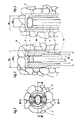
- the device according to the invention consists of a drill head 1 which is fixedly connected to a drill pipe 3.
- the drill pipe 3 has an annular cross section.
- the drill head 1 essentially has an oval outer cross section, the large radial dimension 11a of which extends beyond the outer diameter 13 of the drill pipe 3, and the small radial dimension 11b of which essentially corresponds to the outer diameter 13 of the drill pipe. In this way, a bore with a circular cross section is obtained during the advance, the diameter of which corresponds approximately to the large radial dimension 11a of the drill head 1.
- an anchor 5 is provided, which consists of a cylindrical body 5a and a thickened anchor head 5b.
- the cylindrical body 5a has a diameter 15 which is significantly smaller than the inner diameter 14 of the drill pipe 3. In this way, an annular space 4 remains free between the armature 5 and the drill pipe 3, through which an irrigation liquid or the like can be pumped to the drill head 1.
- the thickened anchor head 5b has a substantially oval cross section, the large radial dimension 15b of which is larger than the diameter 15 of the cylindrical body 5a, while the small radial dimension 15a corresponds approximately to the diameter 15 of the cylindrical body 5a.
- the thickened anchor head 5b of the anchor 5 is guided in a corresponding opening of the drill head 1, so much play being provided that passage of the flushing liquid is possible, but no rotational movement of the anchor 5 relative to the drill head 1 or the drill rod 3 is possible.
- the armature 5 is provided with a cutting edge 16, which participates in the drilling.
- the anchor 5 is inserted into the drill pipe 3. This can be done from the front or from the rear depending on the respective requirements. Subsequently, the drill pipe 3 is connected to a blow drilling unit, not shown, in a known manner. Now the drilling head 1 is driven into the mountains to be secured. During the advance, a flushing liquid is pressed through the annular space 4 to the drill head 1 in order to flush away the cuttings. The removal takes place via channels 9, which remain free between the side flats of the drill head 1 and the wall of the bore.
- the drilling process is ended and a hardenable In instead of the flushing agent Injection compound such as special cement mortar, synthetic resins, plastic / natural material mixtures and the like are pressed through the annular space 4.
- the drill pipe 3 together with the drill head 1 is withdrawn from the borehole.
- the pressure exerted on the thickened head 5b by the injection compound ensures that the armature 5 remains in its position. It is completely surrounded by the injection compound so that after the injection compound has hardened it is firmly poured into the borehole.
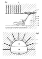
- a screen of anchors 5 ' is introduced by means of a drilling carriage 6, on which a percussion drilling device 7 is pivotably arranged, which are arranged radially outward in the direction of advance.
- the outbreak is carried out, for example, in the following order: 8a, 8b, 8c, 8d, 8e.
- anchors 5 ⁇ are introduced in the radial direction, which produce a vault effect in the surrounding rock, and to which any cladding of the tunnel can be attached.
- the method according to the invention can also be used for securing slope cuts, as shown in FIG. 6.
- An inclined slope is first provided with an incision 18a.
- the flank 19a is secured with anchors 5 ′′′.
- the incision is then gradually deepened around sections 18b, 18c and 18d.
- the flanks 19b, 19c, 19d are each secured analogously by means of further anchors, not shown.
- the method according to the invention allows loose rock to be reliably and easily secured in tunnel construction, but also in related fields of technology. In addition to accelerating the work process, qualitative improvements in tunnel construction can also be achieved.
Landscapes
- Engineering & Computer Science (AREA)
- Mining & Mineral Resources (AREA)
- Structural Engineering (AREA)
- Life Sciences & Earth Sciences (AREA)
- General Life Sciences & Earth Sciences (AREA)
- Geology (AREA)
- Geochemistry & Mineralogy (AREA)
- Paleontology (AREA)
- Soil Sciences (AREA)
- Environmental & Geological Engineering (AREA)
- Civil Engineering (AREA)
- General Engineering & Computer Science (AREA)
- Earth Drilling (AREA)
- Pit Excavations, Shoring, Fill Or Stabilisation Of Slopes (AREA)
- Piles And Underground Anchors (AREA)
- Drilling And Exploitation, And Mining Machines And Methods (AREA)
Abstract
Description
- Die vorliegende Erfindung betrifft ein Verfahren zur Absicherung von nicht bzw. mäßig standfesten kohäsionslosen bis leicht kohäsiven geologischen Formationen, insbesonders bei der Herstellung von Tunneln, bei dem zunächst Bohrungen in die Formation eingebracht werden, nach Fertigstellung der Bohrungen das Bohrgestänge zurückgezogen wird, wobei während des Zurückziehens eine erhärtbare Injektionsmasse in die Bohrung eingepreßt wird.
- Im Hohlraumbau werden längere Vortriebe in Weichgesteinen bzw. Lockergesteinen entweder vermieden oder mittels aufwendiger Maschinentechnik wie z.B. Schilde, hydrogestützte Ortsbrust u. dgl. oder mit umfangreichen Injektionsmaßnahmen bzw. mit Gefrierverfahren durchgeführt.
- Ein weiteres kompliziertes und teures Verfahren besteht in der Kombination von Druckluft und der neuen österreichischen Tunnelbauweise. Diese Verfahren haben den Nachteil, daß zu ihrer Durchführung ein großer maschineller Aufwand erforderlich ist. Insbesondere für kürzere Tunnels bzw. für den Fall, daß nur kleinere Abschnitte eines längeren Tunnels wegen Lockergesteines aufwendigere Stützmaßnahmen erfordern, sind solche Verfahren nicht mit vertretbarem Aufwand anwendbar.
- Eine weitere bekannte Variante der Voraussicherung stellen Injektionsbohranker sowie Vorpfändungen mit Vorpfändblechen, Vorpfändspießen und ähnlichem dar. Diese Sicherungen können mit relativ geringen apparativem Aufwand vor Ort eingebracht werden. Nachteilig ist jedoch beim Injektionsbohranker, daß die Bohrkrone zusammen mit dem Anker im Bohrloch verbleibt, und damit verloren ist. Dies führt zu relativ hohem Aufwand an teurem Material.
- Weiters sind Injektionsspieße (Aluvialspieße) bekannt, bei denen nach Erstellung eines Bohrloches das Bohrgestänge aus der Bohrung entfernt wird, und ein Anker bzw. ein Spieß eingeführt wird, der mittels einer erhärtbaren Injektionsmasse in das Bohrloch eingegossen wird. Dieses Verfahren hat den Nachteil, daß mehrere Arbeitsgänge zur Durchführung erforderlich sind, sodaß nur ein langsamer Arbeitsfortschritt erzielbar ist. Weiters kann die Bohrung zwischen dem Entfernen des Bohrgestänges und dem Einführen des Aluvialspießes zufallen, sodaß weitere zeitaufwendige Arbeitsvorgänge erforderlich sind.
- Die Aufgabe der Erfindung besteht darin, die genannten Nachteile zu vermeiden und ein Verfahren zur Absicherung von Hohlräumen bzw. Böschungen zu schaffen, das mit geringem maschinellen Aufwand und im wesentlichen einem einzigen Arbeitsgang auskommt.
- Erfindungsgemäß ist daher vorgesehen, daß mit dem Bohrgestänge ein Spieß oder Anker in die Bohrung eingebracht wird, der während des Herausziehens in der Bohrung verbleibt und der durch die Injektionsmasse fest mit der Formation verbunden wird. Auf diese Weise wird erreicht, daß außer dem Bohren und dem Herausziehen des Bohrers keine zusätzlichen Arbeitsgänge erforderlich sind. Der teure Bohrkopf kann dabei wiedergewonnen werden und bis zu seiner Abnützung wieterverwendet werden. Die Injektionsmasse, die während des Ziehens des Bohrgestänges durch dieses eingepreßt wird, hält den Anker in seiner Lage fest, und verbindet ihn nach dem Aushärten fest mit dem umgebenden Gestein. Weiters wird auf diese Weise ein zuverlässiger Korrosionsschutz erzielt. Das Bohrgestänge entspricht im wesentlichen bekannten Bohrgestängen mit der Ausnahme, daß die Bohrung in axialer Richtung zur Aufnahme des Ankers vergrößert ist.
- Vorzugsweise wird die erhärtbare Injektionsmasse über den Spülkanal des Bohrgestänges eingepreßt. Auf diese Weise kann ein besonders einfacher Aufbau des Bohrgestänges erzielt werden, da keinerlei zusätzlich Kanäle zum Einbringen der Injektionsmasse erforderlich sind.
- Es kann vorgesehen sein, daß zunächst ein Bohrinjektionsschirm mittels schräg in Vortriebsrichtung nach außen geneigter Anker oder Spieße hergestellt wird, darauf der Ausbruch unter dem Bohrinjektionsschirm durchgeführt wird, und nach dem Ausbruch das umgebende Gebirge mittels Injektionsankern gesichert wird. Auf diese Weise kann eine optimale Verbindung einer Voraussicherung mit einer zusätzlichen Sicherung des umgebenden Gebirges durch Injektionsanker erzielt werden, die eine wesentliche Erhöhung der Tragfestigkeit des Gebirges bewirkt.
- Weiters betrifft die Erfindung eine Vorrichtung zur Durchführung des Verfahrens mit einem Bohrgestänge, das in axialer Richtung einen Kanal aufweist, und das an seinem vorderen Ende einen Bohrkopf besitzt. Dieses Verfahren ist dadurch gekennzeichnet daß im Kanal ein Anker oder Spieß nach vorne ausstoßbar aufnehmbar ist. Auf diese Weise ist es möglich, daß der Spieß während des Zurückziehens des Bohregestänges samt Bohrkopf im Bohrloch verbleibt. Es ist weiters vorteilhaft, wenn der eingesetzte Anker oder Spieß nur einen Teil der Querschnittsfläche des Kanals ausfüllt. Auf diese Weise kann eine Spülflüssigkeit oder eine Injektionsmasse in dem verbleibenden Querschnitt des Kanals zum Bohrkopf gepreßt werden.
- Vorzugsweise weist der Anker oder Spieß zumindest in einem Abschnitt einen von der Kreisform abweichenden Querschnitt auf, der vorzugsweise im Bereich des Bohrkopfes angeordnet ist, und der unverdrehbar von einem entsprechenden Abschnitt des Kanals aufnehmbar ist. Insbesonders kann das vordere Ende des Ankers oder Spießes mit einer Einrichtung zum Bohren ausgestattet sein. Durch eine drehmomentfeste Verbindung des Ankers oder Spießes mit dem Bohrkopf bzw. dem Bohrgestänge und der Anordnung einer Schneide an der Spitze des Ankers kann erreicht werden, daß der Anker beim Bohren beteiligt ist. Auf diese Weise kann der Druck auf diesen Anker während des Bohrens wesentlich verringert werden.
- Im folgenden wird die Erfindung anhand des in den Figuren dargestellten Ausführungsbeispieles näher erläutert.
- Die Figur 1 zeigt eine erfindungsgemäße Vorrichtung in einer Ansicht in axialer Richtung.
- Die Figur 2 ist ein Schnitt nach Linie II-II in Figur 1.
- Die Figur 3 ein Schnitt nach Linie III-III in Figur 1.
- Die Figur 4 zeigt die Anwendung des erfindungsgemäßen Verfahrens und der erfindungsgemäßen Vorrichtung beim Tunnelvortrieb im Längsschnitt.
- Die Figur 5 ist ein Schnitt nach Linie V-V in Figur 4.
- Die Figur 6 zeigt eine Sicherung eines Hangeinschnittes im Schnitt.
- Die Figur 7 die Sicherung gegen eine Hangrutschung im Schnitt.
- Die erfindungsgemäße Vorrichtung besteht aus einem Bohrkopf 1, der fest mit einem Bohrgestänge 3 verbunden ist. Das Bohrgestänge 3 hat einen kreisringförmigen Querschnitt. Auf der Vorderseite des Bohrkopfes 1 sind Hartmetallschneiden 2 für den Vortrieb vorgesehen. Der Bohrkopf 1 hat im wesentlichen einen ovalen Außenquerschnitt dessen große radiale Abmessung 11a über den Außendurchmesser 13 des Bohrgestänges 3 hinausgeht, und dessen kleine radiale Abmessung 11b im wesentlichen dem Außendurchmesser 13 des Bohrgestänges entspricht. Auf diese Weise wird beim Vortrieb eine Bohrung mit kreisförmigem Querschnitt erzielt, deren Durchmesser etwa der großen radialen Abmessung 11a des Bohrkopfes 1 entspricht. Im Inneren des Bohrgestänges 3 ist ein Anker 5 vorgesehen, der aus einem zylindrischen Körper 5a und einem verdickten Ankerkopf 5b besteht. Der zylindrische Körper 5a hat dabei einen Durchmesser 15, der deutlich kleiner als der Innendurchmesser 14 des Bohrgestänges 3 ist. Auf diese Weise bleibt zwischen dem Anker 5 und dem Bohrgestänge 3 ein Ringraum 4 frei, durch den eine Spülflüssigkeit od. dgl. zum Bohrkopf 1 gepumpt werden kann. Der verdickte Ankerkopf 5b hat einen im wesentlichen ovalen Querschnitt, dessen große radiale Abmessung 15b größer als der Durchmesser 15 des zylindrischen Körpers 5a ist, während die kleine radiale Abmessung 15a etwa dem Durchmesser 15 des zylindrischen Körpers 5a entspricht. Der verdickte Ankerkopf 5b des Ankers 5 ist in einer entsprechenden Öffnung des Bohrkopfes 1 geführt, wobei soviel Spiel vorgesehen ist, daß der Durchtritt der Spülflüssigkeit möglich ist, jedoch keine Drehbewegung des Ankers 5 gegenüber dem Bohrkopf 1 bzw. dem Bohrgestänge 3 möglich ist. An seiner Spitze ist der Anker 5 mit einer Schneide 16 versehen, die beim Bohren mitwirkt.
- Bei der Verwendung der erfindungsgemäßen Vorrichtung werden folgende Arbeitsschritte durchgeführt: In das Bohrgestänge 3 wird der Anker 5 eingeführt. Dies kann in Abhängigkeit von den jeweiligen Erfordernissen von vorne oder von hinten geschehen. Im Anschluß daran wird das Bohrgestänge 3 mit einer nicht dargestellten Schlagbohreinheit in bekannter Weise verbunden. Nun erfolgt der Vortrieb des Bohrkopfes 1 in das zu sichernde Gebirge. Während des Vortriebs wird in üblicher Weise eine Spülflüssigkeit durch den Ringraum 4 zum Bohrkopf 1 gepreßt, um das Bohrklein wegzuspülen. Der Abtransport erfolgt über Kanäle 9, die zwischen seitlichen Abflachungen des Bohrkopfes 1 und der Wandung der Bohrung freibleiben. Sobald die Bohrung die endgültige Tiefe erreicht hat, wird der Bohrvorgang beendet, und anstelle des Spülmittels eine erhärtbare In jektionsmasse wie z.B. Spezialzementmörtel, Kunstharze, Kunststoffnaturstoffgemische und ähnliches durch den Ringraum 4 eingepreßt. Gleichzeitig wird das Bohrgestänge 3 samt Bohrkopf 1 aus dem Bohrloch zurückgezogen. Durch den auf dem verdickten Kopf 5b von der Injektionsmasse ausgeübten Druck wird erreicht, daß der Anker 5 in seiner Stellung verbleibt. Er wird dabei vollständig von der Injektionsmasse umgeben, sodaß er nach Erhärten der Injektionsmasse fest in das Bohrloch eingegossen ist.
- Bei den in den Figuren 4 und 5 dargestellten Tunnelvortrieb wird mittels eines Bohrwagens 6, auf dem eine Schlagbohreinrichtung 7 schwenkbar angeordnet ist, ein Schirm von Ankern 5′ eingebracht, die in Vortriebsrichtung radial nach außen angeordnet sind. Nach dem Setzen mehrerer dieser Anker 5′ wird der Ausbruch beispielsweise in folgender Reihenfolge durchgeführt: 8a, 8b, 8c, 8d, 8e. Zur endgültigen Absicherung des Tunnels werden weiters Anker 5˝ in radialer Richtung eingebracht, die eine Gewölbewirkung beim umgebenden Gestein erzeugen, und an denen eine etwaige Verkleidung des Tunnels befestigt werden kann.
- Das erfindungsgemäße Verfahren kann weiters bei der Absicherung von Hangeinschnitten angewendet werden, wie dies in Figur 6 dargestellt ist. Ein geneigter Hang wird zunächst mit einem Einschnitt 18a versehen. Die Flanke 19a wird mit Ankern 5‴ abgesichert. In weiterer Folge wird der Einschnitt schrittweise um die Abschnitte 18b, 18c und 18d vertieft. Die Flanken 19b, 19c, 19d werden jeweils analog mittels weiterer nicht dargestellter Anker abgesichert.
- Wie in Figur 7 dargestellt, ist es weiters auch möglich, Hangrutschungen zu vermeiden. Falls es zu befürchten ist, daß Lockergesteinsmassen 21 von einem Hang 20 abrutschen, kann man durch kreuzweises Anbringen von Ankern 5IV eine solche Rutschung verhindern.
- Das erfindungsgemäße Verfahren erlaubt es, im Tunnelbau, aber auch in verwandten Gebieten der Technik Lockergesteine zuverlässig und einfach zu sichern. Neben einer Beschleunigung des Arbeitsvorganges können auch qualitative Verbesserungen beim Tunnelbau erzielt werden.
Claims (9)
Applications Claiming Priority (2)
| Application Number | Priority Date | Filing Date | Title |
|---|---|---|---|
| AT2704/88 | 1988-11-03 | ||
| AT2704/88A AT392517B (de) | 1988-11-03 | 1988-11-03 | Verfahren und vorrichtung zur absicherung von nicht bzw. maessig standfesten kohaesionslosen bis leicht kohaesiven geologischen formationen |
Publications (2)
| Publication Number | Publication Date |
|---|---|
| EP0368838A1 true EP0368838A1 (de) | 1990-05-16 |
| EP0368838B1 EP0368838B1 (de) | 1993-08-04 |
Family
ID=3538986
Family Applications (1)
| Application Number | Title | Priority Date | Filing Date |
|---|---|---|---|
| EP89890281A Expired - Lifetime EP0368838B1 (de) | 1988-11-03 | 1989-10-30 | Vorrichtung zur Absicherung von nicht bzw. mässig standfesten kohäsionslosen bis leicht kohäsiven geologischen Formationen |
Country Status (6)
| Country | Link |
|---|---|
| US (1) | US4979848A (de) |
| EP (1) | EP0368838B1 (de) |
| JP (1) | JP2735650B2 (de) |
| AT (1) | AT392517B (de) |
| CA (1) | CA2002143A1 (de) |
| DE (1) | DE58905148D1 (de) |
Cited By (5)
| Publication number | Priority date | Publication date | Assignee | Title |
|---|---|---|---|---|
| FR2669355A1 (fr) * | 1990-11-19 | 1992-05-22 | Bouygues Sa | Procede et dispositif pour ameliorer les caracteristiques mecaniques d'un sol dans le cadre de la realisation d'un ouvrage souterrain. |
| EP0582554A1 (de) * | 1992-08-07 | 1994-02-09 | Giuseppe Franco Darteni | Verfahren zur Bodenverfestigung und Bohrkrone zur Durchführung des Verfahrens |
| EP3199709A1 (de) * | 2016-02-01 | 2017-08-02 | Blade Offshore Services Ltd. | Vorrichtung und verfahren zum bohren ringförmiger hohlräume |
| CN113445519A (zh) * | 2021-06-11 | 2021-09-28 | 中国水利水电第九工程局有限公司 | 一种用于支护边坡的注浆锚杆施工工艺 |
| CN115680706A (zh) * | 2022-09-07 | 2023-02-03 | 中国矿业大学 | 一种穿越顶煤采空区巷道顶帮围岩注浆加固方法 |
Families Citing this family (19)
| Publication number | Priority date | Publication date | Assignee | Title |
|---|---|---|---|---|
| JPH10220197A (ja) * | 1996-11-13 | 1998-08-18 | Gerhard Sauer | 地質学的な構造物の固定方法および装置 |
| US5951208A (en) * | 1997-06-13 | 1999-09-14 | J. H. Fletcher & Co., Inc. | Roof bolting method and related apparatus |
| AT408248B (de) * | 1997-06-18 | 2001-09-25 | Techmo Entw & Vertriebs Gmbh | Verfahren und vorrichtung zum bohren von löchern |
| CN100402793C (zh) * | 2006-10-11 | 2008-07-16 | 北京交通大学 | 低巷道锚杆锚索气动钻机 |
| JP4939260B2 (ja) * | 2007-03-07 | 2012-05-23 | 鹿島建設株式会社 | 長尺部材の地中への挿入方法 |
| CN101225735B (zh) * | 2008-01-31 | 2011-05-11 | 山东交院机械厂 | 架柱支撑气动钻机 |
| AU2012269719B2 (en) * | 2011-06-14 | 2016-03-17 | Geobrugg Ag | Resin injection apparatus for drilling apparatus for installing a ground anchor |
| JP2018145709A (ja) * | 2017-03-07 | 2018-09-20 | 公益財団法人鉄道総合技術研究所 | 地盤補強方法 |
| CN107461200B (zh) * | 2017-09-18 | 2020-02-21 | 中铁四局集团第五工程有限公司 | 一种处理盾构机穿越锚索障碍区域锚索的施工工艺 |
| CN109209457B (zh) * | 2018-10-26 | 2020-01-21 | 辽宁工程技术大学 | 一种吸能防冲锚索及其使用方法 |
| CN111927515B (zh) * | 2020-08-12 | 2021-08-10 | 东北大学 | 抗剪吸能防冲增阻锚索及厚顶煤巷道支卸联耦合防冲方法 |
| CN115217124B (zh) * | 2021-04-16 | 2024-02-13 | 河北省交通规划设计研究院有限公司 | 一种用于边坡扩挖的原位支挡结构及施工方法 |
| CN113431598A (zh) * | 2021-08-09 | 2021-09-24 | 太原理工大学 | 一种具有新型刀具安装方式的小直径刀盘及隧道掘进机 |
| CN116163739A (zh) * | 2022-12-23 | 2023-05-26 | 中铁十局集团第三建设有限公司 | 冻土地区高压水平旋喷桩隧道加固结构及方法 |
| CN116163759B (zh) * | 2023-03-30 | 2025-09-26 | 贵州省交通规划勘察设计研究院股份有限公司 | 一种陡崖条件下连拱隧道的单头掘进反向施工结构及方法 |
| CN116950670B (zh) * | 2023-08-18 | 2026-04-24 | 苏州科技大学 | 一种适用于水下浅上覆层的隧道施工方法及结构 |
| CN119412083B (zh) * | 2024-10-24 | 2025-10-03 | 广州市电力工程设计院有限公司 | 盾构隧道施工方法和隧道结构 |
| JP7823251B1 (ja) * | 2025-03-24 | 2026-03-03 | 東京製綱株式会社 | アンカー構造体及びアンカー構造体の形成方法 |
| CN119981929B (zh) * | 2025-03-28 | 2025-11-04 | 中国铁建重工集团股份有限公司 | 一种tbm辅助设备及其施工方法 |
Citations (4)
| Publication number | Priority date | Publication date | Assignee | Title |
|---|---|---|---|---|
| US3436923A (en) * | 1966-07-07 | 1969-04-08 | Atlas Copco Ab | Method and equipment for making tension anchors |
| DE2431113A1 (de) * | 1974-06-28 | 1976-01-15 | Takechi Komusho Kk | Verfahren und vorrichtung zum einsetzen eines ankers |
| DE2934116A1 (de) * | 1979-08-23 | 1981-03-26 | Beton- und Monierbau Ges.m.b.H., Innsbruck | Verfahren und vorrichtung zur erhoehung der standfestigkeit von plastischem, tonig schluffigem gebirge durch entwaessern und zum befestigen von gebirgsankern, insbesondere beim auffahren von unterirdischen hohlraeumen |
| AT385087B (de) * | 1985-11-14 | 1988-02-10 | Sauer Gerhard | Verfahren zur absicherung von geologischen formationen und bohrungen zur durchfuehrung des verfahrens |
Family Cites Families (11)
| Publication number | Priority date | Publication date | Assignee | Title |
|---|---|---|---|---|
| US2667037A (en) * | 1949-08-24 | 1954-01-26 | Edward M Thomas | Suspension roof support |
| US3306051A (en) * | 1964-02-10 | 1967-02-28 | Howlett Machine Works | Rock bolt |
| CH524755A (de) * | 1969-05-30 | 1972-06-30 | Klemm Bohrtech | Uberlagerungsbohrgerät und Verfahren zu seinem Betrieb |
| US3886754A (en) * | 1973-07-27 | 1975-06-03 | Lee A Turzillo | Method of extending augered pile cavity through rock or like obstruction |
| DE2408038C3 (de) * | 1974-02-20 | 1980-08-07 | Friedrich Karl Dipl.-Ing. Innsbruck Blindow (Oesterreich) | Verfahren zur Verminderung von Bodensetzungen beim Ausbau mehrteiliger unterirdischer Hohlräume |
| US3973409A (en) * | 1974-07-05 | 1976-08-10 | Kabushiki Kaisha Takechi Koumusho | Apparatus for establishing an anchor |
| DE2800370C2 (de) * | 1978-01-05 | 1988-11-10 | Philipp Holzmann Ag, 6000 Frankfurt | Verfahren und Vorrichtung zum Einbauen eines Verpreßankers in eine Bodenformation gegen drückendes Wasser |
| US4253781A (en) * | 1979-03-08 | 1981-03-03 | Philipp Holzmann Aktiengesellschaft | Method and an apparatus for providing a grouted anchorage against hydrostatic pressure |
| USRE32076E (en) * | 1980-04-03 | 1986-02-04 | A. B. Chance Company | Modular screw anchor having lead point non-integral with helix plate |
| DE3524926A1 (de) * | 1985-07-12 | 1987-01-15 | Bosch Gmbh Robert | Vorrichtung zum begasen und verschliessen eines verpackungsbehaelters |
| US4718791A (en) * | 1985-11-15 | 1988-01-12 | Schnabel Foundation Company | High capacity tieback installation method |
-
1988
- 1988-11-03 AT AT2704/88A patent/AT392517B/de not_active IP Right Cessation
-
1989
- 1989-10-30 DE DE8989890281T patent/DE58905148D1/de not_active Expired - Fee Related
- 1989-10-30 EP EP89890281A patent/EP0368838B1/de not_active Expired - Lifetime
- 1989-11-02 JP JP1285143A patent/JP2735650B2/ja not_active Expired - Lifetime
- 1989-11-02 CA CA002002143A patent/CA2002143A1/en not_active Abandoned
- 1989-11-02 US US07/430,569 patent/US4979848A/en not_active Expired - Fee Related
Patent Citations (4)
| Publication number | Priority date | Publication date | Assignee | Title |
|---|---|---|---|---|
| US3436923A (en) * | 1966-07-07 | 1969-04-08 | Atlas Copco Ab | Method and equipment for making tension anchors |
| DE2431113A1 (de) * | 1974-06-28 | 1976-01-15 | Takechi Komusho Kk | Verfahren und vorrichtung zum einsetzen eines ankers |
| DE2934116A1 (de) * | 1979-08-23 | 1981-03-26 | Beton- und Monierbau Ges.m.b.H., Innsbruck | Verfahren und vorrichtung zur erhoehung der standfestigkeit von plastischem, tonig schluffigem gebirge durch entwaessern und zum befestigen von gebirgsankern, insbesondere beim auffahren von unterirdischen hohlraeumen |
| AT385087B (de) * | 1985-11-14 | 1988-02-10 | Sauer Gerhard | Verfahren zur absicherung von geologischen formationen und bohrungen zur durchfuehrung des verfahrens |
Cited By (5)
| Publication number | Priority date | Publication date | Assignee | Title |
|---|---|---|---|---|
| FR2669355A1 (fr) * | 1990-11-19 | 1992-05-22 | Bouygues Sa | Procede et dispositif pour ameliorer les caracteristiques mecaniques d'un sol dans le cadre de la realisation d'un ouvrage souterrain. |
| EP0582554A1 (de) * | 1992-08-07 | 1994-02-09 | Giuseppe Franco Darteni | Verfahren zur Bodenverfestigung und Bohrkrone zur Durchführung des Verfahrens |
| EP3199709A1 (de) * | 2016-02-01 | 2017-08-02 | Blade Offshore Services Ltd. | Vorrichtung und verfahren zum bohren ringförmiger hohlräume |
| CN113445519A (zh) * | 2021-06-11 | 2021-09-28 | 中国水利水电第九工程局有限公司 | 一种用于支护边坡的注浆锚杆施工工艺 |
| CN115680706A (zh) * | 2022-09-07 | 2023-02-03 | 中国矿业大学 | 一种穿越顶煤采空区巷道顶帮围岩注浆加固方法 |
Also Published As
| Publication number | Publication date |
|---|---|
| US4979848A (en) | 1990-12-25 |
| JP2735650B2 (ja) | 1998-04-02 |
| DE58905148D1 (de) | 1993-09-09 |
| ATA270488A (de) | 1990-09-15 |
| CA2002143A1 (en) | 1990-05-03 |
| JPH02232500A (ja) | 1990-09-14 |
| AT392517B (de) | 1991-04-25 |
| EP0368838B1 (de) | 1993-08-04 |
Similar Documents
| Publication | Publication Date | Title |
|---|---|---|
| AT392517B (de) | Verfahren und vorrichtung zur absicherung von nicht bzw. maessig standfesten kohaesionslosen bis leicht kohaesiven geologischen formationen | |
| DE602004007645T2 (de) | Vorrichtung zum setzen von gebirgsankern und zum automatischen setzen von gebirgsankern sowie setzen von gebirgsankern | |
| EP0948701B1 (de) | Verfahren und einrichtung zum gleichzeitigen bohren und auskleiden von löchern | |
| EP0371463B1 (de) | Verfahren zum Setzen eines Ankers und Injektionsbohranker zur Durchführung des Verfahrens | |
| DE102007014905A1 (de) | Doppelankersystem, als Zweiphasen- Patronen- Mischanker, mit Hohl- und Vollstabprofil | |
| CH406081A (de) | Verfahren zum Festhalten von Ankern in Bohrlöchern von Locker- und Festerdreich | |
| AT408248B (de) | Verfahren und vorrichtung zum bohren von löchern | |
| DE2343079A1 (de) | Bohrverfahren und vorrichtung zu seiner durchfuehrung | |
| DE69300529T2 (de) | Versteifungsblock für Ausgrabungen und Verfahren zum Herstellen desselben. | |
| DE1533644B2 (de) | Verfahren und Vorrichtung zum annähernd waagerechten Durchbohren von Dämmen aus Erd- oder Gesteinsschichten | |
| AT505959B1 (de) | Verfahren und vorrichtung zum bohren insbesondere schlag- oder drehschlagbohren eines loches in boden- oder gesteinsmaterial und zum ausbilden einer verankerung | |
| DE2422489C2 (de) | Erdbohrer und Verfahren zum Einsetzen von Pfählen o.dgl. | |
| AT501696B1 (de) | Verfahren und vorrichtung zum bohren von löchern in boden- oder gesteinsmaterial | |
| DE112013003397B4 (de) | Verfahren und Vorrichtung zum Ausbilden von Bohrlöchern und Festlegen einer Verankerung in dem Bohrloch | |
| DE2236901A1 (de) | Vorrichtung zur herstellung von ortbetonpfaehlen oder schmalwaenden | |
| DE3926787C2 (de) | Verfahren und Vorrichtung zum Einbringen und Verankern eines Zugpfahls | |
| CH693934A5 (de) | Verfahren zum Bohren und Verfuellen von Loechern. | |
| AT522402B1 (de) | Verfahren und Vorrichtung zum Bohren von Löchern in Boden- oder Gesteinsmaterial | |
| DE19744322C1 (de) | Verfahren und Vorrichtung zum Einbringen von Ankern in sandigen, kiesigen oder bindigen Böden | |
| AT408472B (de) | Verfahren und einrichtung zum bohren und auskleiden von löchern | |
| EP1272711B1 (de) | Verfahren und vorrichtung zur herstellung von hinterschnittenen hohlräumen | |
| DE2909983C2 (de) | Verfahren zum Vortreiben einer Strecke, eines Tunnels oder dergleichen | |
| DE3526205C2 (de) | ||
| DE3232906C2 (de) | ||
| EP3246502B1 (de) | Verfahren zum schlag- oder drehschlagbohren von löchern sowie gleichzeitigem profilieren von bohrlochwänden in erd-, boden- oder gesteinsmaterial |
Legal Events
| Date | Code | Title | Description |
|---|---|---|---|
| PUAI | Public reference made under article 153(3) epc to a published international application that has entered the european phase |
Free format text: ORIGINAL CODE: 0009012 |
|
| AK | Designated contracting states |
Kind code of ref document: A1 Designated state(s): DE FR GB IT SE |
|
| 17P | Request for examination filed |
Effective date: 19900705 |
|
| 17Q | First examination report despatched |
Effective date: 19910617 |
|
| GRAA | (expected) grant |
Free format text: ORIGINAL CODE: 0009210 |
|
| AK | Designated contracting states |
Kind code of ref document: B1 Designated state(s): DE FR GB IT SE |
|
| REF | Corresponds to: |
Ref document number: 58905148 Country of ref document: DE Date of ref document: 19930909 |
|
| ITF | It: translation for a ep patent filed | ||
| GBT | Gb: translation of ep patent filed (gb section 77(6)(a)/1977) |
Effective date: 19930915 |
|
| ET | Fr: translation filed | ||
| PGFP | Annual fee paid to national office [announced via postgrant information from national office to epo] |
Ref country code: FR Payment date: 19931230 Year of fee payment: 5 |
|
| PLBE | No opposition filed within time limit |
Free format text: ORIGINAL CODE: 0009261 |
|
| STAA | Information on the status of an ep patent application or granted ep patent |
Free format text: STATUS: NO OPPOSITION FILED WITHIN TIME LIMIT |
|
| 26N | No opposition filed | ||
| PGFP | Annual fee paid to national office [announced via postgrant information from national office to epo] |
Ref country code: SE Payment date: 19941020 Year of fee payment: 6 |
|
| EAL | Se: european patent in force in sweden |
Ref document number: 89890281.2 |
|
| PG25 | Lapsed in a contracting state [announced via postgrant information from national office to epo] |
Ref country code: FR Effective date: 19950630 |
|
| REG | Reference to a national code |
Ref country code: FR Ref legal event code: ST |
|
| PG25 | Lapsed in a contracting state [announced via postgrant information from national office to epo] |
Ref country code: SE Effective date: 19951031 |
|
| EUG | Se: european patent has lapsed |
Ref document number: 89890281.2 |
|
| PGFP | Annual fee paid to national office [announced via postgrant information from national office to epo] |
Ref country code: DE Payment date: 19981127 Year of fee payment: 10 |
|
| PGFP | Annual fee paid to national office [announced via postgrant information from national office to epo] |
Ref country code: GB Payment date: 19991027 Year of fee payment: 11 |
|
| PG25 | Lapsed in a contracting state [announced via postgrant information from national office to epo] |
Ref country code: DE Free format text: LAPSE BECAUSE OF NON-PAYMENT OF DUE FEES Effective date: 20000801 |
|
| PG25 | Lapsed in a contracting state [announced via postgrant information from national office to epo] |
Ref country code: GB Free format text: LAPSE BECAUSE OF NON-PAYMENT OF DUE FEES Effective date: 20001030 |
|
| GBPC | Gb: european patent ceased through non-payment of renewal fee |
Effective date: 20001030 |
|
| PG25 | Lapsed in a contracting state [announced via postgrant information from national office to epo] |
Ref country code: IT Free format text: LAPSE BECAUSE OF NON-PAYMENT OF DUE FEES Effective date: 20051030 |