EP0368914B1 - Procede et appareil d'application de perles etroites, a espacement serre de liquides visqueux sur un substrat - Google Patents
Procede et appareil d'application de perles etroites, a espacement serre de liquides visqueux sur un substrat Download PDFInfo
- Publication number
- EP0368914B1 EP0368914B1 EP88906812A EP88906812A EP0368914B1 EP 0368914 B1 EP0368914 B1 EP 0368914B1 EP 88906812 A EP88906812 A EP 88906812A EP 88906812 A EP88906812 A EP 88906812A EP 0368914 B1 EP0368914 B1 EP 0368914B1
- Authority
- EP
- European Patent Office
- Prior art keywords
- substrate
- shim
- slots
- beads
- spaced
- Prior art date
- Legal status (The legal status is an assumption and is not a legal conclusion. Google has not performed a legal analysis and makes no representation as to the accuracy of the status listed.)
- Expired - Lifetime
Links
- 239000000758 substrate Substances 0.000 title claims abstract description 110
- 239000011324 bead Substances 0.000 title claims abstract description 85
- 238000000034 method Methods 0.000 title claims description 22
- 239000007788 liquid Substances 0.000 title abstract description 54
- 239000012530 fluid Substances 0.000 claims abstract description 40
- 238000004891 communication Methods 0.000 claims abstract description 3
- 238000005086 pumping Methods 0.000 claims description 5
- 239000002184 metal Substances 0.000 claims description 4
- 239000004831 Hot glue Substances 0.000 abstract description 2
- 230000001070 adhesive effect Effects 0.000 description 25
- 239000000853 adhesive Substances 0.000 description 22
- 239000000463 material Substances 0.000 description 12
- 229920001169 thermoplastic Polymers 0.000 description 7
- 239000012815 thermoplastic material Substances 0.000 description 7
- 239000004416 thermosoftening plastic Substances 0.000 description 7
- 239000011345 viscous material Substances 0.000 description 7
- 230000006835 compression Effects 0.000 description 2
- 238000007906 compression Methods 0.000 description 2
- 239000011344 liquid material Substances 0.000 description 2
- 239000007787 solid Substances 0.000 description 2
- 229910001369 Brass Inorganic materials 0.000 description 1
- 229920002472 Starch Polymers 0.000 description 1
- 230000000712 assembly Effects 0.000 description 1
- 238000000429 assembly Methods 0.000 description 1
- 239000010951 brass Substances 0.000 description 1
- 239000011248 coating agent Substances 0.000 description 1
- 238000000576 coating method Methods 0.000 description 1
- 230000001419 dependent effect Effects 0.000 description 1
- 238000000151 deposition Methods 0.000 description 1
- 230000008021 deposition Effects 0.000 description 1
- 238000009826 distribution Methods 0.000 description 1
- 239000012467 final product Substances 0.000 description 1
- 239000006260 foam Substances 0.000 description 1
- 239000012943 hotmelt Substances 0.000 description 1
- -1 i.e. Substances 0.000 description 1
- 238000004519 manufacturing process Methods 0.000 description 1
- 230000004048 modification Effects 0.000 description 1
- 238000012986 modification Methods 0.000 description 1
- 239000004745 nonwoven fabric Substances 0.000 description 1
- 238000000926 separation method Methods 0.000 description 1
- 125000006850 spacer group Chemical group 0.000 description 1
- 230000001360 synchronised effect Effects 0.000 description 1
Images
Classifications
-
- B—PERFORMING OPERATIONS; TRANSPORTING
- B05—SPRAYING OR ATOMISING IN GENERAL; APPLYING FLUENT MATERIALS TO SURFACES, IN GENERAL
- B05D—PROCESSES FOR APPLYING FLUENT MATERIALS TO SURFACES, IN GENERAL
- B05D1/00—Processes for applying liquids or other fluent materials
- B05D1/26—Processes for applying liquids or other fluent materials performed by applying the liquid or other fluent material from an outlet device in contact with, or almost in contact with, the surface
-
- B—PERFORMING OPERATIONS; TRANSPORTING
- B05—SPRAYING OR ATOMISING IN GENERAL; APPLYING FLUENT MATERIALS TO SURFACES, IN GENERAL
- B05C—APPARATUS FOR APPLYING FLUENT MATERIALS TO SURFACES, IN GENERAL
- B05C5/00—Apparatus in which liquid or other fluent material is projected, poured or allowed to flow on to the surface of the work
- B05C5/02—Apparatus in which liquid or other fluent material is projected, poured or allowed to flow on to the surface of the work the liquid or other fluent material being discharged through an outlet orifice by pressure, e.g. from an outlet device in contact or almost in contact, with the work
- B05C5/0254—Coating heads with slot-shaped outlet
-
- B—PERFORMING OPERATIONS; TRANSPORTING
- B05—SPRAYING OR ATOMISING IN GENERAL; APPLYING FLUENT MATERIALS TO SURFACES, IN GENERAL
- B05C—APPARATUS FOR APPLYING FLUENT MATERIALS TO SURFACES, IN GENERAL
- B05C5/00—Apparatus in which liquid or other fluent material is projected, poured or allowed to flow on to the surface of the work
- B05C5/02—Apparatus in which liquid or other fluent material is projected, poured or allowed to flow on to the surface of the work the liquid or other fluent material being discharged through an outlet orifice by pressure, e.g. from an outlet device in contact or almost in contact, with the work
- B05C5/027—Coating heads with several outlets, e.g. aligned transversally to the moving direction of a web to be coated
Definitions
- This invention relates to method and apparatus for applying beads of viscous liquids, such as hot melt adhesives or hot melt foams, from dispenser nozzles onto substrates or webs moving relative to the nozzles. More particularly, this invention relates to methods and apparatus for applying multiple, closely spaced, fine beads of viscous liquids to substrates or webs moving relative to a dispenser of such material.
- beads of viscous liquids such as hot melt adhesives or hot melt foams
- US-A-3,840,158 discloses yet another method and apparatus for applying closely spaced beads of viscous liquid to a common substrate or web.
- multiple, very small cylindrical guns are mounted in a common manifold with the guns being connected in series between common air and liquid supply lines contained in the manifold block. Thereby, the spacing between parallel streams of viscous liquid emitted from the nozzles of the guns is reduced without the need to aim the nozzles of the guns toward a common target area as in the US-A-3,570,725.
- US-A-4 476 165 forming the closest prior art from which the invention proceeds is concerned with independent fluid dispensing by a multi-slot cavity nozzle with opposing zig-zag fluid path baffle-diversion operation, generating a pair of adjacent line fluid depositions upon a web moving past the nozzle, and enabling the separate but simultaneous use of adhesives and other fluid media of different characteristics and in widely flexible multi-layer coating patterns including superposed, side-by-side, spaced and other multi-layer patterns.
- This invention represents one improvement wherein the viscous liquid material may be applied to a web or moving substrate in very fine, closely spaced beads, much narrower and much more closely spaced, than has heretofore been possible with prior art applicators and nozzle dispensers.
- Still another objective of this invention has been to provide an improved method and apparatus for dispensing very fine or narrow beads of closely spaced viscous material upon a moving web or moving substrate, which method and apparatus utilizes dies which are much less expensive to manufacture and to maintain than prior art apparatus and dies for applying closely spaced beads of viscous liquid to a substrate or web.
- Still another objective of this invention has been to provide an improved apparatus far dispensing closely spaced beads of viscous material, which apparatus may be relatively easily and inexpensively converted from dispensing one pattern of beads to another.
- the invention comprises a method of applying multiple, spaced, parallel beads of viscous fluid upon a moving substrate, which method comprises pumping fluid synchronously with the substrate movement into an inlet port on one side of a narrow longitudinal slot cavity laterally of the direction of movement of the substrate, and transporting the fluid from said inlet port longitudinally along said slot cavity laterally of the direction of movement of the substrate, characterized by forming a plurality of spaced, parallel slots in a flat sheet shim, which slots extend through the shim from one side to the other and are open to one edge of said flat sheet shim, said slots being closed relative to the opposite edge of the sheet metal shim, positioning said flat sheet shim between and in juxtaposition to flat surfaces of two blades, at least one of which blades has said narrow longitudinal slot cavity communicating with said plurality of slots of said flat sheet shim, projecting the fluid in the slot cavity transversely outwardly into uppermost portions of said parallel spaced slots, which slots have lower exit openings exposed to the substrate, said parallel
- the invention comprises a method of applying multiple, spaced, parallel beads of viscous fluid upon a moving substrate, which method comprises pumping fluid synchronously with the substrate movement into an inlet port on one side of narrow longitudinal first slot cavity, which first slot cavity extends laterally of the direction of movement of the substrate, and transporting the fluid from said inlet port longitudinally along said first slot cavity laterally of the direction of movement of the substrate, characterized by forming a plurality of spaced, parallel slots in a flat sheet shim, which slots extend through the shim from one side to the other and are open to one edge of said flat sheet shim, said slots being closed relative to the opposite edge of the sheet metal shim, positioning said flat sheet shim between and in juxtaposition to flat surfaces of two blades at least one of which blades has said first slot cavity communicating with said plurality of slots of said flat sheet shim, projecting the longitudinally transported fluid in the first slot cavity transversely through a plurality of longitudinally spaced restrictor orifices into a second narrow longitudinal slot cavity
- an apparatus for applying multiple, spaced, parallel beads of viscous fluid upon a moving substrate which apparatus comprises support means for said substrate, characterized by a first blade having a bottom side and a narrow longitudinal slot cavity on one other side thereof, said blade having inlet port means opening into said slot cavity, said slot cavity extending laterally of the direction of movement of the substrate, a second blade having a bottom side and a substantially flat surface on one other side thereof, and a shim sandwiched between said other side of said first blade and said other side of said second blade, said shim having a plurality of parallel, spaced slots open to one edge of said shim and in fluid communication with said slot cavity of said first blade, said one edge of said shim being exposed to the substrate but spaced therefrom, said parallel, spaced slots of said shim being spaced apart laterally of the direction of movement of said substrate, and wherein said bottom sides of said first and second blades and said one edge of said shim are spaced above said support means
- the invention comprises a method and apparatus for pumping fluids synchronously with the movement of a web or substrate into an inlet port on one side of a narrow lateral slot cavity, which slot cavity extends laterally of the longitudinal direction of movement of the web, directing the fluid from the inlet port laterally along the slot cavity laterally of the direction of movement of the web and projecting the laterally directed fluid in the slot cavity transversely outwardly through parallel restrictor orifices into a second laterally extending slot, which second slot has exit openings exposed to the web, but which exit openings are spaced a substantial distance above the web such that the beads of viscous fluid emitted from the exit openings are not sheared as they are emitted from the exit openings.
- the parallel spaced slots through which the liquid is emitted are defined within a shim contained between two spaced blades of a so-called "slot nozzle" wherein the shim slots communicate with a longitudinal slot cavity contained within one of the blades.
- the shim there are multiple parallel slots in the shim, which slots are very narrow in width and are very closely spaced.
- "standoff beads” i.e., beads which provide a standoff gap between two substrates adhered together by the adhesive properties of the beads
- there are 61 parallel spaced slots in the shim each slot of which is 0.3048 mm (.012 inches) in width and spaced apart 2.54 mm (.10 inches).
- the shim is 0.4064 mm (0.016 inches) in thickness.
- the slots were 0.41 mm (.016 inches) in width and spaced apart centerline to centerline 2.54 mm (0.100 inches).
- the shim was 0.381 mm (.015 inches) in thickness.
- the primary advantage of the invention of this application is that it enables, via a relatively inexpensive nozzle assembly, a plurality of very fine, substantially uniform beads of thermoplastic material to be applied to a substrate moving beneath the nozzle assembly.
- This nozzle assembly also has the advantage of being very easily disassembled and cleaned in the event that it should ever become clogged. It also provides a very versatile nozzle in that the width and spacing of the beads of material dispensed from the nozzle may be easily varied by simply changing from one shim to another. It also lends itself to the use of spare subassemblies of dies and shims which may be quickly changed to avoid machine downtime.
- Yet another advantage of this invention is that it enables multiple, spaced, high beads of viscous material, such as molten thermoplastic adhesive, to be applied to one substrate with such close spacing that subsequent to application, the beads may be compressed between that one substrate and a second substrate so as to completely cover the surface of the two substrates.
- the advantage of this application technique is that it enables the complete surface of a substrate to be covered by a viscous liquid without that liquid having to contact and be sheared by a blade of an applicator nozzle such as is required when viscous liquid is applied to a substrate by a "slot nozzle.”
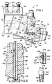
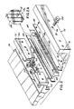
- the invention of this application is directed to an apparatus 10 for applying multiple, narrow, closely spaced beads 12 of viscous liquid to a substrate or web 14 moving beneath multiple, closely spaced, narrow slots 18 having exit openings 18a ( Figure 2A) of a nozzle assembly 16.
- This apparatus 10 is operable to direct pressurized, spaced streams of the viscous adhesive from the apparatus 10 onto the substrate or web 14. That substrate or web generally moves past the nozzle under tension and at a controlled speed, although it may be positioned on a conveyor which moves the substrate past the nozzle at a controlled speed. The movement of substrate past the nozzle is synchronized with the discharge of viscous liquid from the apparatus 10.
- the preferred embodiment of this invention comprises multiple dispensing guns 22 mounted upon a manifold block 24, which manifold block is in turn fixedly attached to a mounting block 26.
- the mounting block 26 has a pair of transverse bores 28 extending therethrough, which transverse bores 28 are adapted to receive guide rods 29 upon which the mounting block is mounted.
- the mounting block is secured in a position of adjustment on the guide rods by set screws 30 threaded into bores 32 which intersect the guide rod mounting bores 28.
- the manifold block 24 has a first longitudinally extending passageway 36 extending from the rear side 38 thereof into a transverse filter receiving bore 40.
- the opposite ends of this transverse bore 40 are closed by plugs (not shown).
- a longitudinal bore 42 which extends from the rear side 38 to a transverse bore 43.
- the bore 43 is closed at the ends by conventional plugs (not shown) and is connected via multiple parallel gun feeding bores 41 to outlet ports 49 of the manifold block. These outlet ports are aligned with inlet ports 48 of the dispensing guns so that one outlet port supplies viscous liquid to one dispensing gun 22.
- the rear of the longitudinal bore 42 is closed by a conventional threaded plug 46.
- the network of bores 36, 40, 41, 42, and 43 through the manifold block 24 described hereinabove provides a flow passageway from a liquid inlet port 44 to multiple outlet ports 49 of bores 41 for viscous liquids supplied from a pressurized source (not shown) of such viscous liquid. From the outlet ports 49 of the manifold block, the viscous liquid passes into liquid inlet ports 48 of the dispensing guns 22.
- an air flow passageway defined by a vertical bore 50, an intersecting transverse bore 52, and multiple horizontal discharge bores 54.
- the transverse bore 52 extends for the length of the manifold block and is closed at the ends by conventional plugs.
- pressurized air supplied from a source (not shown) of pressurized air through a flow control valve (not shown) is supplied from an air inlet port 56 of the manifold block 24 to discharge bores 54 of the same block.
- Each of the discharge bores 54 terminates in an outlet port 58 which opens into and communicates with an air inlet port of one of the dispersing guns 22.
- the dispensing guns 22 are conventional pneumatic operated, viscous liquid dispensing guns such as the guns disclosed in US-A-3,570,725.
- One such gun suitable for use in the apparatus 10 is manufactured by Nordson Corporation and is designated as the Nordson Corporation H-200 Dispensing Gun.
- One or more dispensing guns 22 are secured to the front side 60 of the manifold block 24 by conventional mounting screws 62. In the illustrated embodiment, there are six such guns 22 mounted atop the manifold block 24. The lower end of each of these guns 22 is mounted within a mounting bore 64 of an adaptor block 66. This adaptor block is secured by conventional connectors (not shown) to the underside of the manifold block 24.
- O-ring 65 surrounding the gun 22 and engageable with the gun mounting bore 64.
- This O-ring 65 facilitates assembly of the manifold block 24, guns 22 and adaptor block 66. To assemble these elements, the guns 22 are bolted to the manifold block 24 and the adaptor block 66 is pushed into place with the O-ring seals 65 between the guns and the bores 64 forming a seal between the gun and the liquid flow path through the adaptor block 66.
- the adaptor block has a liquid flow passage 67 extending downwardly from each of the mounting bores or recesses 64 in the adaptor block such that liquid discharged from each dispensing gun 22 is caused to flow into one of the liquid flow passages 67.
- Each of the vertical bores 67 in turn intersects a horizontally extending channel 68.
- the channel 68 in turn extends from the vertical bores 67 to the front vertical face 70 of the adaptor block 66.
- a vertical leg 72 Extending upwardly from the front end of the adaptor block, there is hung a clamping plate 74.
- This clamping plate 74 is generally L-shaped and has a vertical leg 76, as well as a horizontal leg 78.
- the vertical leg has a lip 80 which extends rearwardly and engages a front wall 82 of the adaptor block 66.
- the lower horizontal leg 78 of the clamping plate has a vertical clamping surface 84 which, as explained more fully hereinafter, contacts and functions to clamp the nozzle assembly 16 between the adaptor block 66 and the clamping plate 74.
- each of these bores receives a threaded screw 88, the end of which is threaded into a threaded recess 90 in the vertical leg 72 of the adaptor block 66.
- the screw 88 When the screw 88 is threaded into the threaded recess 90, it tends to cause the clamping plate to pivot about the lip 80 so as to clamp the nozzle assembly 16 between the forward face 70 of the adaptor block 66 and the rear face 84 of the clamping plate.
- the nozzle assembly 16 comprises a front blade 100, a rear blade 102, and a thin shim 104 sandwiched between the front blade 100 and rear blade 102.
- the blades and shim are preferably maintained as a preassembled subassembly by a pair of machine screws 92 which pass through countersunk slots 94 of the front blade and through holes 96 of the shim into threaded bores 98 of the rear blade 102.
- Both blades 100, 102 are generally rectangular in configuration and, in one preferred embodiment, are each 1.588 mm (1/16 inch) in thickness.
- the front blade has a bottom surface 106 which is located in a horizontal plane, while the rear blade 102 has a bottom surface 108 which slopes upwardly and rearwardly from the leading edge 110 of the rear blade.
- the rear blade 102 has a longitudinal slot cavity 112 which extends laterally of the direction of movement of the web 14, which direction is indicated by an arrow. Extending between the longitudinal slot cavity 112 and the horizontal channel 68 of the adaptor block 66, there are a plurality of small parallel, restrictor passageways 116 through the blade 102. As a consequence of this connection between the longitudinal slot cavity 112 of the rear blade 102 and the longitudinal slot cavity 68 in the adaptor block 66, viscous liquid which flows past the valves (not shown) of the dispensing guns flows through the bores 67, channel 68, through the parallel restrictor passageways 116 in the blade, into the longitudinal slot cavity 112.
- This longitudinal slot cavity 112 of the rear blade 102 communicates with a plurality of closely spaced, narrow vertical slots 18 in the shim 104. Consequently, viscous liquid supplied to the slot cavity 112 in the rear blade flows out of the slots 18 of the shim onto the moving web or substrate 14.
- the nozzle assembly 16 is used in its broadest sense to apply multiple, parallel, closely spaced beads of viscous liquid, as for example, molten thermoplastic adhesive material, to a substrate.
- the plurality of holes 116 in the blade 102 provide a restrictor in the flow path from the transverse channel 68 to the second transverse channel 112 in the blade 102.
- This baffle or rectrictor type distribution of viscous liquid into the second transverse channel 112 provides good uniformity of viscous liquid across the entire width of the die and provides a resistance in the system which aids in providing good, sharp cutoff of liquid flow from the nozzle assembly when the nozzle assembly is operated intermittently to provide interrupted beads over the surface of a substrate.
- the width and length of the slots 18 also contribute to the surprisingly sharp cutoff of beads when the nozzle is operated intermittently.
- the shim in order to obtain sharp cutoff, the shim must be sufficiently thin, the width of the slot must be sufficiently low, and the length of the slot sufficiently long that the flow resistance is sufficient to cut off the flow of liquid from the exit orifices of the die when the guns 22 are cut off.
- the nozzle assembly 16 of this invention is used to deposit parallel beads which provide a vertical standoff or separation between two substrates adhered together by the beads.
- the characteristics of the viscous molten thermoplastic adhesive, the operating temperature, the shim thickness, the slot width, and the substrate speed all contribute to successful application of standoff beads to a substrate.
- these parameters are chosen so as to obtain round, stable beads which substantially maintain their cross-sectional configuration when a second substrate is applied to a first substrate having the beads applied thereto. In that event, the distance between adjacent beads is dictated solely by the desired spacing of the beads in the final product.
- the viscous liquid material as well as the shim and restrictor orifices' parameters, are all selected so as to obtain full surface coverage of the interface between two substrates when a second substrate is used to compress the beads of viscous adhesive applied according to the practice of this invention. If full surface coverage is to be obtained, the thickness of the shim and the width of the slot 18 must be sufficiently great relative to the center line spacing of the slots to obtain parallel beads having sufficient viscous material volume therein to enable the beads to merge when squeezed together between the two substrates.
- the shim 104 is generally rectangular in configuration and is manufactured from brass shim stock 0.4064 mm (.016 inches) in thickness.
- the slots 18 are each 0.3048 mm (.012 inches) in width W and are spaced apart, center line to center line, a distance D of 2.54 mm (.10 inches).
- This particular embodiment of the invention is utilized to apply 61 very closely spaced thin beads of molten thermoplastic adhesive to a moving substrate 14 as that substrate passes beneath the nozzle assembly 16.
- the substrate is spaced a sufficient distance T vertically from the exit openings 18a of the nozzle assembly 16 that the beads may be applied to the substrate without the beads being sheared by contact with the rearwardmost blade 102.
- the material applied by the nozzle assembly was a molten thermoplastic material manufactured by Eastman Kodak Co. and identified as Eastman A32.
- the material was dispensed at a temperature of 187.78°C (370°F) onto a substrate travelling at 30.48 m (100 feet) per minute. This resulted in the application of a plurality of parallel, continuous beads having a substantially round, cross-sectional configuration with small flats at the interfaces of the beads with the spaced, parallel substrates adhered together by the beads.
- the nozzle assembly 16 was used to provide full film surface coverage of the surface interface between two substrates adhered together by the material dispensed from the nozzle assembly 16.
- the thermoplastic material applied by the nozzle was an adhesive manufactured by National Starch Co. and identified as their No. 342888 adhesive. This material was applied at an application temperature of 176.67°C (350°F) onto a substrate travelling at 56.39 m (185 feet) per minute.
- the shim for this application was 0.381 mm (.015 inches) in thickness, the slots were 0.4064 (.016 inches) wide, and the slots were spaced centerline to centerline 2.54 mm (.100 inches) apart. This resulted in the application of multiple, parallel beads of adhesive onto the substrate which, when the adhesive was compressed between the substrate and a second substrate, completely covered the interface between the substrates.
- shims 104 of differing thickness and having slots of differing width and spacing.
- the shim stock from which the shims are manufactured may be as little as 0.0508 mm (.002 inches) in thickness or as great as 0.254 mm (.010 inches) in thickness.
- the slots may be as wide as 0.254 mm (.010 inches) in thickness.
- viscous liquid such as molten thermoplastic adhesive
- a source of the viscous liquid is supplied under pressure from a source of the viscous liquid to the inlet port 44 of the manifold block.
- the viscous liquid passes through the manifold block to the discharge port 49 or ports, depending upon the number of dispensing guns 22 mounted upon the manifold block, and into the dispensing guns 22.
- High pressure air is supplied from a source of high pressure air (not shown) to the inlet port 56 of the manifold block. This high pressure air passes through the manifold block into the dispersing guns where it controls actuation of pneumatic cylinders contained internally of the dispensing guns.
- the beads of viscous material applied to the web 14 are illustrated as continuous beads. In many instances, though, the beads will be discontinuous or intermittent. In the event that the beads are to be intermittent, then the air supply to the inlet port 56 is controlled via a solenoid or other valve such as to control intermittent opening and closing of the valves (not shown) of the dispensing guns 22. Because the slots 18 of the nozzle assembly 16 are so small and because of the relatively high viscosity of the liquid discharged from these nozzles, the intermittent flow of viscous liquid from the nozzle assembly is characterized by surprisingly sharp, non-contact cut off upon closing of the valves of the guns 22. There is no tendency for the nozzle assembly to drip or drool viscous liquid as is characteristic of many prior art guns for applying intermittent beads to a substrate.
- a longitudinal slot cavity 212 is located in the rear surface of the front blade 200.
- a plurality of flow passages 220 extending through the rear blade 202 into a longitudinal slot cavity 221 in the rear surface of the rear blade.
- the longitudinal slot cavity 221 of the rear blade is open to passageways 222 in the shim 204 which communicate with the slot cavity 212 of the front blade.
- the slots 218 of the shim 204 are identical to the slots 18 in the first embodiment and are open at the top to the bottom of the slot cavity 212.
- FIG. 5 there is illustrated another modification of the shim which has been used to obtain very satisfactory results when employed in the nozzle assembly 16 of this invention.
- This shim 204 is identical to the shim 104 heretofore described, except that each of the slots 18b terminates at its upper end in a generally enlarged, oblong hole 205.
- this hole of each slot 18b communicates with the transverse channel 112.
- viscous liquid flowing to the channel 112 is enabled to flow through the oblong holes 205 into the slots 18b.
- the shim 204 is identical to the shim 104 heretofore described.
Landscapes
- Coating Apparatus (AREA)
- Application Of Or Painting With Fluid Materials (AREA)
Abstract
Claims (8)
- Procédé pour appliquer une série de gouttes (12), espacées et parallèles, d'un fluide visqueux sur un substrat (14) en mouvement, ledit procédé comprenant les étapes consistant à :
pomper, d'une manière synchrone au déplacement du substrat, du fluide dans un orifice d'entrée (116 ; 220) sur un côté d'une cavité (112 ; 212) en forme de fente longitudinale étroite et s'étendant transversalement par rapport au sens de déplacement du substrat (14), et
à transporter le fluide à partir dudit orifice d'entrée et le long de ladite cavité (112 ; 212) en forme de fente, transversalement par rapport au sens de déplacement du substrat (14);
caractérisé en ce qu'il comprend les étapes consistant à :
former une pluralité de rainures (18 ; 218) parallèles et espacées, dans une lamelle plane (104 ; 204), lesdites rainures s'étendant d'un côté à l'autre de la lamelle (104 ; 204), et étant ouvertes sur une arête (110) de ladite lamelle plane (104 ; 204), et lesdites rainures (18 ; 218) étant fermées sur l'arête opposée de la lamelle plane (104 ; 204),
placer ladite lamelle plane (104 ; 204) en juxtaposition entre des surfaces planes de deux lames (100, 102 ; 200, 202), au moins l'une de ces lames comportant ladite cavité (112 ; 212) en forme de fente longitudinale étroite, qui communique avec ladite pluralité de rainures (18 ; 218) de ladite lamelle plane (104; 204),
injecter le fluide de la cavité (112 ; 212) en forme de fente, transversalement, vers des parties supérieures desdites rainures (18 ; 218) parallèles et espacées, lesdites rainures présentant des ouvertures de sortie (18a) inférieures, dirigées vers le substrat (14), lesdites rainures (18 ; 218) parallèles et espacées étant espacées les unes des autres transversalement par rapport au sens de déplacement dudit substrat (14);
et
placer lesdites ouvertures de sortie (18a) au-dessus dudit substrat (14) de manière à ce que les gouttes (12) de fluide visqueux sortant desdites ouvertures de sortie (18a) ne soient pas coupées, lorsqu'elles sortent desdites ouvertures de sortie (18a). - Procédé selon la revendication 1, dans lequel lesdites rainures (18 ; 218) parallèles et espacées, sont espacées les unes des autres transversalement par rapport au sens de déplacement dudit substrat (14) et lesdites ouvertures de sortie (18a) sont d'une largeur inférieure ou égale à 2,54 mm (0,10 pouces) et d'une profondeur inférieure ou égale à 2,54 mm (0,10 pouces).
- Procédé pour appliquer plusieurs gouttes (12) parallèles et espacées, d'un fluide visqueux sur un substrat en mouvement (14), ledit procédé comprenant les étapes consistant à :
pomper du fluide d'une manière synchrone au déplacement du substrat, dans un orifice d'entrée (220) sur un côté d'une première cavité (221) en forme de fente longitudinale étroite, cette première cavité en forme de fente s'étendant transversalement par rapport au sens de déplacement du substrat (14), et
à transporter le fluide à partir dudit orifice d'entrée (220), et le long de ladite cavité (221) en forme de fente, transversalement par rapport au sens de déplacement du substrat (14);
caractérisé en ce qu'il comprend les étapes consistant à :
former une pluralité de rainures (18 ; 218) parallèles et espacées dans une lamelle plane (204), lesdites rainures s'étendant d'un côté à l'autre de la lamelle (204), et étant ouvertes sur une arête de ladite lamelle plane (204), lesdites fentes (218) étant fermées sur l'arête opposée de la lamelle plane (204),
placer ladite lamelle (204) en juxtaposition entre des surfaces planes de deux lames (200; 202), au moins l'une de ces lames comportant ladite première cavité (221) en forme de fente, qui communique avec ladite pluralité de rainures (218) de ladite lamelle plane (204),
injecter le fluide transporté dans le sens longitudinal dans la première cavité (221) en forme de fente, transversalement via une pluralité d'orifices d'étranglement (222) espacés dans le sens longitudinal, dans une deuxième cavité (212) en forme de fente longitudinale étroite,
transporter le fluide depuis lesdits orifices d'étranglement (222), dans le sens longitudinal, le long de ladite deuxième cavité (212) en forme de fente,
injecter le fluide transporté dans le sens longitudinal dans la deuxième cavité (212) en forme de fente, transversalement dans des parties supérieures des rainures (218) parallèles et espacées, lesdites rainures présentant des ouvertures de sortie inférieures, dirigées vers le substrat (14), lesdites rainures (218) parallèles et espacées étant espacées les unes des autres transversalement par rapport au sens de déplacement dudit substrat (14), et
à placer lesdites ouvertures de sortie au-dessus dudit substrat (14) de manière à ce que les gouttes (12) de fluide visqueux sortant desdites ouvertures de sortie ne soient pas coupées, lorsqu'elles sortent desdites ouvertures de sortie. - Procédé selon la revendication 3, comprenant en outre l'étape consistant à
appliquer lesdites gouttes (12) sur ledit substrat (14) selon des dimensions et une configuration fonction des propriétés du fluide visqueux, de manière à ce que les gouttes appliquées sur ledit substrat forment un film d'isolation entre ledit substrat et un deuxième substrat placé par la suite au-dessus desdites gouttes. - Procédé selon la revendication 3, comprenant en outre la compression desdites gouttes (12) entre ledit substrat et un deuxième substrat, lesdites gouttes étant d'une hauteur et d'une largeur par rapport à l'espacement des gouttes de manière à couvrir complètement la surface du substrat (12) lorsqu'elles sont comprimées entre ledit substrat et ledit deuxième substrat.
- Appareil (10) pour appliquer plusieurs gouttes (12) parallèles et espacées de fluide visqueux sur un substrat (14) en mouvement, ledit appareil comprenant :
un moyen formant support dudit substrat (14),
caractérisé par
une première lame (102 ; 202) présentant un côté formant fond et une cavité (112 ; 221) en forme de fente longitudinale étroite, sur un autre côté de celle-ci, ladite lame présentant des moyens (116 ; 221) formant orifices d'entrée, ouvrant sur ladite cavité (112 ; 221) en forme de fente, ladite cavité en forme de fente s'étendant transversalement par rapport au sens de déplacement du substrat (14),
une deuxième lame (100 ; 200) présentant un côté formant fond et une surface sensiblement plane sur l'autre côté de celle-ci, et
une lamelle (104 ; 204) prise en sandwich entre ledit autre côté de ladite première lame (102 ; 202) et ledit autre côté de ladite deuxième lame (100; 200), ladite lamelle (104 ; 204) présentant une pluralité de rainures (18; 218) parallèles et espacées, ouvertes sur une arête de ladite lamelle (104 ; 204) et en communication fluidique avec ladite cavité (112 ; 212) en forme de fente de ladite première lame (102 ; 202), ladite arête de ladite lamelle (104 ; 204) étant dirigée vers le substrat (14) mais espacée de celui-ci, lesdites rainures (18 ; 218) parallèles et espacées de ladite lamelle (104; 204) étant espacées les unes des autres transversalement par rapport au sens de déplacement du substrat (14) et dans lequel lesdits côtés formant fonds desdites première et deuxième lames (102, 100 ; 202, 200) et ladite arête de ladite lamelle (104 ; 204) sont espacés au-dessus dudit moyen formant support dudit substrat (14) de manière telle que les gouttes (12) de fluide visqueux sortant desdites rainures espacées (18) ne sont pas coupées par l'une desdites lames (102, 100 ; 202, 200) lorsqu'elles sortent desdites ouvertures de sortie (18a). - Appareil selon la revendication 6, dans lequel ledit moyen formant orifices d'entrée (116; 221) s'ouvrant sur ladite cavité (112, 212) en forme de fente de ladite première lame (102 ; 202) comprend une pluralité de petits orifices d'entrée d'étranglement espacés sur la longueur de ladite cavité (112; 212) en forme de fente.
- Appareil selon la revendication 7, dans lequel lesdites rainures (18; 218) espacées de ladite lamelle (104 ; 204) sont d'une largeur au plus égale à 2,54 mm (0,10 pouces) environ et ladite lamelle (104; 204) est d'une épaisseur au plus égale à 2,54 mm (0,10 pouces) environ.
Applications Claiming Priority (3)
| Application Number | Priority Date | Filing Date | Title |
|---|---|---|---|
| US76202 | 1987-07-21 | ||
| US07/076,202 US4774109A (en) | 1987-07-21 | 1987-07-21 | Method and apparatus for applying narrow, closely spaced beads of viscous liquid to a substrate |
| PCT/US1988/002231 WO1989000459A1 (fr) | 1987-07-21 | 1988-06-29 | Procede et appareil d'application de perles etroites, a espacement serre de liquides visqueux sur un substrat |
Publications (3)
| Publication Number | Publication Date |
|---|---|
| EP0368914A1 EP0368914A1 (fr) | 1990-05-23 |
| EP0368914A4 EP0368914A4 (en) | 1991-11-21 |
| EP0368914B1 true EP0368914B1 (fr) | 1994-06-08 |
Family
ID=22130557
Family Applications (1)
| Application Number | Title | Priority Date | Filing Date |
|---|---|---|---|
| EP88906812A Expired - Lifetime EP0368914B1 (fr) | 1987-07-21 | 1988-06-29 | Procede et appareil d'application de perles etroites, a espacement serre de liquides visqueux sur un substrat |
Country Status (7)
| Country | Link |
|---|---|
| US (1) | US4774109A (fr) |
| EP (1) | EP0368914B1 (fr) |
| JP (1) | JPH02504235A (fr) |
| AU (1) | AU598437B2 (fr) |
| CA (1) | CA1291679C (fr) |
| DE (1) | DE3850111T2 (fr) |
| WO (1) | WO1989000459A1 (fr) |
Families Citing this family (71)
| Publication number | Priority date | Publication date | Assignee | Title |
|---|---|---|---|---|
| DE3804856A1 (de) * | 1988-02-17 | 1989-08-31 | Macon Gmbh Klebstoff Auftragsg | Vorrichtung zum flaechigen auftragen von leim oder dergleichen |
| DE8812493U1 (de) * | 1988-10-04 | 1990-02-01 | Nordson Corp., Westlake, Ohio | Schlitzdüse |
| US5024709A (en) * | 1990-01-22 | 1991-06-18 | Slautterback Corporation | Contact-free method of forming sift-proof seals |
| US4969601A (en) * | 1989-05-01 | 1990-11-13 | Slautterback Corporation | Directly thermally coupled adhesive dispenser |
| KR100230753B1 (ko) * | 1991-01-23 | 1999-11-15 | 도꾜 일렉트론 큐슈리미티드 | 액도포 시스템 |
| US5334247A (en) * | 1991-07-25 | 1994-08-02 | Eastman Kodak Company | Coater design for low flowrate coating applications |
| CA2081499A1 (fr) * | 1991-11-01 | 1993-05-02 | Wesley Fort | Methode et dispositif de distribution de liquide visqueux par gouttes multiples |
| US5294258A (en) * | 1992-04-08 | 1994-03-15 | Nordson Corporation | Apparatus for producing an integral adhesive matrix |
| DE69314343T2 (de) * | 1992-07-08 | 1998-03-26 | Nordson Corp | Vorrichtung und verfahren zum aufbringen von schaumbeschichtungen |
| DE69317706T2 (de) * | 1992-07-08 | 1998-07-30 | Nordson Corp | Apparat und Verfahren zum Auftrag von diskontinuierlichen Beschichtungen |
| US5418009A (en) * | 1992-07-08 | 1995-05-23 | Nordson Corporation | Apparatus and methods for intermittently applying discrete adhesive coatings |
| CA2098784A1 (fr) * | 1992-07-08 | 1994-01-09 | Bentley Boger | Installation et methodes pour deposer un revetement conforme sur des plaquettes de circuits electroniques |
| US5421921A (en) * | 1992-07-08 | 1995-06-06 | Nordson Corporation | Segmented slot die for air spray of fibers |
| US5354378A (en) * | 1992-07-08 | 1994-10-11 | Nordson Corporation | Slot nozzle apparatus for applying coatings to bottles |
| CA2095555A1 (fr) * | 1992-12-16 | 1994-06-17 | Robert L. Popp | Appareil et methodes de controle selectif de pulverisation d'un liquide |
| US5389151A (en) * | 1993-03-15 | 1995-02-14 | Nordson Corporation | Interchangeable contact/non-contact dispensing system |
| US5458291A (en) * | 1994-03-16 | 1995-10-17 | Nordson Corporation | Fluid applicator with a noncontacting die set |
| US5639305A (en) * | 1994-04-29 | 1997-06-17 | Minnesota Mining And Manufacturing Company | Die coating method and apparatus |
| JP3777405B2 (ja) * | 1994-04-29 | 2006-05-24 | スリーエム カンパニー | 改良されたダイリップを用いたダイ塗布装置 |
| US5741549A (en) * | 1994-04-29 | 1998-04-21 | Maier; Gary W. | Slide die coating method and apparatus with improved die lip |
| BR9507569A (pt) * | 1994-04-29 | 1997-08-05 | Minnesota Mining & Mfg | Aparelho e processo de revestimento com matriz |
| US5759274A (en) * | 1994-04-29 | 1998-06-02 | Minnesota Mining And Manufacturing Company | Die coating apparatus with surface covering |
| US5556471A (en) * | 1994-05-17 | 1996-09-17 | Nordson Corporation | Method and apparatus for dispensing foam materials |
| KR100369571B1 (ko) * | 1994-12-28 | 2003-04-10 | 도레이 가부시끼가이샤 | 도포방법및도포장치 |
| US6037009A (en) * | 1995-04-14 | 2000-03-14 | Kimberly-Clark Worldwide, Inc. | Method for spraying adhesive |
| US5618347A (en) * | 1995-04-14 | 1997-04-08 | Kimberly-Clark Corporation | Apparatus for spraying adhesive |
| EP0761877A3 (fr) * | 1995-09-06 | 1997-06-25 | Voith Sulzer Papiermasch Gmbh | Dispositif d'application directe ou indirecte de matériau fluide ou pâteux sur une bande en mouvement, en particulier de papier ou carton |
| JP3200763B2 (ja) | 1997-02-04 | 2001-08-20 | 株式会社ヒラノテクシード | 両面塗工型塗工装置 |
| US6001178A (en) * | 1997-05-13 | 1999-12-14 | Nordson Corporation | Method and apparatus for applying uniform layers of adhesive to contoured surfaces of a substrate |
| US20030200923A1 (en) * | 2002-04-30 | 2003-10-30 | Kimberly-Clark Worldwide, Inc. | Core oil and fragrance addition apparatus and method |
| US7591903B2 (en) * | 2002-08-13 | 2009-09-22 | 3M Innovative Properties Company | Die having multiple orifice slot |
| DE50302494D1 (de) * | 2003-04-19 | 2006-04-27 | Frech Oskar Gmbh & Co Kg | Sprühkopf für ein Sprühwerkzeug |
| DE10357231B4 (de) * | 2003-12-08 | 2012-12-27 | Synflex Elektro Gmbh & Co. Kg | Streifenbeschichtetes Elektroklebeband und Verfahren zu dessen Herstellung |
| US20050268845A1 (en) * | 2004-06-03 | 2005-12-08 | Nordson Corporation | Apparatus and nozzle plate for dispensing liquid material |
| US20050271806A1 (en) * | 2004-06-03 | 2005-12-08 | Nordson Corporation | Dispenser and method for non-contact dispensing of adhesive |
| DE102004058542A1 (de) * | 2004-12-03 | 2006-06-08 | Nordson Corporation, Westlake | Rotationsauftragskopf und Etikettieranlage zum Aufbringen von Etiketten |
| US20060258249A1 (en) * | 2005-05-11 | 2006-11-16 | Fairbanks Jason S | Elastic laminates and process for producing same |
| US7771556B2 (en) * | 2005-07-01 | 2010-08-10 | Nordson Corporation | Apparatus and process to apply adhesive during labeling operations |
| WO2007106390A2 (fr) | 2006-03-10 | 2007-09-20 | Amesbury Group, Inc | Systemes et procedes de fabrication de profiles d'etancheite renforces |
| DE202006016674U1 (de) * | 2006-10-27 | 2007-02-22 | Nordson Corporation, Westlake | Auftragsvorrichtung zum Auftragen von flüssigem Material |
| US7798434B2 (en) | 2006-12-13 | 2010-09-21 | Nordson Corporation | Multi-plate nozzle and method for dispensing random pattern of adhesive filaments |
| USD550261S1 (en) | 2006-12-13 | 2007-09-04 | Nordson Corporation | Adhesive dispensing nozzle |
| US10137472B2 (en) * | 2007-04-06 | 2018-11-27 | Illinois Tool Works Inc. | Dual pattern shim assembly for use in conjunction with hot melt adhesive dispensing systems |
| JP5587531B2 (ja) * | 2007-07-19 | 2014-09-10 | ノードソン コーポレーション | スロットノズル組立体、スロットコートガン、及び幅広の帯状に発泡性溶融体を押し出す方法 |
| US20090162595A1 (en) * | 2007-12-19 | 2009-06-25 | Chan Ko | Striped adhesive construction and method and die for making same |
| US8171973B2 (en) * | 2008-01-29 | 2012-05-08 | Nordson Corporation | Nozzle and related apparatus and method for dispensing molten thermoplastic material |
| USD588617S1 (en) | 2008-04-14 | 2009-03-17 | Nordson Corporation | Nozzle assembly |
| US8074902B2 (en) * | 2008-04-14 | 2011-12-13 | Nordson Corporation | Nozzle and method for dispensing random pattern of adhesive filaments |
| EP2213380B1 (fr) | 2009-01-22 | 2012-01-18 | Coroplast Fritz Müller GmbH & Co. KG | Outil d'application et procédé de revêtement en forme de bande d'un support en forme de bande |
| JP5383328B2 (ja) * | 2009-06-08 | 2014-01-08 | ユニ・チャーム株式会社 | 接着剤用コータのノズル |
| US8551562B2 (en) | 2009-07-17 | 2013-10-08 | Illnois Tool Works Inc. | Method for metering hot melt adhesives with variable adhesive volumes |
| JP5607326B2 (ja) * | 2009-08-06 | 2014-10-15 | ノードソン コーポレーション | 塗工ノズル、塗工方法、及び内容積制御弁 |
| US9573159B2 (en) * | 2009-08-31 | 2017-02-21 | Illinois Tool Works, Inc. | Metering system for simultaneously dispensing two different adhesives from a single metering device or applicator onto a common substrate |
| US9718081B2 (en) * | 2009-08-31 | 2017-08-01 | Illinois Tool Works Inc. | Metering system for simultaneously dispensing two different adhesives from a single metering device or applicator onto a common substrate |
| US8752501B2 (en) | 2010-07-29 | 2014-06-17 | Corning Incorporated | Systems and methods for dispensing a fluid |
| US10371468B2 (en) | 2011-11-30 | 2019-08-06 | Palo Alto Research Center Incorporated | Co-extruded microchannel heat pipes |
| US9120190B2 (en) | 2011-11-30 | 2015-09-01 | Palo Alto Research Center Incorporated | Co-extruded microchannel heat pipes |
| US8875653B2 (en) * | 2012-02-10 | 2014-11-04 | Palo Alto Research Center Incorporated | Micro-extrusion printhead with offset orifices for generating gridlines on non-square substrates |
| AU2013281097B2 (en) | 2012-06-25 | 2016-06-02 | 3M Innovative Properties Company | Devices for coating contoured surfaces |
| US9700912B2 (en) | 2012-06-27 | 2017-07-11 | William K. Leonard | Fluid transport media |
| EP2679314B1 (fr) * | 2012-06-29 | 2018-03-28 | National Taiwan University | Module de revêtement |
| TWI496625B (zh) | 2012-06-29 | 2015-08-21 | Univ Nat Taiwan | 塗佈模組 |
| BR112016028062B1 (pt) | 2014-06-13 | 2021-12-14 | Essity Hygiene And Health Aktiebolag | Unidade de empacotamento para artigos de higiene e método de formação de uma unidade de empacotamento para artigos de higiene |
| CN106456418A (zh) | 2014-06-13 | 2017-02-22 | Sca卫生用品公司 | 具有改良密封性和使用者提示装置的包装单元及用于制造此包装单元的方法 |
| US9834355B2 (en) | 2014-06-13 | 2017-12-05 | Sca Hygiene Products Ab | Packaging unit having improved sealing, and a method for forming such a packaging unit |
| RU2644113C1 (ru) | 2014-06-13 | 2018-02-07 | Ска Хайджин Продактс Аб | Способ образования обертывающего листа, имеющего улучшенную герметизирующую способность |
| US10086989B2 (en) | 2014-06-13 | 2018-10-02 | Sca Hygiene Products Ab | Packaging unit for hygiene articles and a method of forming a packaging unit |
| US10329834B2 (en) | 2015-02-13 | 2019-06-25 | Amesbury Group, Inc. | Low compression-force TPE weatherseals |
| JP7593741B2 (ja) | 2020-03-26 | 2024-12-03 | ノードソン コーポレーション | ノズル、接着剤塗布ヘッド、接着剤塗布装置及びおむつ製造方法 |
| US11484905B1 (en) * | 2021-04-30 | 2022-11-01 | Nordson Corporation | Spray nozzle clamp |
| DE102024128846A1 (de) * | 2024-10-07 | 2026-04-09 | HighLine Technology GmbH | Druckkopf und dessen Verwendung |
Family Cites Families (19)
| Publication number | Priority date | Publication date | Assignee | Title |
|---|---|---|---|---|
| US2916012A (en) * | 1957-02-19 | 1959-12-08 | Raytheon Co | Line ruling devices and method |
| US3106481A (en) * | 1959-08-24 | 1963-10-08 | Sorg Adam | Method of coating tea bag paper to render it heat-sealable |
| US3302611A (en) * | 1964-06-26 | 1967-02-07 | Riegel Textile Corp | Striping apparatus |
| NL157542B (nl) * | 1966-12-29 | 1978-08-15 | Hoechst Ag | Mondstuk met brede spleet. |
| US3570725A (en) * | 1968-11-15 | 1971-03-16 | Nordson Corp | Applicator having a fixed module with static parts and a removable module with moving parts |
| US3849241A (en) * | 1968-12-23 | 1974-11-19 | Exxon Research Engineering Co | Non-woven mats by melt blowing |
| US3690518A (en) * | 1970-11-13 | 1972-09-12 | Nordson Corp | Modular applicator system |
| US3825379A (en) * | 1972-04-10 | 1974-07-23 | Exxon Research Engineering Co | Melt-blowing die using capillary tubes |
| US3840158A (en) * | 1972-10-17 | 1974-10-08 | Nordson Corp | Modular applicator system |
| US3890926A (en) * | 1974-07-25 | 1975-06-24 | Riegel Textile Corp | Apparatus for intermittently applying deposits of adhesive onto a moving web of material |
| GB1490616A (en) * | 1975-04-10 | 1977-11-02 | Molins Ltd | Liquid-applicator nozzles |
| EP0003860B1 (fr) * | 1978-03-01 | 1982-03-24 | Agfa-Gevaert N.V. | Méthode pour le revêtement par rideau d'une nappe avec des couches photographiques multiples superposées |
| US4220114A (en) * | 1978-09-22 | 1980-09-02 | Radowicz Richard D | Applicator head for adhesive application system |
| US4476165A (en) * | 1982-06-07 | 1984-10-09 | Acumeter Laboratories, Inc. | Method of and apparatus for multi-layer viscous fluid deposition such as for the application of adhesives and the like |
| US4550681A (en) * | 1982-10-07 | 1985-11-05 | Johannes Zimmer | Applicator for uniformly distributing a flowable material over a receiving surface |
| EP0142583B1 (fr) * | 1983-11-14 | 1987-05-20 | Kyowa Denki Kagaku K.K. | Procédé et appareil pour enduire les surfaces de récipients d'une matière de revêtement |
| JPS60143866A (ja) * | 1983-12-29 | 1985-07-30 | Konishiroku Photo Ind Co Ltd | 塗布方法及びその装置 |
| US4557958A (en) * | 1984-07-03 | 1985-12-10 | Standard Oil Company (Indiana) | Non-fraying, breathable fabric suitable for use as a cotton bale cover and bag fabric, apparatus and method for making the same |
| US4679711A (en) * | 1985-09-11 | 1987-07-14 | Nordson Corporation | Multi-orifice zero cavity nozzle dispenser |
-
1987
- 1987-07-21 US US07/076,202 patent/US4774109A/en not_active Expired - Fee Related
-
1988
- 1988-05-31 CA CA000568184A patent/CA1291679C/fr not_active Expired - Lifetime
- 1988-06-29 WO PCT/US1988/002231 patent/WO1989000459A1/fr not_active Ceased
- 1988-06-29 AU AU22595/88A patent/AU598437B2/en not_active Ceased
- 1988-06-29 JP JP63506817A patent/JPH02504235A/ja active Pending
- 1988-06-29 DE DE3850111T patent/DE3850111T2/de not_active Expired - Fee Related
- 1988-06-29 EP EP88906812A patent/EP0368914B1/fr not_active Expired - Lifetime
Also Published As
| Publication number | Publication date |
|---|---|
| EP0368914A1 (fr) | 1990-05-23 |
| JPH02504235A (ja) | 1990-12-06 |
| CA1291679C (fr) | 1991-11-05 |
| DE3850111D1 (de) | 1994-07-14 |
| AU598437B2 (en) | 1990-06-21 |
| DE3850111T2 (de) | 1995-01-19 |
| EP0368914A4 (en) | 1991-11-21 |
| WO1989000459A1 (fr) | 1989-01-26 |
| AU2259588A (en) | 1989-02-13 |
| US4774109A (en) | 1988-09-27 |
Similar Documents
| Publication | Publication Date | Title |
|---|---|---|
| EP0368914B1 (fr) | Procede et appareil d'application de perles etroites, a espacement serre de liquides visqueux sur un substrat | |
| US4844004A (en) | Method and apparatus for applying narrow, closely spaced beads of viscous liquid to a substrate | |
| US5429840A (en) | Apparatus and methods for applying discrete foam coatings | |
| US5335825A (en) | Method and apparatus for dispensing multiple beads of viscous liquid | |
| KR860001636B1 (ko) | 블레이드 형식의 파운틴 로우터와 그 방법 | |
| US5683036A (en) | Apparatus for applying discrete coatings | |
| US5421921A (en) | Segmented slot die for air spray of fibers | |
| EP2441528B1 (fr) | Buse pour dispositif de revêtement d'adhésif | |
| US5769947A (en) | Applicator for adhesive and corresponding nozzle plate | |
| EP0578119A1 (fr) | Appareil et méthodes pour l'application par intervalles de revêtements adhésifs | |
| EP0578469A2 (fr) | Améliorations relatives dans ou à l'application de revêtements | |
| US3886898A (en) | Multiple, contiguous stripe, extrusion coating apparatus | |
| EP0951364B1 (fr) | Filiere auto-scellante a buse en forme de fente | |
| JP2022171588A (ja) | 接着剤塗布器のスロットノズル | |
| US20080286475A1 (en) | Process and related apparatus for block coating | |
| JP2000506778A (ja) | 材料の可動ウェブへ流体を塗布する装置及び方法 | |
| WO2000050215A1 (fr) | Procede d'extrusion d'une couche continue | |
| US7556692B2 (en) | Device for coating a continuous web of material | |
| JPH05309310A (ja) | ホットメルト接着剤塗布装置 | |
| KR100324050B1 (ko) | 표면에 코팅액을 도포하는 장치 및 그 방법 | |
| US6444269B1 (en) | Apparatus and method for coating sheet or strip articles | |
| JP2992812B2 (ja) | ホットメルト接着剤塗布装置およびホットメルト接着剤塗布方法 | |
| MXPA01008607A (en) | Extrusion apparatus for extruding continuous layer of extrudate |
Legal Events
| Date | Code | Title | Description |
|---|---|---|---|
| PUAI | Public reference made under article 153(3) epc to a published international application that has entered the european phase |
Free format text: ORIGINAL CODE: 0009012 |
|
| 17P | Request for examination filed |
Effective date: 19891220 |
|
| AK | Designated contracting states |
Kind code of ref document: A1 Designated state(s): BE DE FR GB IT |
|
| A4 | Supplementary search report drawn up and despatched |
Effective date: 19910930 |
|
| AK | Designated contracting states |
Kind code of ref document: A4 Designated state(s): BE DE FR GB IT |
|
| 17Q | First examination report despatched |
Effective date: 19930608 |
|
| GRAA | (expected) grant |
Free format text: ORIGINAL CODE: 0009210 |
|
| AK | Designated contracting states |
Kind code of ref document: B1 Designated state(s): BE DE FR GB IT |
|
| REF | Corresponds to: |
Ref document number: 3850111 Country of ref document: DE Date of ref document: 19940714 |
|
| ITF | It: translation for a ep patent filed | ||
| ET | Fr: translation filed | ||
| PLBE | No opposition filed within time limit |
Free format text: ORIGINAL CODE: 0009261 |
|
| STAA | Information on the status of an ep patent application or granted ep patent |
Free format text: STATUS: NO OPPOSITION FILED WITHIN TIME LIMIT |
|
| PGFP | Annual fee paid to national office [announced via postgrant information from national office to epo] |
Ref country code: FR Payment date: 19950510 Year of fee payment: 8 |
|
| PGFP | Annual fee paid to national office [announced via postgrant information from national office to epo] |
Ref country code: GB Payment date: 19950512 Year of fee payment: 8 |
|
| PGFP | Annual fee paid to national office [announced via postgrant information from national office to epo] |
Ref country code: DE Payment date: 19950529 Year of fee payment: 8 |
|
| PGFP | Annual fee paid to national office [announced via postgrant information from national office to epo] |
Ref country code: BE Payment date: 19950530 Year of fee payment: 8 |
|
| 26N | No opposition filed | ||
| PG25 | Lapsed in a contracting state [announced via postgrant information from national office to epo] |
Ref country code: GB Effective date: 19960629 |
|
| PG25 | Lapsed in a contracting state [announced via postgrant information from national office to epo] |
Ref country code: BE Effective date: 19960630 |
|
| BERE | Be: lapsed |
Owner name: NORDSON CORP. Effective date: 19960630 |
|
| GBPC | Gb: european patent ceased through non-payment of renewal fee |
Effective date: 19960629 |
|
| PG25 | Lapsed in a contracting state [announced via postgrant information from national office to epo] |
Ref country code: FR Effective date: 19970228 |
|
| PG25 | Lapsed in a contracting state [announced via postgrant information from national office to epo] |
Ref country code: DE Effective date: 19970301 |
|
| REG | Reference to a national code |
Ref country code: FR Ref legal event code: ST |
|
| PG25 | Lapsed in a contracting state [announced via postgrant information from national office to epo] |
Ref country code: IT Free format text: LAPSE BECAUSE OF NON-PAYMENT OF DUE FEES;WARNING: LAPSES OF ITALIAN PATENTS WITH EFFECTIVE DATE BEFORE 2007 MAY HAVE OCCURRED AT ANY TIME BEFORE 2007. THE CORRECT EFFECTIVE DATE MAY BE DIFFERENT FROM THE ONE RECORDED. Effective date: 20050629 |