EP0368922B1 - Selecteur de vitesses a servocommande - Google Patents
Selecteur de vitesses a servocommande Download PDFInfo
- Publication number
- EP0368922B1 EP0368922B1 EP19880907056 EP88907056A EP0368922B1 EP 0368922 B1 EP0368922 B1 EP 0368922B1 EP 19880907056 EP19880907056 EP 19880907056 EP 88907056 A EP88907056 A EP 88907056A EP 0368922 B1 EP0368922 B1 EP 0368922B1
- Authority
- EP
- European Patent Office
- Prior art keywords
- signal
- clutch pedal
- clutch
- pressure
- electromagnet
- Prior art date
- Legal status (The legal status is an assumption and is not a legal conclusion. Google has not performed a legal analysis and makes no representation as to the accuracy of the status listed.)
- Expired - Lifetime
Links
Images

Classifications
-
- G—PHYSICS
- G05—CONTROLLING; REGULATING
- G05G—CONTROL DEVICES OR SYSTEMS INSOFAR AS CHARACTERISED BY MECHANICAL FEATURES ONLY
- G05G1/00—Controlling members, e.g. knobs or handles; Assemblies or arrangements thereof; Indicating position of controlling members
- G05G1/30—Controlling members actuated by foot
- G05G1/46—Means, e.g. links, for connecting the pedal to the controlled unit
-
- F—MECHANICAL ENGINEERING; LIGHTING; HEATING; WEAPONS; BLASTING
- F16—ENGINEERING ELEMENTS AND UNITS; GENERAL MEASURES FOR PRODUCING AND MAINTAINING EFFECTIVE FUNCTIONING OF MACHINES OR INSTALLATIONS; THERMAL INSULATION IN GENERAL
- F16H—GEARING
- F16H59/00—Control inputs to control units of change-speed- or reversing-gearings for conveying rotary motion
- F16H59/50—Inputs being a function of the status of the machine, e.g. position of doors or safety belts
- F16H59/56—Inputs being a function of the status of the machine, e.g. position of doors or safety belts dependent on signals from the main clutch
-
- F—MECHANICAL ENGINEERING; LIGHTING; HEATING; WEAPONS; BLASTING
- F16—ENGINEERING ELEMENTS AND UNITS; GENERAL MEASURES FOR PRODUCING AND MAINTAINING EFFECTIVE FUNCTIONING OF MACHINES OR INSTALLATIONS; THERMAL INSULATION IN GENERAL
- F16H—GEARING
- F16H63/00—Control outputs from the control unit to change-speed- or reversing-gearings for conveying rotary motion or to other devices than the final output mechanism
- F16H63/40—Control outputs from the control unit to change-speed- or reversing-gearings for conveying rotary motion or to other devices than the final output mechanism comprising signals other than signals for actuating the final output mechanisms
-
- B—PERFORMING OPERATIONS; TRANSPORTING
- B60—VEHICLES IN GENERAL
- B60W—CONJOINT CONTROL OF VEHICLE SUB-UNITS OF DIFFERENT TYPE OR DIFFERENT FUNCTION; CONTROL SYSTEMS SPECIALLY ADAPTED FOR HYBRID VEHICLES; ROAD VEHICLE DRIVE CONTROL SYSTEMS FOR PURPOSES NOT RELATED TO THE CONTROL OF A PARTICULAR SUB-UNIT
- B60W50/00—Details of control systems for road vehicle drive control not related to the control of a particular sub-unit, e.g. process diagnostic or vehicle driver interfaces
- B60W50/08—Interaction between the driver and the control system
- B60W50/14—Means for informing the driver, warning the driver or prompting a driver intervention
- B60W2050/143—Alarm means
-
- B—PERFORMING OPERATIONS; TRANSPORTING
- B60—VEHICLES IN GENERAL
- B60W—CONJOINT CONTROL OF VEHICLE SUB-UNITS OF DIFFERENT TYPE OR DIFFERENT FUNCTION; CONTROL SYSTEMS SPECIALLY ADAPTED FOR HYBRID VEHICLES; ROAD VEHICLE DRIVE CONTROL SYSTEMS FOR PURPOSES NOT RELATED TO THE CONTROL OF A PARTICULAR SUB-UNIT
- B60W2540/00—Input parameters relating to occupants
- B60W2540/14—Clutch pedal position
-
- F—MECHANICAL ENGINEERING; LIGHTING; HEATING; WEAPONS; BLASTING
- F16—ENGINEERING ELEMENTS AND UNITS; GENERAL MEASURES FOR PRODUCING AND MAINTAINING EFFECTIVE FUNCTIONING OF MACHINES OR INSTALLATIONS; THERMAL INSULATION IN GENERAL
- F16H—GEARING
- F16H59/00—Control inputs to control units of change-speed- or reversing-gearings for conveying rotary motion
- F16H2059/006—Overriding automatic control
-
- F—MECHANICAL ENGINEERING; LIGHTING; HEATING; WEAPONS; BLASTING
- F16—ENGINEERING ELEMENTS AND UNITS; GENERAL MEASURES FOR PRODUCING AND MAINTAINING EFFECTIVE FUNCTIONING OF MACHINES OR INSTALLATIONS; THERMAL INSULATION IN GENERAL
- F16H—GEARING
- F16H59/00—Control inputs to control units of change-speed- or reversing-gearings for conveying rotary motion
- F16H59/02—Selector apparatus
- F16H2059/0239—Up- and down-shift or range or mode selection by repeated movement
-
- F—MECHANICAL ENGINEERING; LIGHTING; HEATING; WEAPONS; BLASTING
- F16—ENGINEERING ELEMENTS AND UNITS; GENERAL MEASURES FOR PRODUCING AND MAINTAINING EFFECTIVE FUNCTIONING OF MACHINES OR INSTALLATIONS; THERMAL INSULATION IN GENERAL
- F16H—GEARING
- F16H59/00—Control inputs to control units of change-speed- or reversing-gearings for conveying rotary motion
- F16H59/68—Inputs being a function of gearing status
Definitions
- connection of the feedback for the gearshift carried out in the gearbox with the lever of the gear switch does give the driver information that comes closest to that of a gearshift device with a shift linkage.
- it is tied to the lever of the gear switch or to a comparable gear shift lever, as the examples shown show, and requires a very large amount of construction.
- An acoustic signal is easy to implement, but is not very suitable as information for the driver, and such signals are annoying with a high switching frequency.
- acoustic signals are used as warning signals, while the feedback of the shift in the transmission for a shift carried out by an assistant is a completely normal but necessary information.
- the implementation is possible electrically in connection with, for example, an electromagnet, but also electro-pneumatically or electro-hydraulically in connection with a solenoid valve.
- the electromagnet can be connected to the clutch pedal via a short linkage, but can also be arranged directly in the pedal plate of the clutch pedal.
- the strength of the haptic - tactile - signal can be easily determined using a potentiometer that regulates the voltage, adjustable.
- the arrangement of a signal transmitter in the form of an electromagnet in connection with a pressure piston, which acts on the pressure line between a master piston-cylinder unit on the clutch pedal and a slave piston-cylinder unit on the clutch, is particularly favorable.
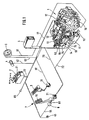
- a motor vehicle transmission 1 with a valve block 11 and three shift cylinders 12, 13, 14 for, for example, three alleys of gears is shown.
- pressure medium for example compressed air
- a gear switch 2 with travel range selector 21, an accelerator pedal 3 with load sensor 31 and an optical gear indicator 4 are connected to an electronic control unit 5 via electrical lines 22, 32, 42.
- an electronic tachograph 6 is connected via lines 61, 62 both to an electrical pulse generator 16 on the transmission 1 and to the electronic control unit 5, and a clutch pedal 7 has a connection to the valve block 11 and line via the release switch 71 via line 72 73 to the electrical control unit 5.
- the electronic control unit 5 is connected via lines 51 to the electronic inductive transmitter 17, line 52 to the valve block 11, line 53 to the switch for the neutral position 18 and line 54 to the indicator switch 19 for "gear".
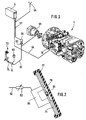
- a signal generator 8 is also arranged, which receives an electrical signal from the display switch 19 on the transmission 1 primarily via the electronic control unit 5 and line 55 and converts it into a haptic signal which is felt by the driver on the clutch pedal 7 when the circuit in Gear 1 is completed. The clutch can only be engaged again after this signal has been detected.
- This signal replaces the information about the completed shift in the case of an auxiliary switch, which can be felt in the case of a conventional manual shift device via the shift linkage on the shift lever or, for example, via optical or acoustic signals auxiliary switch devices informs the driver of a completed shift.
- the signal generator 8 is an electromagnet
- the haptic signal is transmitted to the clutch pedal 7 via the armature 81.
- the electromagnet 80 can also, as shown in Fig. 2, be arranged directly in the tread plate 75, so that the armature 81 directly or via a transmission plate 76 gives the haptic signal to a surface, for example a rubber plate or a profiled rubber 77, with which the step plate 65 is covered.
- the clutch pedal 70 is shown in connection with a master piston-cylinder unit 9, a pressure medium line 91 and a slave piston-cylinder unit 95.
- the piston of the slave cylinder unit is, as can be seen from FIG. 4, mechanically connected to the clutch release mechanism 180 of the clutch 190 and actuates it.
- Pressure medium losses are compensated for by a pressure medium container 92, and a pressure piston 93 acting on the pressure medium line 91 is actuated by an electromagnet 94 and acts as a signal generator for the haptic signal.
- the clutch is opened due to the actuated clutch pedal 70.
- FIG. 4 shows a possibility, in particular when the pressure medium for actuating the clutch and the gears is air, to the haptic signal acting on the clutch pedal 700 via a signal generator 10 in connection with an electro-pneumatic 3/2-way valve 120 produce.
- the 3/2-way valve such as the electromagnet 94, is activated in the transmission 1 after the circuit has been completed.
- Pressure medium is thus directed from a pressure medium source 110 to the signal generator 10 via the opened electrical 3/2-way valve 120.
- the actual haptic signal in the pressure line 130 is generated via a differential piston 101 and, as described in FIG. 3 and transmitted via the master piston-cylinder unit 140 and the linkage 150 to the clutch pedal 700.
- a pressure reducing valve 160 can also be arranged to define the haptic signal.
- the line 130 is, as described in FIG. 3, connected to the actuating piston-cylinder unit 170 for the clutch 190, the piston 171 being connected to the clutch release mechanism 180.
Landscapes
- Engineering & Computer Science (AREA)
- General Engineering & Computer Science (AREA)
- Mechanical Engineering (AREA)
- Physics & Mathematics (AREA)
- General Physics & Mathematics (AREA)
- Automation & Control Theory (AREA)
- Gear-Shifting Mechanisms (AREA)
- Hydraulic Clutches, Magnetic Clutches, Fluid Clutches, And Fluid Joints (AREA)
- Control Of Transmission Device (AREA)
- Arrangement And Mounting Of Devices That Control Transmission Of Motive Force (AREA)
Claims (8)
Applications Claiming Priority (2)
| Application Number | Priority Date | Filing Date | Title |
|---|---|---|---|
| DE3724272 | 1987-07-22 | ||
| DE3724272 | 1987-07-22 |
Publications (2)
| Publication Number | Publication Date |
|---|---|
| EP0368922A1 EP0368922A1 (fr) | 1990-05-23 |
| EP0368922B1 true EP0368922B1 (fr) | 1991-05-15 |
Family
ID=6332129
Family Applications (1)
| Application Number | Title | Priority Date | Filing Date |
|---|---|---|---|
| EP19880907056 Expired - Lifetime EP0368922B1 (fr) | 1987-07-22 | 1988-06-30 | Selecteur de vitesses a servocommande |
Country Status (6)
| Country | Link |
|---|---|
| US (1) | US5080207A (fr) |
| EP (1) | EP0368922B1 (fr) |
| JP (1) | JP2732876B2 (fr) |
| BR (1) | BR8807623A (fr) |
| DE (1) | DE3862865D1 (fr) |
| WO (1) | WO1989000515A1 (fr) |
Families Citing this family (24)
| Publication number | Priority date | Publication date | Assignee | Title |
|---|---|---|---|---|
| WO1990014534A1 (fr) * | 1989-05-16 | 1990-11-29 | Zahnradfabrik Friedrichshafen Ag | Systeme de changement de vitesse electro-pneumatique |
| IT1240160B (it) * | 1990-03-30 | 1993-11-27 | Giovanni Nicodano | Dispositivo di comando per un cambio di velocita' di autoveicoli |
| WO1992013552A1 (fr) * | 1991-02-05 | 1992-08-20 | Smithkline Beecham Corporation | Peptides inhibant l'aggregation et contenant un amide ou un ester aromatique |
| US5877897A (en) | 1993-02-26 | 1999-03-02 | Donnelly Corporation | Automatic rearview mirror, vehicle lighting control and vehicle interior monitoring system using a photosensor array |
| US6822563B2 (en) | 1997-09-22 | 2004-11-23 | Donnelly Corporation | Vehicle imaging system with accessory control |
| DE4419212A1 (de) * | 1994-06-01 | 1995-12-07 | Zahnradfabrik Friedrichshafen | Schaltvorrichtung für ein automatisches Getriebe |
| US6891563B2 (en) * | 1996-05-22 | 2005-05-10 | Donnelly Corporation | Vehicular vision system |
| US7655894B2 (en) | 1996-03-25 | 2010-02-02 | Donnelly Corporation | Vehicular image sensing system |
| DE59906471D1 (de) * | 1998-03-17 | 2003-09-11 | Wabco Gmbh & Co Ohg | Verfahren zur Steuerung eines Getriebes |
| DE10026498A1 (de) * | 2000-05-27 | 2001-11-29 | Zahnradfabrik Friedrichshafen | Verfahren und Vorrichtung zur Rückmeldung eines Signals an den Fahrer eines Kraftfahrzeugs |
| KR100429067B1 (ko) * | 2001-05-12 | 2004-04-28 | 삼영이엔씨 (주) | 선박엔진용 전자 레버 장치 |
| FR2828155B1 (fr) * | 2001-08-01 | 2003-11-28 | Peugeot Citroen Automobiles Sa | Dispositif d'alarme par vibration destine a informer un conducteur de vehicule automobile |
| DE10211946C1 (de) * | 2002-03-18 | 2003-07-31 | Siemens Ag | Steuer- oder Schaltelement für Fahrzeuge |
| AU2003225228A1 (en) | 2002-05-03 | 2003-11-17 | Donnelly Corporation | Object detection system for vehicle |
| US7526103B2 (en) | 2004-04-15 | 2009-04-28 | Donnelly Corporation | Imaging system for vehicle |
| US7603228B2 (en) * | 2006-05-25 | 2009-10-13 | Ford Global Technologies, Llc | Haptic apparatus and coaching method for improving vehicle fuel economy |
| WO2008024639A2 (fr) | 2006-08-11 | 2008-02-28 | Donnelly Corporation | Système de commande automatique de phare de véhicule |
| US8108136B2 (en) * | 2007-08-09 | 2012-01-31 | Ford Global Technologies, Llc. | Driver advisory system for fuel economy improvement of a hybrid electric vehicle |
| US9726088B2 (en) * | 2007-10-30 | 2017-08-08 | Ford Global Technologies, Llc | System and method for obtaining an adjustable accelerator pedal response in a vehicle powertrain |
| US8552847B1 (en) | 2012-05-01 | 2013-10-08 | Racing Incident Pty Ltd. | Tactile based performance enhancement system |
| US10359802B2 (en) | 2016-08-22 | 2019-07-23 | Cts Corporation | Variable force electronic vehicle clutch pedal |
| US10005359B2 (en) | 2016-09-06 | 2018-06-26 | Ford Global Technologies, Llc | Manual transmission driving assistant |
| CN106855120B (zh) * | 2016-12-29 | 2018-09-28 | 北奔重型汽车集团有限公司 | 一种车辆变速器换挡操纵的控制系统 |
| CN106763734B (zh) * | 2016-12-29 | 2018-09-18 | 北奔重型汽车集团有限公司 | 一种车辆变速器换挡操纵的控制方法 |
Family Cites Families (9)
| Publication number | Priority date | Publication date | Assignee | Title |
|---|---|---|---|---|
| GB598153A (en) * | 1944-09-01 | 1948-02-11 | Saurer Ag Adolph | An improved control arrangement for toothed-wheel change-speed gear |
| JPS5572421A (en) * | 1978-11-22 | 1980-05-31 | Nissan Motor Co Ltd | Vibration preventive device of clutch pedal |
| SE420295B (sv) * | 1980-11-28 | 1981-09-28 | Saab Scania Ab | Forfarande for automatiskt vexelval i en fordonstransmission |
| DE73280T1 (de) * | 1981-08-26 | 1983-08-04 | Deere & Co., 61265 Moline, Ill. | Anordnung fuer die gangschaltung fuer ein fahrzeug. |
| DE3314111A1 (de) * | 1983-04-19 | 1984-10-25 | Dr.Ing.H.C. F. Porsche Ag, 7000 Stuttgart | Einrichtung zur wegabhaengigen positionsangabe hydraulisch betaetigter schaltstangen |
| JPS59226738A (ja) * | 1983-06-03 | 1984-12-19 | Toyota Motor Corp | 副変速機のギア比切替駆動制御装置 |
| DE3333216A1 (de) * | 1983-09-14 | 1985-03-28 | Neuenstein Zahnradwerk | Schaltvorrichtung fuer ein handschaltgetriebe fuer kraftfahrzeuge |
| JPS6082220A (ja) * | 1983-10-11 | 1985-05-10 | Mitsui Eng & Shipbuild Co Ltd | ストレツチヤレベラのストレツチ量制御方法 |
| US4924992A (en) * | 1989-09-14 | 1990-05-15 | General Motors Corporation | Anti-vibration mechanism for a clutch pedal |
-
1988
- 1988-06-22 US US07/458,675 patent/US5080207A/en not_active Expired - Fee Related
- 1988-06-30 EP EP19880907056 patent/EP0368922B1/fr not_active Expired - Lifetime
- 1988-06-30 WO PCT/EP1988/000578 patent/WO1989000515A1/fr not_active Ceased
- 1988-06-30 JP JP63506180A patent/JP2732876B2/ja not_active Expired - Fee Related
- 1988-06-30 DE DE8888907056T patent/DE3862865D1/de not_active Expired - Lifetime
- 1988-06-30 BR BR888807623A patent/BR8807623A/pt not_active IP Right Cessation
Also Published As
| Publication number | Publication date |
|---|---|
| BR8807623A (pt) | 1990-05-29 |
| JP2732876B2 (ja) | 1998-03-30 |
| EP0368922A1 (fr) | 1990-05-23 |
| US5080207A (en) | 1992-01-14 |
| DE3862865D1 (de) | 1991-06-20 |
| JPH02504249A (ja) | 1990-12-06 |
| WO1989000515A1 (fr) | 1989-01-26 |
Similar Documents
| Publication | Publication Date | Title |
|---|---|---|
| EP0368922B1 (fr) | Selecteur de vitesses a servocommande | |
| DE10315253B4 (de) | Fahrzeug-Gaspedalvorrichtung | |
| DE10307508A1 (de) | Getriebebedienvorrichtung für ein Fahrzeug | |
| DE102008015874A1 (de) | Betätigungseinrichtung mit Haptikemulation | |
| EP3221615B1 (fr) | Procédé et dispositif pour faire fonctionner un véhicule automobile | |
| WO2000014437A1 (fr) | Dispositif de commande de boites de vitesses de vehicules | |
| DE19961087A1 (de) | Automatische Schaltsteuereinrichtung für ein elektronisch-pneumatisches Schaltsystem sowie Verfahren zu deren Steuerung | |
| WO2001074618A1 (fr) | Mode de manoeuvre pour vehicules a embrayage automatise | |
| DE3238219A1 (de) | Hilfskraftbetaetigtes getriebe | |
| DE10026498A1 (de) | Verfahren und Vorrichtung zur Rückmeldung eines Signals an den Fahrer eines Kraftfahrzeugs | |
| DE102018130587A1 (de) | Verfahren und steuerungssystem zum steuern eines elektronisch gesteuerten getriebes in einem fahrzeugantriebsystem | |
| DE3822316C2 (fr) | ||
| EP1668275B1 (fr) | Boîte de vitesses avec boîte de commutation electro-pneumatique | |
| DE102017004048A1 (de) | Steuerung eines Schaltgetriebes | |
| DE102005029567A1 (de) | Elektromechanische Parkbremse für automatisches oder automatisiertes Getriebe | |
| WO2005019704A1 (fr) | Boite de commutation electro-pneumatique | |
| DE3333216A1 (de) | Schaltvorrichtung fuer ein handschaltgetriebe fuer kraftfahrzeuge | |
| DE102008054846A1 (de) | Elektro-pneumatische Schalteinheit | |
| DE102005021414A1 (de) | Verfahren zum Aktivieren bzw. Deaktivieren eines Rangiermodus eines Kraftfahrzeuges | |
| DE102017209414A1 (de) | Getriebevorrichtung für einen Kraftwagen und Verfahren zum Betreiben einer Getriebevorrichtung | |
| DE10127762B4 (de) | Automatische Getriebeeinrichtung zum Verbessern des Schaltkomforts von mit diesem automatischen Getriebe ausgerüsteten Kraftfahrzeugen | |
| DE69314051T2 (de) | Abnutzungswarnvorrichtung einer hilfskraftbetätigten kupplung | |
| WO2004044462A1 (fr) | Unité électro-pneumatique de changement de vitesse | |
| DE19508976C1 (de) | Vorrichtung zur manuellen Betätigung eines schaltbaren Getriebes | |
| DE202007016437U1 (de) | Vorrichtung zur Beeinflussung eines Gaspedals eines Kraftfahrzeuges bei einem Bremsvorgang |
Legal Events
| Date | Code | Title | Description |
|---|---|---|---|
| PUAI | Public reference made under article 153(3) epc to a published international application that has entered the european phase |
Free format text: ORIGINAL CODE: 0009012 |
|
| 17P | Request for examination filed |
Effective date: 19891117 |
|
| AK | Designated contracting states |
Kind code of ref document: A1 Designated state(s): DE GB IT |
|
| 17Q | First examination report despatched |
Effective date: 19901005 |
|
| ITF | It: translation for a ep patent filed | ||
| GRAA | (expected) grant |
Free format text: ORIGINAL CODE: 0009210 |
|
| AK | Designated contracting states |
Kind code of ref document: B1 Designated state(s): DE GB IT |
|
| REF | Corresponds to: |
Ref document number: 3862865 Country of ref document: DE Date of ref document: 19910620 |
|
| GBT | Gb: translation of ep patent filed (gb section 77(6)(a)/1977) | ||
| RAP4 | Party data changed (patent owner data changed or rights of a patent transferred) |
Owner name: ZF FRIEDRICHSHAFEN AKTIENGESELLSCHAFT |
|
| PLBE | No opposition filed within time limit |
Free format text: ORIGINAL CODE: 0009261 |
|
| STAA | Information on the status of an ep patent application or granted ep patent |
Free format text: STATUS: NO OPPOSITION FILED WITHIN TIME LIMIT |
|
| 26N | No opposition filed | ||
| PGFP | Annual fee paid to national office [announced via postgrant information from national office to epo] |
Ref country code: GB Payment date: 19940523 Year of fee payment: 7 |
|
| PG25 | Lapsed in a contracting state [announced via postgrant information from national office to epo] |
Ref country code: GB Effective date: 19950630 |
|
| GBPC | Gb: european patent ceased through non-payment of renewal fee |
Effective date: 19950630 |
|
| PGFP | Annual fee paid to national office [announced via postgrant information from national office to epo] |
Ref country code: DE Payment date: 20040708 Year of fee payment: 17 |
|
| PG25 | Lapsed in a contracting state [announced via postgrant information from national office to epo] |
Ref country code: IT Free format text: LAPSE BECAUSE OF NON-PAYMENT OF DUE FEES;WARNING: LAPSES OF ITALIAN PATENTS WITH EFFECTIVE DATE BEFORE 2007 MAY HAVE OCCURRED AT ANY TIME BEFORE 2007. THE CORRECT EFFECTIVE DATE MAY BE DIFFERENT FROM THE ONE RECORDED. Effective date: 20050630 |
|
| PG25 | Lapsed in a contracting state [announced via postgrant information from national office to epo] |
Ref country code: DE Free format text: LAPSE BECAUSE OF NON-PAYMENT OF DUE FEES Effective date: 20060103 |