EP0368930B1 - Moteur ou alternateur - Google Patents
Moteur ou alternateur Download PDFInfo
- Publication number
- EP0368930B1 EP0368930B1 EP88907728A EP88907728A EP0368930B1 EP 0368930 B1 EP0368930 B1 EP 0368930B1 EP 88907728 A EP88907728 A EP 88907728A EP 88907728 A EP88907728 A EP 88907728A EP 0368930 B1 EP0368930 B1 EP 0368930B1
- Authority
- EP
- European Patent Office
- Prior art keywords
- rotor
- stator
- permanent magnet
- poles
- electric machine
- Prior art date
- Legal status (The legal status is an assumption and is not a legal conclusion. Google has not performed a legal analysis and makes no representation as to the accuracy of the status listed.)
- Expired - Lifetime
Links
- 230000004907 flux Effects 0.000 claims abstract description 30
- 239000000758 substrate Substances 0.000 claims abstract description 16
- 230000035699 permeability Effects 0.000 claims abstract description 12
- 238000004804 winding Methods 0.000 claims description 54
- 230000003287 optical effect Effects 0.000 claims description 13
- 239000000919 ceramic Substances 0.000 claims description 9
- 239000000463 material Substances 0.000 claims description 6
- 238000001514 detection method Methods 0.000 claims 1
- 238000013021 overheating Methods 0.000 claims 1
- 229910052761 rare earth metal Inorganic materials 0.000 abstract description 8
- 150000002910 rare earth metals Chemical class 0.000 abstract description 8
- XEEYBQQBJWHFJM-UHFFFAOYSA-N Iron Chemical group [Fe] XEEYBQQBJWHFJM-UHFFFAOYSA-N 0.000 description 27
- 238000010276 construction Methods 0.000 description 15
- 229910052742 iron Inorganic materials 0.000 description 13
- 238000003475 lamination Methods 0.000 description 12
- 229910000831 Steel Inorganic materials 0.000 description 11
- 239000010959 steel Substances 0.000 description 11
- 238000010586 diagram Methods 0.000 description 6
- 238000002347 injection Methods 0.000 description 5
- 239000007924 injection Substances 0.000 description 5
- 238000000034 method Methods 0.000 description 5
- 239000011347 resin Substances 0.000 description 4
- 229920005989 resin Polymers 0.000 description 4
- 230000008878 coupling Effects 0.000 description 3
- 238000010168 coupling process Methods 0.000 description 3
- 238000005859 coupling reaction Methods 0.000 description 3
- 230000006698 induction Effects 0.000 description 3
- 239000004033 plastic Substances 0.000 description 3
- 229920003023 plastic Polymers 0.000 description 3
- 229910000859 α-Fe Inorganic materials 0.000 description 3
- RYGMFSIKBFXOCR-UHFFFAOYSA-N Copper Chemical compound [Cu] RYGMFSIKBFXOCR-UHFFFAOYSA-N 0.000 description 2
- 241000286209 Phasianidae Species 0.000 description 2
- 230000009471 action Effects 0.000 description 2
- 239000003990 capacitor Substances 0.000 description 2
- 239000002131 composite material Substances 0.000 description 2
- 239000004020 conductor Substances 0.000 description 2
- 229910052802 copper Inorganic materials 0.000 description 2
- 239000010949 copper Substances 0.000 description 2
- 239000011152 fibreglass Substances 0.000 description 2
- 239000000126 substance Substances 0.000 description 2
- 239000002887 superconductor Substances 0.000 description 2
- 230000001360 synchronised effect Effects 0.000 description 2
- OKTJSMMVPCPJKN-UHFFFAOYSA-N Carbon Chemical compound [C] OKTJSMMVPCPJKN-UHFFFAOYSA-N 0.000 description 1
- 229910000976 Electrical steel Inorganic materials 0.000 description 1
- 230000005355 Hall effect Effects 0.000 description 1
- PXAWCNYZAWMWIC-UHFFFAOYSA-N [Fe].[Nd] Chemical compound [Fe].[Nd] PXAWCNYZAWMWIC-UHFFFAOYSA-N 0.000 description 1
- 230000033228 biological regulation Effects 0.000 description 1
- 230000015572 biosynthetic process Effects 0.000 description 1
- 229910052799 carbon Inorganic materials 0.000 description 1
- KPLQYGBQNPPQGA-UHFFFAOYSA-N cobalt samarium Chemical compound [Co].[Sm] KPLQYGBQNPPQGA-UHFFFAOYSA-N 0.000 description 1
- 230000005347 demagnetization Effects 0.000 description 1
- 230000001747 exhibiting effect Effects 0.000 description 1
- 238000010438 heat treatment Methods 0.000 description 1
- 150000002505 iron Chemical class 0.000 description 1
- 238000004519 manufacturing process Methods 0.000 description 1
- 229910052751 metal Inorganic materials 0.000 description 1
- 239000002184 metal Substances 0.000 description 1
- 239000000088 plastic resin Substances 0.000 description 1
- 230000009467 reduction Effects 0.000 description 1
- 229910000938 samarium–cobalt magnet Inorganic materials 0.000 description 1
- 239000004065 semiconductor Substances 0.000 description 1
- 239000007858 starting material Substances 0.000 description 1
- 229910052712 strontium Inorganic materials 0.000 description 1
- CIOAGBVUUVVLOB-UHFFFAOYSA-N strontium atom Chemical compound [Sr] CIOAGBVUUVVLOB-UHFFFAOYSA-N 0.000 description 1
- 239000002023 wood Substances 0.000 description 1
Images



Classifications
-
- H—ELECTRICITY
- H02—GENERATION; CONVERSION OR DISTRIBUTION OF ELECTRIC POWER
- H02K—DYNAMO-ELECTRIC MACHINES
- H02K23/00—DC commutator motors or generators having mechanical commutator; Universal AC/DC commutator motors
- H02K23/58—Motors or generators without iron cores
-
- H—ELECTRICITY
- H02—GENERATION; CONVERSION OR DISTRIBUTION OF ELECTRIC POWER
- H02K—DYNAMO-ELECTRIC MACHINES
- H02K1/00—Details of the magnetic circuit
- H02K1/02—Details of the magnetic circuit characterised by the magnetic material
-
- H—ELECTRICITY
- H02—GENERATION; CONVERSION OR DISTRIBUTION OF ELECTRIC POWER
- H02K—DYNAMO-ELECTRIC MACHINES
- H02K29/00—Motors or generators having non-mechanical commutating devices, e.g. discharge tubes or semiconductor devices
- H02K29/06—Motors or generators having non-mechanical commutating devices, e.g. discharge tubes or semiconductor devices with position sensing devices
- H02K29/10—Motors or generators having non-mechanical commutating devices, e.g. discharge tubes or semiconductor devices with position sensing devices using light effect devices
Definitions
- This invention relates to permanent magnet rotary dynamo electric machines of the type in which relative rotation occurs between a plurality of permanent magnetic poles and a plurality of wound poles.
- the wound poles being wound in the sense that they have associated therewith electric current carrying conductors.
- Perfect magnetic poles are generally provided by high strength permanent magnets formed of ceramic ferrites or rare earth magnets but they can also be provided by single or multi-turn closed loop(s) superconductors where the magnetic poles are permanent so long as the conductor is energised and remains in a superconducting state.
- the term "permanent magnet rotary dynamo electric machines” includes both motors and generators of direct or alternating current, and thus includes direct current generators as well as alternators.
- Electric motors and generators/alternators have traditionally been constructed in coaxial cylindrical formation with a central rotor having a plurality of wound poles formed by windings on steel laminations or on a soft iron core.
- the stator is a cylindrical casing surrounding the rotor, and requires accurate construction as there is only a narrow cylindrical gap between the rotor and stator of typically less than 0.25 mm for small machines, less than 5 kw.
- the stator also has a plurality of wound poles formed by windings in laminations inside a steel casing.
- Such silicon steel laminations generally have a high magnetic permeability of the order of 2000 (relative to air). Magnetic permeability of a material is conventionally expressed as a numerical value showing how many times it is greater than the magnetic permeability of air.
- the small high speed electric motors used in vacuum cleaners may run up to 30,000 rpm (ie 500 hertz) but are limited to operation of about one hour at a time because of eddy current heating problems associated with the iron laminations associated with the wound poles of both stator and rotor.
- the iron laminations In order to achieve these high speeds, within the frequency limitations imposed by the iron laminations they use only 2 brushes. If the number of brushes were increased there would be much greater losses, as well as greater complexity in the circuit used to control the motor.
- Another approach involves the use of permanent magnets and an ironless stator with a low effective coupling between them, to produce a motor exhibiting low torque. This approach is suitable for low power high speed DC motors.
- Teldix One example of such a motor is described in GB 1500955 by Teldix.
- the magnets are spaced apart from one another with resin in between them, so that by using a large number of small width bar magnets, the magnets in the external rotor correspond fairly closely to the radius of curvature of the inside of the rotor.
- Teldix suggests the use of 24 magnets grouped in such a way that there are only eight poles. These spaced apart magnetic poles create a low effective coupling between the flux lines and the windings as the Teldix windings intersect the flux lines at a shallow angle.
- the invention provides a brushless permanent magnet rotary dynamo electric machine including: at least one generally cylindrical stator and at least one generally cylindrical rotor rotatable about an axis and having a generally cylindrical surface facing said generally cylindrical stator and spaced apart therefrom by a generally cylindrical gap, a plurality of permanent magnetic poles in the form of bands parallel to the rotational axis on said surface of the rotor and positioned adjacent said generally cylindrical gap, said stator having a plurality of wound poles on or in a substrate of the stator characterised in that the majority of said wound poles are positioned on or in that surface of the stator which faces said rotor so that the wound poles are adjacent said cylindrical gap and at least said majority of the wound poles are positioned substantially parallel to the rotational axis of the rotor and the permanent magnetic poles are closely spaced around the generally cylindrical circumference of the rotor surface such that there are relatively short substantially semi-circular magnetic flux paths between circumferentially adjacent permanent magnetic poles, said relatively short magnetic flux paths
- the wound poles are of shallow depth and are wound on or close to the surface of the substrate.
- the substrate can be made of any material having a low magnetic permeability e.g. wood, fibreglass, plastics, plastics resins, or in some cases ferrites.
- the magnetic permeability of the substance is below 20 (relative to air).
- the wound poles could be wound on a removable mould and encapsulated within a plastics resin so that the resin forms the substrate.
- the wound poles are provided on or close to the outer cylindrical surface of a stator so that the permanent magnetic poles are provided on the inner surface of a surrounding cup shaped rotor.
- the rotor can be positioned within the stator, ie the positioning is reversed, in which case the permanent magnetic poles will be positioned on the outside of the rotor, and the wound poles will be on the inner cylindrical face of the stator.
- the permanent magnetic poles are to be positioned on the inner face of a rotating outer cylinder, it would be generally convenient to use a plurality of high strength bar magnets such as ceramic or rare earth magnets, mounted adjacent one another with their axes parallel to the axis of the rotor. By mounting them on the inside of the rotor, it is possible to withstand greater rotational speeds than would be possible with the magnets on the outside surface of the rotor.
- high strength bar magnets such as ceramic or rare earth magnets
- an electric motor or generator/alternator in accordance with this invention, with the magnets on the outer face of a rotor which is placed within a cylindrical stator.
- the cylindrical gap between the rotor and stator is greater than that used with conventional electric motors or conventional generators/alternators which require the presence of iron within the stator in order to provide a magnetic flux path in the stator.
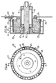
- the motor/alternator of this invention is preferably constructed using a series of adjacent bar magnets inside a steel annulus to form the rotor as shown in figure 1 a.
- the steel annulus provides two important functions:
- the motor alternator of this invention can also be constructed with the rotor as the inner element and the stator as the outside element, see figures 7a and 7b, but is not as advantageous as the external rotor construction because of the lower maximum rpm that the rotor of figure 7b can sustain due to the low tensile strength of ceramic and rare earth magnets when compared to the steel cup shaped rotor of figure 1 b.
- the internal rotor construction does have applications in the low to middle speed area as it lends itself to current construction techniques as used to manufacture small induction motors and alternators.
- the permanent magnets on the rotor so that electrical connections can be readily made to the wound poles on the stator.
- Such a construction can be referred to as an iron-less stator motor/alternator.
- Other configurations are possible. For example, if the co- axial iron-less direct current motor construction is controlled by carbon brushes and a commutator, it would then have the magnets stationary (stator) and the windings and commutator turning (rotor) and thus would have an ironless rotor rather than an ironless stator.
- Slotted optical switches have been used in the following examples to accurately sense position of the rotor and control transistors to switch direct current into the three phase stator windings, see figures 3, 4, 5, and 6.
- the rotor has a series of protrusions, one per magnetic pole pair and 120 degrees electrical to allow sequential current injection into the stator windings.
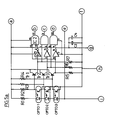
- Three optocouplers are used with logic gates to provide drive signals to the transistors, as shown in figure 5a, 5b, 5c. Also non-overlap logic is used, so that only one winding at a time has current flowing in it. Two or more phases could be used if desired, but generally three phases gives optimum efficiency with current conduction of 120 electrical degrees per phase.
- a co-axial motor or alternator having an external rotor construction utilizing bar magnets. Whether the unit is used as a motor or an alternator will depend upon the application required, and whether or not current is extracted from these from the stator windings, or whether current is supplied to the stator windings to operate the unit as a motor.
- the motor/alternator 10 has a cylindrical sleeve 11 which is conveniently in the form of a cup having an end face 12, which is attached to a central shaft 13.
- This shaft is preferably mounted within bearings 14, 15 mounted within a stator 16.
- the shaft has a tapped end 17 for connection to other machinery.
- the inner face 20 of the sleeve 11 is provided with a plurality of side by side bar magnets 27, aligned with their axes parallel to the axis of the rotor. It will be appreciated that there will be an even number of such closely spaced magnets, so that the polarity of the permanent magnetic poles alternates as one travels around the inner circumference presented by these magnets. [This differs from traditional motor designs where the magnetic poles are widely spaced and there are much longer flux paths through the iron of the stator/core].
- the magnets are preferably rare earth or ceramic bar magnets, and 20 such magnets are shown in Figure 1A, for the purpose of illustration. Any even number of such magnets can be used depending upon design criteria such as size, weight, price, availability and frequency. For medium speed machines 12 to 30 poles are preferred, with 20 permanent magnetic poles providing optimum performance for a motor of the type illustrated in figures 1 a and 1 b.
- the optimum ratio of magnetic circuit pole length (I) to magnet thickness (t) can be chosen, as shown in figure 8.
- the free air flux lines are shown as semi-circular whilst the metal rotor R provides a metallic return path for the flux
- the maximum length flux lines (f) approximate to semi-circular paths for higher pole numbers, and thus figure 8 approximates to a rotor of an infinitely large radius.
- the maximum length flux line (f) can be expressed as: Thus This relationship applies to strontium ferrite magnets, rare earth magnets such as samarium cobalt and neodymium iron, and also for air cored single or multiple loop superconductor electromagnets.
- the bar magnets are formed from either rare earth or ceramic magnets, and have a high field strength enabling them to provide a higher magnetic flux across a much wider air gap than is possible with conventional magnets, but at the same time it is preferred that the adjacent permanent magnetic poles are close together to provide a short magnetic flux path between adjacent magnetic poles.
- the rotor sleeve and end face are formed of steel although other materials could be used.
- the stator 16 is preferably connected to a mounting plate 22, which may also support slotted optical switches 23 (only one of which is shown) in order to detect the position of the magnets.
- the slotted optical switches 23 conveniently detect the position of protrusions 26 on the end face of the sleeve, which protrusions 26 may be associated with magnetic poles of a particular polarity.
- the rotor and stator are spaced apart by a relatively large cylindrical air gap 28 of the order of 0.25mm to 1.5mm and preferably 0.75mm for the 20 pole motor/alternator of this example. This enables the wound poles to intersect the magnetic flux path as shown in figure 3a.
- the air gap is preferably less than the depth of the magnets and should be of such a size as to allow for normal engineering clearances and tolerances.
- the stator has an annular generally cylindrical substrate 24 of low magnetic permeability material with a plurality of wound poles 25 on its outer cylindrical surface.
- a preferred substance is glass reinforced plastics as this can be formed into a sufficiently rigid cylindrical surface which on a prototype machine without a fan has not distorted in use.
- the number of wound poles correspond to the number of permanent magnetic poles inside the rotor.
- the wound poles are relatively shallow in that they are formed on or close to the surface of the substrate (unlike conventional wound poles which are wound within slots formed in steel laminations).
- the depth of the wound poles on or close to the surface of the stator will depend upon the size of the stator and required rating of the motor. In the example shown, the depth would be of the order of 1 mm to 10mm, and preferably about 3mm.
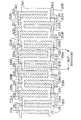
- FIG 4 shows the wave windings W1, W2, W3 each providing a plurality of wound poles 201 - 211, 201 A - 211 A, and 201 B - 211 B on the surface of a substrate for a three phase stator winding as used in the motor/alternator of figures 1 a/1 b.
- a three phase winding is preferred for most applications but other phases have their uses for particular applications. They may be exposed to the air on encapsulated in a plastic resin of low magnetic permeability.
- the wound poles may be provided in a variety of forms and may provide for one or more phases.
- the substrate is of low magnetic permeability there is consequently no iron (at least in the outer portion of the substrate) to provide a magnet flux path in the stator.
- the wound poles on the surface of the stator are so positioned as to intersect the magnetic flux lines connecting adjacent ceramic magnets as the flux lines essentially form a series of loops from one magnet to the next as one travels around the inner circumference of the rotor.
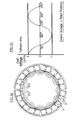
- figure 3a illustrates the relative position of two wound poles say 201 and 202 of wave winding on the surface of the stator and the relatively short magnetic flux paths between adjacent permanent magnetic poles on the rotor which intersect an outer annulus on the stator containing the wound poles.
- the average length of the magnetic flux path depicted as a series of semi-circles in Figure 3a is of the order of 16mm when the air gap between stator and rotor is 0.75mm and the depth of the wound poles is about 3mm.
- the average magnetic flux path length between adjacent permanent magnetic poles will be shorter than the average flux path length in a conventional synchronous motor where the path length is determined primarily by the size and geometry of the steel laminations surrounding the wound poles
- Figure 3b shows the stator voltage for different rotor positions for one phase only of the three phase stator windings of the motor/alternator of figures 1 a & 1 b.
- LED1- LED3 Light emitting diode, 3mm, green high efficiency
- FIG. 1 a/1 b The operation of a three phase motor as shown in figure 1 a/1 b will now be described with reference to Figures 5a, 5b, 5c and 6.
- the block diagram of Figure 6 shows the relationship of the following subsystems relative to the motor:
- the rotor position is sensed by the slotted optical switches OPT01-OPT03 and this information is converted by logic into three 120 degree non-overlapping signals to control the power transistors.
- the power transistors Tr17-21, Tr12-16 and Tr7-11 are connected to each of the three phase windings on the stator of the co-axial motor.
- IC6 is a pulse-width modulation device which can govern the rpm and maximum input current to the motor by varying the pulse width of a series choke DC-DC converter formed by inductor L and Transistors Tr22 - Tr26.
- Motor input current limitation is achieved by sensing the voltage drop across resistor R60, which IC6 senses via IC4/b and OPT04 and limits the pulse-width to provide current limiting.
- Motor rpm governing is achieved by rectification of the AC voltage generated in winding W3 and sensing of this voltage by IC6 via IC4/a and OPTO 4 to provide a pulse-width of suitable duty cycle.
- Rotor position is sensed by slotted optical switches, OPT01 - OPT03 which detect 120 electrical degree protrusions 26 on the rotor.
- IC1 and IC2 provide non-overlap logic so that only one winding at a time has current flowing in it. Also a time delay in switch-on resistors R11, R12 and R13 and capacitors C6; C7 and C8 provides additional 'dead-time' to allow current flowing in the previous motor winding to reduce to zero before the next winding has current flowing in it.
- IC3 provides the logic necessary for th electronic brake. While the motor is switched on the main power transistors Tr7 - Tr21 are turned on and off sequentially under the control of the optical slotted switches OPT01 - OPT03. The motor can be switched off by three different means:
- switch SW2 As an added safety device IC7 and switch SW2 provide a three second enabling period during which switch SW1 must be operated to allow the motor to start.
- the three phase motor of Figure 1 a/1 utilises slotted optical switches to provide rotor position information to control the point of switching of current into the motor windings. Due to the 120 electrical degree conduction angle technique used for this design, there exists other alternatives for accurately sensing rotor position. This is due to the 240 electrical degree period in which the voltage across the motor windings is purely the back EMF voltage generated by the action of the rotor turning.
- wound pole 201 B of winding W3 can indicate the point at which current should start to flow in wound pole 201 A of winding W2 and stop flowing in wound pole 201 of winding W1.
- winding W1 can indicate the point at which current should start to flow in winding W3 and stop flowing in winding W2. This can be used for accurate stepper motor control by switching the different windings to provide incremental movement.
- Another method of determining rotor position from the back EMF of the motor windings is by sensing the crossing points of the three voltage waveforms and using this information to determine when to switch "on” and "off” the appropriate winding.
- Magnetic sensors such as Hall Effect devices can be used in place of the optical slotted switches especially in dusty environments where problems with fully enclosing the motor exist.
- This arrangement is similar to that of example 1 except that a single cylindrical ring magnet 30 is provided on the inside of the cup shaped rotor 31. Similar protrusions 32 are provided around the edge of the rotor to identify the positions of the permanent magnetic poles of the ring magnet to a slotted optical switch as shown in figure 1 b.
- the stator (not shown) can be the same as that of figure 1 b.
- This arrangement has a single cylindrical ring magnet 41 on an internal rotor 40, i.e. the permanent magnetic poles are on the outer face of the rotor 40, and are surrounded by the wound poles 42 on the inner cylindrical face of the stator 43.
- the wound poles 42 are provided on a low-magnetic substrate 44 forming part of the stator.
- the rotor is mounted on shaft 45 which is mounted in bearings 46, 47 in end plates 48, 49.
- End plate 48 has an internal slotted optical switch 50 which detects the position of protrusions 51 on the edge of the rotor.
- phase windings may be used, and in particular 1,2 and 4 phase configurations will now be described.
- Single phase co-axial alternators are the most simple configuration of stator for this machine and can find uses where simplicity of construction outweighs absolute output power.
- the three phase equivalent produces twice the output power for the same resistive losses, and 50 per cent additional copper in the stator windings.
- Single phase co-axial motors are the most simple configuration of stator for this machine, but required some means of starting (similar to single phase induction motors) and therefore require an additional winding or mechanical means to ensure starting. In areas of low starting torque requirements i.e. direct coupled fans there could be a use for single phase motors.
- Two Phase Co-Axial Motors Due to two phase operation there are no starting problems, but if the machine is to be electronically controlled from a direct current supply then efficiency could be low if 180 degree current injection is used.
- the two phase motor could be electronically controlled to provide the 180 degree current injection just for starting and reduce to 120 degrees or less for normal running operation.
- This machine provides an increase in output power for the same resistive losses as a single or double phase machine. If the three phase machine uses the same amount of copper as a two phase machine and the stator windings of both machines occupy the full 360° available, then the three phase machine can produce a further 7% output power over the two phase machine for the same resistive losses (ie 47% increase over the single phase machine).
- Co-axial Motors Slightly higher efficiency possible due to possible smaller current injection angle.
- the four phase motor has possible applications, due to simplicity of electronically controlled reversing of rotor direction while still only requiring two slotted optical switches to sense rotor position.
- the wound poles are formed on one or the other of the rotor or the stator and the permanent magnetic poles are provided on the remaining one of the etator or the rotor.
- the rotor may be provided with a band of permanent magnetic poles then a band of wound poles (which may be repeated along its length) and the stator is provided with the opposite configuration so that a band of wound poles on the stator face the band of permanent magnetic poles on the rotor, and a band of permanent magnetic poles on the stator face the band of wound poles on the rotor.
- the closely spaced permanent magnetic poles can be provided by a single ring magnet (in which case the poles are contiguous) or by separate magnets which touch one another as in Figure 1 a, or are separated from one another by a small gap to allow for engineering tolerances (or thermal expansion).
- a gap would generally be less than 2% of the width 1 of the magnet as shown in Figure 8.
- the gap would be of the order of 3mm.
- the number of permanent magnetic poles will be chosen to suit the particular application of the motor and in particular the required maximum speed of the motor. Between 4 and 30 poles are preferred, the lower pole numbers being suited to small high speed machines, with the higher pole numbers being suited to medium speed and larger machines.
- the estimated maximum motor speed (s) in revolutions per minute (rpm) can be determined from the formula
Landscapes
- Engineering & Computer Science (AREA)
- Power Engineering (AREA)
- Permanent Magnet Type Synchronous Machine (AREA)
- Reciprocating, Oscillating Or Vibrating Motors (AREA)
Abstract
Claims (17)
Priority Applications (1)
| Application Number | Priority Date | Filing Date | Title |
|---|---|---|---|
| AT88907728T ATE104097T1 (de) | 1987-09-15 | 1988-09-12 | Motor oder generator. |
Applications Claiming Priority (5)
| Application Number | Priority Date | Filing Date | Title |
|---|---|---|---|
| NZ221822 | 1987-09-15 | ||
| NZ221822A NZ221822A (en) | 1987-09-15 | 1987-09-15 | Permanent magnet motor |
| US14438688A | 1988-01-26 | 1988-01-26 | |
| PCT/GB1988/000742 WO1989002671A1 (fr) | 1987-09-15 | 1988-09-12 | Moteur ou alternateur |
| US144386 | 1993-11-02 |
Publications (3)
| Publication Number | Publication Date |
|---|---|
| EP0368930A1 EP0368930A1 (fr) | 1990-05-23 |
| EP0368930B1 true EP0368930B1 (fr) | 1994-04-06 |
| EP0368930B2 EP0368930B2 (fr) | 1999-01-13 |
Family
ID=26650763
Family Applications (1)
| Application Number | Title | Priority Date | Filing Date |
|---|---|---|---|
| EP88907728A Expired - Lifetime EP0368930B2 (fr) | 1987-09-15 | 1988-09-12 | Moteur ou alternateur |
Country Status (6)
| Country | Link |
|---|---|
| EP (1) | EP0368930B2 (fr) |
| JP (1) | JPH03500358A (fr) |
| AU (1) | AU606748B2 (fr) |
| DE (1) | DE3888970T2 (fr) |
| HK (1) | HK80994A (fr) |
| WO (1) | WO1989002671A1 (fr) |
Cited By (8)
| Publication number | Priority date | Publication date | Assignee | Title |
|---|---|---|---|---|
| US7126313B2 (en) | 2003-05-27 | 2006-10-24 | Pratt & Whitney Canada Corp. | Architecture for electric machine |
| US7288923B1 (en) | 2006-04-21 | 2007-10-30 | Pratt & Whitney Canada Corp. | Voltage-limited electric machine |
| US7436098B2 (en) | 2003-03-21 | 2008-10-14 | Pratt & Whitney Canada Corp. | Current limiting means for a generator |
| US7443070B2 (en) | 2003-06-16 | 2008-10-28 | Pratt & Whitney Canada Corp. | Method and apparatus for controlling an electric machine |
| US7545056B2 (en) | 2003-05-27 | 2009-06-09 | Pratt & Whitney Canada Corp. | Saturation control of electric machine |
| US7583063B2 (en) | 2003-05-27 | 2009-09-01 | Pratt & Whitney Canada Corp. | Architecture for electric machine |
| CN101997527A (zh) * | 2010-09-28 | 2011-03-30 | 秦传勇 | 一种换向器控制电路及换向器 |
| US8458895B2 (en) | 2011-09-30 | 2013-06-11 | General Electric Company | Assembly for positioning a rotor retaining ring |
Families Citing this family (7)
| Publication number | Priority date | Publication date | Assignee | Title |
|---|---|---|---|---|
| DE3933790C2 (de) * | 1989-10-10 | 1994-03-17 | Werner Anwander | Elektrische Maschine mit einem Rotor und einem Stator |
| NZ232333A (en) * | 1990-02-01 | 1993-12-23 | Cadac Holdings Ltd | Motor stator wound with high permeability material. |
| JPH05215784A (ja) * | 1991-08-16 | 1993-08-24 | Sgs Thomson Microelectron Inc | 負荷電流サンプリング技術 |
| US5656880A (en) * | 1993-02-17 | 1997-08-12 | Cadac Limited | Discoidal dynamo-electric machine |
| US6920023B2 (en) | 2003-03-21 | 2005-07-19 | Pratt & Whitney Canada Corp. | Current limiting means for a generator |
| US7262539B2 (en) | 2004-11-26 | 2007-08-28 | Pratt & Whitney Canada Corp. | Saturation control of electric machine |
| DE102011111352B4 (de) * | 2011-08-29 | 2015-11-26 | Otto-Von-Guericke-Universität Magdeburg | Elektromotor mit eisenloser Wicklung |
Family Cites Families (16)
| Publication number | Priority date | Publication date | Assignee | Title |
|---|---|---|---|---|
| US2797376A (en) * | 1955-02-03 | 1957-06-25 | Robert C Meade | Electronic motor |
| US3280373A (en) * | 1962-09-06 | 1966-10-18 | Carrier Corp | Over-temperature protection system having means for simulating the temperature rise rate of a dynamoelectric machine and winding |
| US3667011A (en) * | 1970-07-15 | 1972-05-30 | Sperry Rand Corp | Brushless dc torque motor including commutator bars fed from a photo-commutation circuit |
| IT1034733B (it) | 1974-04-11 | 1979-10-10 | Teldix Gmbh | Macchina elettrica |
| FR2364562A1 (fr) * | 1976-09-13 | 1978-04-07 | Recupelec | Moteur a courant continu a fort couple et tres bon rendement |
| JPS5523716A (en) * | 1978-07-28 | 1980-02-20 | Epson Corp | Device for protecting and warning electronic equipment |
| US4354214A (en) * | 1979-09-11 | 1982-10-12 | Walton John F | Motor protection circuit |
| JPS58127579A (ja) * | 1982-01-20 | 1983-07-29 | Fanuc Ltd | 同期モ−タの停止方式 |
| CA1237184A (fr) * | 1982-06-07 | 1988-05-24 | David Turner | Machine electrique a aimant permanent de ferrite, et son emploi dans des dispositifs de traction pour vehicules |
| US4426606A (en) * | 1982-11-08 | 1984-01-17 | Sanyo Denki Co., Ltd. | Emergency stop device for brushless motors |
| US4618806A (en) * | 1985-02-11 | 1986-10-21 | Rotron, Inc. | Ironless, brushless DC motor with wave-winding |
| JPS61196720A (ja) * | 1985-02-22 | 1986-08-30 | 株式会社東芝 | モ−タ保護回路 |
| JPS62171412A (ja) * | 1985-10-21 | 1987-07-28 | 名商株式会社 | 車載用空調機の過熱防止付きモ−タ駆動装置 |
| JPS62118791A (ja) * | 1985-11-18 | 1987-05-30 | Sanyo Electric Co Ltd | 電動機の制御装置 |
| JPS62166792A (ja) * | 1986-01-20 | 1987-07-23 | Matsushita Electric Ind Co Ltd | モ−タ駆動装置 |
| US4733118A (en) * | 1986-09-22 | 1988-03-22 | Hhk Inc. | Low damping torque brushless D.C. motor |
-
1988
- 1988-09-12 DE DE3888970T patent/DE3888970T2/de not_active Expired - Lifetime
- 1988-09-12 JP JP63507244A patent/JPH03500358A/ja active Pending
- 1988-09-12 EP EP88907728A patent/EP0368930B2/fr not_active Expired - Lifetime
- 1988-09-12 WO PCT/GB1988/000742 patent/WO1989002671A1/fr not_active Ceased
- 1988-09-12 AU AU23297/88A patent/AU606748B2/en not_active Ceased
-
1994
- 1994-08-11 HK HK80994A patent/HK80994A/en not_active IP Right Cessation
Cited By (10)
| Publication number | Priority date | Publication date | Assignee | Title |
|---|---|---|---|---|
| US7436098B2 (en) | 2003-03-21 | 2008-10-14 | Pratt & Whitney Canada Corp. | Current limiting means for a generator |
| US7126313B2 (en) | 2003-05-27 | 2006-10-24 | Pratt & Whitney Canada Corp. | Architecture for electric machine |
| US7312550B2 (en) | 2003-05-27 | 2007-12-25 | Pratt & Whitney Canada Corp. | Architecture for electric machine |
| US7545056B2 (en) | 2003-05-27 | 2009-06-09 | Pratt & Whitney Canada Corp. | Saturation control of electric machine |
| US7583063B2 (en) | 2003-05-27 | 2009-09-01 | Pratt & Whitney Canada Corp. | Architecture for electric machine |
| US7443070B2 (en) | 2003-06-16 | 2008-10-28 | Pratt & Whitney Canada Corp. | Method and apparatus for controlling an electric machine |
| US7288923B1 (en) | 2006-04-21 | 2007-10-30 | Pratt & Whitney Canada Corp. | Voltage-limited electric machine |
| CN101997527A (zh) * | 2010-09-28 | 2011-03-30 | 秦传勇 | 一种换向器控制电路及换向器 |
| CN101997527B (zh) * | 2010-09-28 | 2012-07-04 | 秦传勇 | 一种换向器控制电路及换向器 |
| US8458895B2 (en) | 2011-09-30 | 2013-06-11 | General Electric Company | Assembly for positioning a rotor retaining ring |
Also Published As
| Publication number | Publication date |
|---|---|
| JPH03500358A (ja) | 1991-01-24 |
| EP0368930A1 (fr) | 1990-05-23 |
| DE3888970T2 (de) | 1994-09-15 |
| EP0368930B2 (fr) | 1999-01-13 |
| AU606748B2 (en) | 1991-02-14 |
| WO1989002671A1 (fr) | 1989-03-23 |
| DE3888970D1 (de) | 1994-05-11 |
| HK80994A (en) | 1994-08-19 |
| AU2329788A (en) | 1989-04-17 |
Similar Documents
| Publication | Publication Date | Title |
|---|---|---|
| US4924125A (en) | Electric motor or alternator | |
| EP0513094B1 (fr) | Stator pour machine dynamoelectrique | |
| EP0368930B1 (fr) | Moteur ou alternateur | |
| JP2832307B2 (ja) | 電動機 | |
| US6121705A (en) | Alternating pole AC motor/generator with two inner rotating rotors and an external static stator | |
| US4450396A (en) | Electrically controlled synchronous machine | |
| US4761590A (en) | Electric motor | |
| US6097124A (en) | Hybrid permanent magnet/homopolar generator and motor | |
| US20040108789A1 (en) | High torque brushless DC motors and generators | |
| WO1988002192A1 (fr) | Moteur a courant continu sans balais perfectionne | |
| JPS58500584A (ja) | 円盤型ブラシレスdcモ−タあるいは発電機 | |
| RU2180766C2 (ru) | Двухфазная, электронно-коммутируемая реактивная машина | |
| CN101499700A (zh) | 永磁推挽无刷电机 | |
| EP1012948B1 (fr) | Moteur électrique a haut rendement | |
| CN109546842B (zh) | 复合式励磁永磁调速器 | |
| RU2091966C1 (ru) | Машина постоянного тока и.г.скибицкого | |
| AU4987193A (en) | Dynamoelectric machine and stators therefor | |
| SU1403267A1 (ru) | Вентильный электродвигатель | |
| SU1169082A1 (ru) | Электродвигатель с муфтой | |
| RU2348098C1 (ru) | Электрическая машина | |
| TW201817129A (zh) | 無刷電機 | |
| SK284262B6 (sk) | Elektrické rotačné zariadenie | |
| TH19605A (th) | มอเตอร์ซินโครนัสเหนี่ยวนำแบบไม่มีแปรงถ่านที่มีสเตเตอร์สองชุด | |
| TH14433B (th) | มอเตอร์ซินโครนัสเหนี่ยวนำแบบไม่มีแปรงถ่านที่มีสเตเตอร์สองชุด |
Legal Events
| Date | Code | Title | Description |
|---|---|---|---|
| PUAI | Public reference made under article 153(3) epc to a published international application that has entered the european phase |
Free format text: ORIGINAL CODE: 0009012 |
|
| 17P | Request for examination filed |
Effective date: 19900312 |
|
| AK | Designated contracting states |
Kind code of ref document: A1 Designated state(s): AT BE CH DE FR GB IT LI LU NL SE |
|
| 17Q | First examination report despatched |
Effective date: 19920409 |
|
| RAP1 | Party data changed (applicant data changed or rights of an application transferred) |
Owner name: CADAC HOLDINGS LIMITED |
|
| GRAA | (expected) grant |
Free format text: ORIGINAL CODE: 0009210 |
|
| AK | Designated contracting states |
Kind code of ref document: B1 Designated state(s): AT BE CH DE FR GB IT LI LU NL SE |
|
| PG25 | Lapsed in a contracting state [announced via postgrant information from national office to epo] |
Ref country code: NL Free format text: LAPSE BECAUSE OF FAILURE TO SUBMIT A TRANSLATION OF THE DESCRIPTION OR TO PAY THE FEE WITHIN THE PRESCRIBED TIME-LIMIT Effective date: 19940406 Ref country code: LI Effective date: 19940406 Ref country code: CH Effective date: 19940406 Ref country code: BE Effective date: 19940406 Ref country code: AT Effective date: 19940406 |
|
| REF | Corresponds to: |
Ref document number: 104097 Country of ref document: AT Date of ref document: 19940415 Kind code of ref document: T |
|
| REF | Corresponds to: |
Ref document number: 3888970 Country of ref document: DE Date of ref document: 19940511 |
|
| ET | Fr: translation filed | ||
| ITF | It: translation for a ep patent filed | ||
| REG | Reference to a national code |
Ref country code: CH Ref legal event code: PL |
|
| K2C2 | Correction of patent specification (partial reprint) published |
Effective date: 19940406 |
|
| PG25 | Lapsed in a contracting state [announced via postgrant information from national office to epo] |
Ref country code: LU Free format text: LAPSE BECAUSE OF NON-PAYMENT OF DUE FEES Effective date: 19940930 |
|
| PLBI | Opposition filed |
Free format text: ORIGINAL CODE: 0009260 |
|
| EAL | Se: european patent in force in sweden |
Ref document number: 88907728.5 |
|
| 26 | Opposition filed |
Opponent name: SIEMENS AG Effective date: 19941221 |
|
| NLR1 | Nl: opposition has been filed with the epo |
Opponent name: SIEMENS AG |
|
| PLAW | Interlocutory decision in opposition |
Free format text: ORIGINAL CODE: EPIDOS IDOP |
|
| PLAW | Interlocutory decision in opposition |
Free format text: ORIGINAL CODE: EPIDOS IDOP |
|
| PGFP | Annual fee paid to national office [announced via postgrant information from national office to epo] |
Ref country code: FR Payment date: 19980727 Year of fee payment: 11 |
|
| PGFP | Annual fee paid to national office [announced via postgrant information from national office to epo] |
Ref country code: SE Payment date: 19980806 Year of fee payment: 11 |
|
| PGFP | Annual fee paid to national office [announced via postgrant information from national office to epo] |
Ref country code: GB Payment date: 19980907 Year of fee payment: 11 |
|
| PGFP | Annual fee paid to national office [announced via postgrant information from national office to epo] |
Ref country code: NL Payment date: 19980930 Year of fee payment: 11 |
|
| PUAH | Patent maintained in amended form |
Free format text: ORIGINAL CODE: 0009272 |
|
| STAA | Information on the status of an ep patent application or granted ep patent |
Free format text: STATUS: PATENT MAINTAINED AS AMENDED |
|
| PGFP | Annual fee paid to national office [announced via postgrant information from national office to epo] |
Ref country code: DE Payment date: 19981130 Year of fee payment: 11 |
|
| 27A | Patent maintained in amended form |
Effective date: 19990113 |
|
| AK | Designated contracting states |
Kind code of ref document: B2 Designated state(s): AT BE CH DE FR GB IT LI LU NL SE |
|
| REG | Reference to a national code |
Ref country code: CH Ref legal event code: AEN Free format text: AUFRECHTERHALTUNG DES PATENTES IN GEAENDERTER FORM |
|
| NLR2 | Nl: decision of opposition | ||
| PG25 | Lapsed in a contracting state [announced via postgrant information from national office to epo] |
Ref country code: DE Free format text: LAPSE BECAUSE OF FAILURE TO SUBMIT A TRANSLATION OF THE DESCRIPTION OR TO PAY THE FEE WITHIN THE PRESCRIBED TIME-LIMIT Effective date: 19990414 |
|
| ET3 | Fr: translation filed ** decision concerning opposition | ||
| NLV1 | Nl: lapsed or annulled due to failure to fulfill the requirements of art. 29p and 29m of the patents act | ||
| PG25 | Lapsed in a contracting state [announced via postgrant information from national office to epo] |
Ref country code: GB Free format text: LAPSE BECAUSE OF NON-PAYMENT OF DUE FEES Effective date: 19990912 |
|
| PG25 | Lapsed in a contracting state [announced via postgrant information from national office to epo] |
Ref country code: SE Free format text: THE PATENT HAS BEEN ANNULLED BY A DECISION OF A NATIONAL AUTHORITY Effective date: 19990929 |
|
| GBPC | Gb: european patent ceased through non-payment of renewal fee |
Effective date: 19990912 |
|
| EUG | Se: european patent has lapsed |
Ref document number: 88907728.5 |
|
| PG25 | Lapsed in a contracting state [announced via postgrant information from national office to epo] |
Ref country code: FR Free format text: LAPSE BECAUSE OF NON-PAYMENT OF DUE FEES Effective date: 20000531 |
|
| REG | Reference to a national code |
Ref country code: FR Ref legal event code: ST |
|
| PG25 | Lapsed in a contracting state [announced via postgrant information from national office to epo] |
Ref country code: IT Free format text: LAPSE BECAUSE OF NON-PAYMENT OF DUE FEES Effective date: 20050912 |