EP0369068B1 - Installation de stores vénitiens - Google Patents
Installation de stores vénitiens Download PDFInfo
- Publication number
- EP0369068B1 EP0369068B1 EP88310423A EP88310423A EP0369068B1 EP 0369068 B1 EP0369068 B1 EP 0369068B1 EP 88310423 A EP88310423 A EP 88310423A EP 88310423 A EP88310423 A EP 88310423A EP 0369068 B1 EP0369068 B1 EP 0369068B1
- Authority
- EP
- European Patent Office
- Prior art keywords
- drive
- slider
- guide
- bottom rail
- members
- Prior art date
- Legal status (The legal status is an assumption and is not a legal conclusion. Google has not performed a legal analysis and makes no representation as to the accuracy of the status listed.)
- Expired - Lifetime
Links
- 239000000463 material Substances 0.000 claims description 4
- 229920003023 plastic Polymers 0.000 claims description 4
- 239000004033 plastic Substances 0.000 claims description 4
- 230000000717 retained effect Effects 0.000 claims description 3
- 230000006835 compression Effects 0.000 claims description 2
- 238000007906 compression Methods 0.000 claims description 2
- 230000002411 adverse Effects 0.000 description 3
- 239000000956 alloy Substances 0.000 description 1
- 229910045601 alloy Inorganic materials 0.000 description 1
- 239000004411 aluminium Substances 0.000 description 1
- 229910052782 aluminium Inorganic materials 0.000 description 1
- XAGFODPZIPBFFR-UHFFFAOYSA-N aluminium Chemical compound [Al] XAGFODPZIPBFFR-UHFFFAOYSA-N 0.000 description 1
- 230000000712 assembly Effects 0.000 description 1
- 238000000429 assembly Methods 0.000 description 1
- 238000010276 construction Methods 0.000 description 1
- 230000008602 contraction Effects 0.000 description 1
- 238000001125 extrusion Methods 0.000 description 1
- 238000004553 extrusion of metal Methods 0.000 description 1
- 230000005484 gravity Effects 0.000 description 1
- 230000002787 reinforcement Effects 0.000 description 1
Images


Classifications
-
- E—FIXED CONSTRUCTIONS
- E06—DOORS, WINDOWS, SHUTTERS, OR ROLLER BLINDS IN GENERAL; LADDERS
- E06B—FIXED OR MOVABLE CLOSURES FOR OPENINGS IN BUILDINGS, VEHICLES, FENCES OR LIKE ENCLOSURES IN GENERAL, e.g. DOORS, WINDOWS, BLINDS, GATES
- E06B9/00—Screening or protective devices for wall or similar openings, with or without operating or securing mechanisms; Closures of similar construction
- E06B9/24—Screens or other constructions affording protection against light, especially against sunshine; Similar screens for privacy or appearance; Slat blinds
- E06B9/26—Lamellar or like blinds, e.g. venetian blinds
- E06B9/28—Lamellar or like blinds, e.g. venetian blinds with horizontal lamellae, e.g. non-liftable
- E06B9/30—Lamellar or like blinds, e.g. venetian blinds with horizontal lamellae, e.g. non-liftable liftable
- E06B9/32—Operating, guiding, or securing devices therefor
Definitions
- the present invention relates to venetian blind assemblies.
- Venetian blinds are traditionally mounted on the inner side of a window, although it is also quite common for them to be mounted on the outside. A problem arises with these blinds on the outside insofar as they are subject to weather conditions which can adversely affect their performance. In particular wind, rain and most importantly snow can affect the satisfactory operation of a venetian blind.
- One form of exterior venetian blind includes a conventional headrail and bottom rail and two side members which each include a guideway and a guide slot which extend generally longitudinally of each side member, each guide slot opening towards the other side member.
- a plurality of venetian blind slats extend generally horizontally between the side members and have pins extending laterally therefrom to be movable in the guide slots of the side member.
- a flexible drive element for example in the form of a chain, is associated with and movable in each of the side members for raising and lowering the blind.
- a drive shaft extends longitudinally through the headrail and is rotatable about its axis, means being provided to rotate the drive shaft in each of two opposite rotational senses.
- a tilter is usually associated with the drive shaft and is adapted to tilt the slats by means of collapsible slat supporting means, such as cords or tapes.
- a venetian blind assembly comprising a headrail, a bottom rail, two side members each including a guideway and a guide slot, extending longitudinally of each side member, each guide slot opening towards the other side member, a plurality of venetian blind slats extending generally horizontally between said side members, pins extending laterally from said slats and movable in the guide slots of the side members, a flexible drive element associated with and movable in each of the side members for positively raising and lowering the blind, a drive shaft extending longitudinally through the headrail and rotatable about its axis, means to rotate the drive shaft in each of two opposite rotational senses, a tilter driven by said drive shaft and adapted to tilt the slats, by means of collapsible slat supporting means, two drive members mounted one adjacent each end of the headrail and rotatable by the drive shaft, each flexible drive element extending up from its side member to a separate one of the
- each slider includes an open-topped recess which receives the relevant guide element
- the guide element will disengage from its open-topped recess in the associated slider so that the slider can continue to move downwardly. This prevents jamming of the drive system, which is allowed to continue and complete its operating cycle, while the bottom rail remains in its temporarily blocked position. Any damage to the flexible drive element or other associated parts is thereby prevented, while restoring the blind to subsequent operation is made easier.
- the drive members are driven by the drive shaft via a lost motion connection and this may comprise, adjacent each drive member, a first member driven directly by the drive shaft, a first abutment on each first member, an intermediate member positioned between each first member and its associated drive member, second and third abutments on said intermediate members and a fourth abutment on each drive member, the first and second abutments being engaged with one another after initial rotation of the first member, whereafter the intermediate member rotates with the first member and the third and fourth abutments are subsequently engageable with one another after further rotation of the first and intermediate members, whereafter the drive member rotates with these members.
- a coil spring is interposed between said first member and said drive member, said coil spring having a radially extending end engageable with said first member and expansable and contractable to act as a friction clutch between said first member and said drive member to induce additonal friction in a rotational sense corresponding to the lowering movement of said bottom rail, while reducing friction in the reverse rotational sense.
- each side member is preferably of a continuous shaped profile which includes first and second tracks wherein said flexible drive element is capable of being moved under tension and compression and guided in the guide tracks of the associated side member, and wherein each flexible drive element extends up from the first guide track of its side member over a separate one of the drive members to be driven thereby and then down through the second guide track of that side member.
- the flexible drive element may take many forms, in a preferred construction, it comprises a tape made of a plastics material such as that sold by E.I. Du Pont de Nemour under the Trade Mark DYMETROL, this tape being provided with equally spaced apertures therein, and each drive member includes teeth drivingly engageable in these apertures.
- Each slider advantageously itself has projections engageable in the apertures to hold the slider in place with respect to the flexible drive element.
- the assembly includes, positioned at the top of each profiled side member, a support base having bearing surfaces for mounting the associated drive members, and guide surfaces shaped to guide smoothly the flexible drive element as it passes over the drive member.
- the assembly further comprises latches mounted adjacent, but spaced from, the lower ends of the side members, said latches being positioned to engage the guide element therein when the bottom rail is in its lowermost position and which are effective, when the bottom rail is externally lifted out of the recess in the associated slider which is then being retained by its drive element, thereby to prevent the rail being lifted further, said slider when driven to raise or lower the bottom rail, normally retracting the latch to enable the bottom rail to be lifted and lowered by movement of the slider under the action of the drive element without obstruction from the latches.
- the blind will be retained against wind loads during adverse weather conditions and it will be difficult for a prospective burglar to break into the building because the latches will prevent the bottom rail from being raised and will allow the venetian blind to act as a locked shutter.
- the latches each comprise a leaf spring extending vertically within the side member, the leaf spring being secured at one end to the side member and having a raised central portion at the junction of upper and lower ramps, and an aperture formed in the lower ramp, said aperture being engageable by the guide element on the end of the bottom rail adjacent thereto, when the bottom rail is manually raised, the two ramps normally being flattened towards the side member by the slider to enable the guide element to move past.
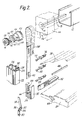
- an external venetian blind assembly including a conventional headrail 10 incorporating a tilter 12 driven in rotation by a drive shaft 13 ( Figure 2) to operate tilt cords 14.
- a plurality of slats 16 are caused to tilt by the cords 14 and mounted below these is a bottom rail 18.
- a housing at each longitudinal end of the headrail 10 carrying a lifting mechanism is indicated by the general reference numeral 20.
- On the lefthand side as indicated and also on the righthand side (not shown) is a side member 22, the other side member being a mirror image of the side member shown in the drawing.
- Each side member is formed as an extrusion of metal, such as aluminium or an alloy, the extrusion having a constant cross-section.
- This cross-section includes a guideway 24, first and second guide tracks 26 and 28 and a guide slot 30, the latter opening in a direction to face the other side member.
- a slider 32 Longitudinally slidable within the guideway 24 is a slider 32 which can be formed of a plastics material and including an open-topped recess 34 and a number of projections 36.
- Guided within the first and second tracks 26, 28 is a flexible drive member 38 formed of a plastics material sold by E.I. Du Pont de Nemour under the Trade Mark DYMETROL, this being provided with a series of equally spaced apart apertures 40, the spacing of which is such as to enable the projections 36 to engage in the lowest three apertures 40. The spacing is also chosen so that the apertures can engage circumferentially spaced teeth 44 on a drive member 46 over which the flexible drive element 38 passes.
- Drive member 46 is mounted within the lift mechanism housing 20 in a bearing 48 of a support base 50 engaged in the upper end of the side member, this being provided with guide surfaces 52 shaped to guide the tape smoothly into the tracks 26, 28.
- an intermediate member 54 which is mounted for limited rotation within the drive member 46.
- a first member 56 having a square cross-section opening 58 for engagement over the drive shaft 13.
- the first member 56 includes a first abutment 60 engageable with a second abutment 62 on the intermediate member.
- a third abutment 64 on the intermediate member is engageable with a fourth abutment 66 on the drive member 46.
- a coiled clutch spring 68 Surrounding the first member 56 is a coiled clutch spring 68 having a radially extending end 70 engageable in one of several slots 72 formed on the drive member 46.
- Each slat 16 is provided at each end with a pin 74 having a clip 76 at one end to engage in an opening 78 of the slat, and at the other end with a rearwardly or forwardly extending arm 80.
- the pin 74 is dimensioned to engage in the guide slot 30, the arms 80 being used to restrain the pin in this slot.
- the bottom rail 18 is provided with a guide element 82 engaged in an opening 89 in the end of the bottom rail.
- the guide element 82 which may be provided with an additional reinforcement strip 86 which is formed with an end portion 88 shaped to pass through the guide slot 30 and engage in the open-topped recess 34 of the slider 32.
- a latch 90 Adjacent the bottom of each side member 22, within the guideway 24, is a latch 90 in the form of a leaf spring secured at its lower end by a screw or the like (not shown), the leaf spring including a raised central portion 92 formed by a lower ramp 94, having an aperture 96 therein, and an upper ramp 98.
- the latch 90 is so positioned that, in normal operation, it is flattened by the slider 32 riding over the raised portion of the latch. In the lowermost position of the blind, the slider is below the latch with the upper end of the aperture 96 located immediately above the end portion 88 of the guide element 82.
- the latch is designed as a general retaining device and also as an anti-theft device so that if somebody raises the external blind by grabbing the bottom rail 18 and raising it, because the slider 32 is positively held at the lower position, with the raised central portion 92 slightly above the recess 34 of the slider, the end portion 88 of the guide element 82 will engage in the aperture 96 and thereby be prevented from raised any further. However, if one then operates internally the drive member 46, the drive element 38 will pull the slider 32 upwardly and the edge 35 of the recess 34 will engage the lower ramp 94 and thereby flatten the latch leaf spring to disengage the aperture 96 from the end 88 of the guide element 82.
- Drive to the tilter from the drive shaft 13 is provided by a conventional clutch arrangement which allows the drive shaft to continue to rotate after the slats have been fully tilted in either direction.
Landscapes
- Engineering & Computer Science (AREA)
- Structural Engineering (AREA)
- Architecture (AREA)
- Civil Engineering (AREA)
- Blinds (AREA)
- Transition And Organic Metals Composition Catalysts For Addition Polymerization (AREA)
- Electroluminescent Light Sources (AREA)
- Paper (AREA)
Claims (11)
- Store vénitien assemblé comprenant un rail de tête (1),un rail inférieur (18), deux éléments latéraux (22) comprenant chacun une surface de guidage (24) et une fente de guidage (30), s'étendant dans le sens longitudinal de chaque élément latéral, chaque fente de guidage (30) débouchant vers l'autre élément latéral; une multitude de lames (16) pour store vénitien s'étendant généralement dans le sens horizontal entre lesdits éléments latéraux (22), des axes (74) s'étendant latéralement à partir desdites lames et mobiles dans les fentes de guidage (30) des éléments latéraux (22), un élément d'entraînement flexible (38) associé à chacun des éléments latéraux (22) et mobile avec lui, pour élever et abaisser sûrement le store, un arbre d'entraînement (13) s'étendant longitudinalement à travers le rail de tête (10) et pouvant tourner autour de son axe, un moyen pour faire tourner l'arbre d'entraînement (13) dans chacun des deux sens de rotation opposés, un élément de basculement (12) entraîné par ledit arbre d'entraînement (13) et destiné à basculer les lames (16), par des moyens de support de lame pliables (14), deux éléments d'entraînement (46) montés en étant chacun contigus à chaque extrémité du rail de tête et pouvant être mis en rotation par l'arbre d'entraînement (13), chaque élément d'entraînement flexible (38) s'étendant vers le haut à partir de son élément latéral jusqu,à un élément séparé des éléments d'entraînement de manière à être entraîné vers le haut et vers le bas, une coulisse (32) mobile dans la surface de guidage (24) de chaque élément latéral et fixée à l'élément d'entraînement associé (38) et un élément de guidage s'étendant latéralement (82) sur chaque extrémité du rail inférieur, placé de façon à s'étendre à travers la fente de guidage (30) et à venir en contact avec la coulisse (32) de l'élément latéral associé, caractérisé en ce qu'un évidement à partie supérieure ouverte (34) ménagé dans chaque coulisse (32) reçoit l'élément de guidage approprié, chaque élément de guidage (82) pouvant se désengager de l'évidement à partir supérieure ouverte (34) de la coulisse associée lorsque le rail inférieur (18) et/ou la coulisse (32) sont entraînés dans la direction appropriée.
- Ensemble selon la revendication 1, dans lequel lesdits éléments d'entraînement (46) sont entraînés par l'arbre d'entraînement (13) via une liaison à mouvement perdu.
- Ensemble selon la revendication 2, dans lequel ladite liaison à mouvement perdu comprend, à un endroit contigu à chaque élément d'entraînement (46), un premier élément (56) entraîné directement par l'arbre d'entraînement (13), une première butée (60) sur chaque premier élément (56), un élément intermédiaire (54) placé entre chaque premier élément (56) et son élément d'entraînement associé (46), des seconde (62) et troisième (64) butées sur ledit élément intermédiaire (54) et une quatrième butée (66) sur chaque élément d'entraînement (46), les première et seconde butées étant en contact l'une avec l'autre après la rotation initiale du premier élément (56), à la suite de quoi l'élément intermédiaire (54) tourne avec le premier élément et les troisième et quatrième butées viennent en suite en contact l'une avec l'autre après une nouvelle rotation du premier élément et de l'élément intermédiaire, à la suite de quoi l'élément d'entraînement (46) tourne avec ces éléments.
- Ensemble selon la revendication 3, dans lequel un ressort en spirale (68) est interposé entre ledit premier élément (56) et ledit élément d'entraînement (46), ledit ressort en spirale ayant une extrémité s'étendant radialement (70) pouvant être en contact avec ledit premier élément (56) et pouvant se détendre et se contracter pour agir en embrayage à friction entre ledit premier élément (56) et ledit élément d'entraînement (46) pour provoquer un frottement supplémentaire dans un sens de rotation correspondant au mouvement d'abaissement dudit rail inférieur, tout en réduisant le frottement dans le sens de rotation opposé.
- Ensemble selon l'une quelconque des revendications précédentes, dans lequel chaque élément latéral (22) est un profilé de forme continue qui comporte des première et seconde pistes de guidage (26, 28) où ledit élément d'entraînement flexible (38) peut se déplacer sous traction et compression et être guidé dans les pistes de guidage (26, 29) de l'élément latéral associé, et où chaque élément d'entraînement flexible (38) s'étend vers le haut à partir de la première piste de guidage (26) de son élément latéral sur un élément séparé des éléments d'entraînement (46) pour être ainsi entraîné alors vers le bas dans la seconde piste de guidage (20) de cet élément latéral.
- Ensemble selon l'une quelconque des revendications précédentes, dans lequel l'élément d'entraînement flexible (38) est une bande d'entraînement en matière plastique présentant des ouvertures espacées de la même distance les unes des autres (40), et dans lequel chaque élément d'entraînement (46) comporte des dents (44) pouvant s'engager de manière motrice dans lesdites ouvertures (40).
- Ensemble selon la revendication 6, dans lequel chaque coulisse (32) comporte des saillies (36) pouvant s'engager dans lesdites ouvertures (40) pour maintenir ladite coulisse (32) en place par rapport audit élément d'entraînement flexible (38).
- Ensemble selon l'une quelconque des revendications précédentes et comportant en outre, positionnées au sommet de chaque élément latéral profilé (22), une base de support (50) présentant des surfaces d'appui (48) pour monter les éléments d'entraînement associés (46), et des surfaces de guidage (52) façonnées de manière à guider sans à-coup l'élément d'entraînement flexible (38) alors qu'il passe sur l'élément d'entraînement (46).
- Ensemble selon l'une quelconque des revendications précédentes, et comprenant en outre des cliquets (90) montés en étant contigus, mais en en étant espacés, aux extrémités inférieures des éléments latéraux (22), lesdits cliquets (90) étant placés de manière à venir en contact avec l'élément de guidage (82) lorsque le rail inférieur (18) se trouve dans sa position la plus basse et qui sont opérationnels, lorsque le rail inférieur est soulevé extérieurement de l'évidement (34) de la coulisse associé (32) qui est alors retenue par son élément d'entraînement (38), ce qui empêche que le rail (18) ne soit soulevé davantage, ladite coulisse (32) lorsqu'elle est entraînée pour élever ou abaisser le rail inférieur (19), rétractant normalement le cliquet (90) pour permettre au rail inférieur (18) d'être élevé et abaissé par le mouvement de la coulisse (32) sous l'action de l'élément d'entraînement (38) sans obstruction de la part des cliquets (90).
- Ensemble selon la revendication 9, dans lequel les cliquets (90) comprennent chacun un ressort à lame s'étendant verticalement à l'intérieur de l'élément latéral, le ressort à lame étant fixé à une extrémité à l'élément latéral (22) et présentant une partie centrale en élévation (92) à la jonction de rampes supérieure (98) et inférieure (94), et une ouverture (96) ménagée dans la rampe inférieure (94), ladite ouverture (96) pouvant recevoir l'élément de guidage (82) placé sur l'extrémité du rail inférieur (18) qui lui est adjacente, lorsque le rail inférieur (18) est élevé extérieurement, les deux rampes (94, 98) étant normalement aplaties vers l'élément latéral par la coulisse (32) de façon à permettre à l'élément de guidage (92) de passer à son niveau.
- Ensemble selon l'une quelconque des revendications précédentes, dans lequel lesdits axes (74) associés à chaque lame (16) comportent des bras s'étendant vers l'avant et vers l'arrière (80) pour maintenir les axes dans les fentes de guidage (30).
Priority Applications (5)
| Application Number | Priority Date | Filing Date | Title |
|---|---|---|---|
| EP88310423A EP0369068B1 (fr) | 1988-11-04 | 1988-11-04 | Installation de stores vénitiens |
| DE8888310423T DE3877360T2 (de) | 1988-11-04 | 1988-11-04 | Lamellenjalousievorrichtung. |
| AT88310423T ATE84347T1 (de) | 1988-11-04 | 1988-11-04 | Lamellenjalousievorrichtung. |
| ES198888310423T ES2037239T3 (es) | 1988-11-04 | 1988-11-04 | Conjunto de persiana veneciana. |
| AU40878/89A AU616047B2 (en) | 1988-11-04 | 1989-08-29 | Venetian blind assembly |
Applications Claiming Priority (1)
| Application Number | Priority Date | Filing Date | Title |
|---|---|---|---|
| EP88310423A EP0369068B1 (fr) | 1988-11-04 | 1988-11-04 | Installation de stores vénitiens |
Publications (2)
| Publication Number | Publication Date |
|---|---|
| EP0369068A1 EP0369068A1 (fr) | 1990-05-23 |
| EP0369068B1 true EP0369068B1 (fr) | 1993-01-07 |
Family
ID=8200275
Family Applications (1)
| Application Number | Title | Priority Date | Filing Date |
|---|---|---|---|
| EP88310423A Expired - Lifetime EP0369068B1 (fr) | 1988-11-04 | 1988-11-04 | Installation de stores vénitiens |
Country Status (5)
| Country | Link |
|---|---|
| EP (1) | EP0369068B1 (fr) |
| AT (1) | ATE84347T1 (fr) |
| AU (1) | AU616047B2 (fr) |
| DE (1) | DE3877360T2 (fr) |
| ES (1) | ES2037239T3 (fr) |
Families Citing this family (8)
| Publication number | Priority date | Publication date | Assignee | Title |
|---|---|---|---|---|
| DE4310868A1 (de) * | 1993-04-02 | 1994-10-06 | Teba Gmbh & Co | Antriebsvorrichtung für eine Lamellenjalousie, insbesondere für Dachfenster |
| DE29615252U1 (de) * | 1996-09-02 | 1998-01-08 | Hüppe Form Sonnenschutz- und Raumtrennsysteme GmbH., 26133 Oldenburg | Rafflamellenjalousie |
| CH691916A5 (de) * | 1997-01-15 | 2001-11-30 | Nyffenegger Storenfabrik Ag | Einrichtung mit einem verstellbaren Organ zum Schutz gegen Licht und/oder Witterung und/oder Einbruch und/oder zum Umlenken von Licht. |
| DE29913131U1 (de) * | 1999-07-27 | 2000-12-07 | Hüppe Form Sonnenschutzsysteme GmbH, 26133 Oldenburg | Lamellenjalousie |
| EP1264958B1 (fr) * | 2001-06-05 | 2004-09-01 | Hugo Tobler | Dispositif d'ombrage avec un rideau mobile |
| PT2245254E (pt) * | 2008-02-15 | 2011-11-04 | Hunter Douglas Ind Bv | Mecanismo de rotação de persianas |
| US9057219B1 (en) | 2011-08-30 | 2015-06-16 | Newell Window Furnishings, Inc. | Window covering with integrated side track |
| AU2017204189B1 (en) * | 2017-06-21 | 2018-04-12 | Taicang Kingfu Plastic Manufacture Co., Ltd. | Venetian blind |
Family Cites Families (4)
| Publication number | Priority date | Publication date | Assignee | Title |
|---|---|---|---|---|
| US2639766A (en) * | 1947-05-13 | 1953-05-26 | Raymond C Pratt | Closure structure |
| DE2657004A1 (de) * | 1975-12-23 | 1977-07-07 | Gross Hans | Antriebsvorrichtung fuer lamellenvorhaenge |
| US4199019A (en) * | 1977-09-01 | 1980-04-22 | Griesser Ag | Venetian blind construction |
| DE3037701A1 (de) * | 1980-10-06 | 1982-07-15 | Emil Schenker AG, 5012 Schönenwerd | Rafflamellenstore, rolladen o.dgl. |
-
1988
- 1988-11-04 ES ES198888310423T patent/ES2037239T3/es not_active Expired - Lifetime
- 1988-11-04 AT AT88310423T patent/ATE84347T1/de not_active IP Right Cessation
- 1988-11-04 EP EP88310423A patent/EP0369068B1/fr not_active Expired - Lifetime
- 1988-11-04 DE DE8888310423T patent/DE3877360T2/de not_active Expired - Fee Related
-
1989
- 1989-08-29 AU AU40878/89A patent/AU616047B2/en not_active Ceased
Also Published As
| Publication number | Publication date |
|---|---|
| AU616047B2 (en) | 1991-10-17 |
| EP0369068A1 (fr) | 1990-05-23 |
| AU4087889A (en) | 1990-05-10 |
| DE3877360D1 (de) | 1993-02-18 |
| DE3877360T2 (de) | 1993-05-06 |
| ES2037239T3 (es) | 1993-06-16 |
| ATE84347T1 (de) | 1993-01-15 |
Similar Documents
| Publication | Publication Date | Title |
|---|---|---|
| US7021360B2 (en) | One-way drive for window coverings | |
| CA2240206C (fr) | Mecanisme d'orientation pour un store venitien | |
| US5566738A (en) | Louvered movable window shutter | |
| EP0296420B1 (fr) | Volet pour fenêtre | |
| US5117893A (en) | Rolling shutter system | |
| US5228238A (en) | Transparent storm shutter | |
| US5573050A (en) | Locking device for a slatted roll-up gate or door | |
| US5645685A (en) | Venetian blinds | |
| EP1056921B1 (fr) | Volet roulant | |
| SE451614B (sv) | Jalusianordning | |
| EP0369068A1 (fr) | Installation de stores vénitiens | |
| US4444241A (en) | Blind or shutter for windows or the like | |
| US6619366B2 (en) | Universal head rail | |
| US7174941B2 (en) | One-way drive for window coverings | |
| WO1998042942A1 (fr) | Ensemble barres de securite | |
| US5983971A (en) | Reinforced burglar- and storm-resistant cover for windows and doors | |
| US20060169418A1 (en) | Window covering leveling method | |
| CA1142844A (fr) | Store venitien | |
| US20060130980A1 (en) | Window covering leveling mechanism | |
| US4505070A (en) | Window blind | |
| JP7463152B2 (ja) | 建築用電動シャッター装置 | |
| PL181410B1 (pl) | Urzadzenie do zabezpieczania nawijanego na walek elementu zamykajacego PL | |
| NL8401204A (nl) | Blokkeringssysteem. | |
| EP4191014B1 (fr) | Store de fenêtre à monter à l'extérieur d'une fenêtre | |
| JPH11152975A5 (fr) |
Legal Events
| Date | Code | Title | Description |
|---|---|---|---|
| PUAI | Public reference made under article 153(3) epc to a published international application that has entered the european phase |
Free format text: ORIGINAL CODE: 0009012 |
|
| AK | Designated contracting states |
Kind code of ref document: A1 Designated state(s): AT BE CH DE ES FR GB GR IT LI LU NL SE |
|
| RBV | Designated contracting states (corrected) |
Designated state(s): AT CH DE ES FR IT LI NL SE |
|
| 17P | Request for examination filed |
Effective date: 19900704 |
|
| 17Q | First examination report despatched |
Effective date: 19910827 |
|
| GRAA | (expected) grant |
Free format text: ORIGINAL CODE: 0009210 |
|
| AK | Designated contracting states |
Kind code of ref document: B1 Designated state(s): AT CH DE ES FR IT LI NL SE |
|
| REF | Corresponds to: |
Ref document number: 84347 Country of ref document: AT Date of ref document: 19930115 Kind code of ref document: T |
|
| REF | Corresponds to: |
Ref document number: 3877360 Country of ref document: DE Date of ref document: 19930218 |
|
| ITF | It: translation for a ep patent filed | ||
| ET | Fr: translation filed | ||
| REG | Reference to a national code |
Ref country code: ES Ref legal event code: FG2A Ref document number: 2037239 Country of ref document: ES Kind code of ref document: T3 |
|
| PLBE | No opposition filed within time limit |
Free format text: ORIGINAL CODE: 0009261 |
|
| STAA | Information on the status of an ep patent application or granted ep patent |
Free format text: STATUS: NO OPPOSITION FILED WITHIN TIME LIMIT |
|
| 26N | No opposition filed | ||
| PGFP | Annual fee paid to national office [announced via postgrant information from national office to epo] |
Ref country code: SE Payment date: 19941027 Year of fee payment: 7 |
|
| EAL | Se: european patent in force in sweden |
Ref document number: 88310423.4 |
|
| PGFP | Annual fee paid to national office [announced via postgrant information from national office to epo] |
Ref country code: NL Payment date: 19951012 Year of fee payment: 8 |
|
| PG25 | Lapsed in a contracting state [announced via postgrant information from national office to epo] |
Ref country code: SE Effective date: 19951105 |
|
| PGFP | Annual fee paid to national office [announced via postgrant information from national office to epo] |
Ref country code: FR Payment date: 19951109 Year of fee payment: 8 |
|
| PGFP | Annual fee paid to national office [announced via postgrant information from national office to epo] |
Ref country code: ES Payment date: 19951117 Year of fee payment: 8 |
|
| EUG | Se: european patent has lapsed |
Ref document number: 88310423.4 |
|
| PG25 | Lapsed in a contracting state [announced via postgrant information from national office to epo] |
Ref country code: ES Free format text: LAPSE BECAUSE OF EXPIRATION OF PROTECTION Effective date: 19961105 |
|
| PG25 | Lapsed in a contracting state [announced via postgrant information from national office to epo] |
Ref country code: NL Effective date: 19970601 |
|
| PG25 | Lapsed in a contracting state [announced via postgrant information from national office to epo] |
Ref country code: FR Effective date: 19970731 |
|
| NLV4 | Nl: lapsed or anulled due to non-payment of the annual fee |
Effective date: 19970601 |
|
| REG | Reference to a national code |
Ref country code: FR Ref legal event code: ST |
|
| REG | Reference to a national code |
Ref country code: ES Ref legal event code: FD2A Effective date: 20010301 |
|
| PG25 | Lapsed in a contracting state [announced via postgrant information from national office to epo] |
Ref country code: IT Free format text: LAPSE BECAUSE OF NON-PAYMENT OF DUE FEES;WARNING: LAPSES OF ITALIAN PATENTS WITH EFFECTIVE DATE BEFORE 2007 MAY HAVE OCCURRED AT ANY TIME BEFORE 2007. THE CORRECT EFFECTIVE DATE MAY BE DIFFERENT FROM THE ONE RECORDED. Effective date: 20051104 |
|
| PGFP | Annual fee paid to national office [announced via postgrant information from national office to epo] |
Ref country code: DE Payment date: 20061102 Year of fee payment: 19 |
|
| PGFP | Annual fee paid to national office [announced via postgrant information from national office to epo] |
Ref country code: AT Payment date: 20061113 Year of fee payment: 19 |
|
| PGFP | Annual fee paid to national office [announced via postgrant information from national office to epo] |
Ref country code: CH Payment date: 20061115 Year of fee payment: 19 |
|
| PG25 | Lapsed in a contracting state [announced via postgrant information from national office to epo] |
Ref country code: LI Free format text: LAPSE BECAUSE OF NON-PAYMENT OF DUE FEES Effective date: 20071130 Ref country code: CH Free format text: LAPSE BECAUSE OF NON-PAYMENT OF DUE FEES Effective date: 20071130 |
|
| REG | Reference to a national code |
Ref country code: CH Ref legal event code: PL |
|
| PG25 | Lapsed in a contracting state [announced via postgrant information from national office to epo] |
Ref country code: AT Free format text: LAPSE BECAUSE OF NON-PAYMENT OF DUE FEES Effective date: 20071104 |
|
| PG25 | Lapsed in a contracting state [announced via postgrant information from national office to epo] |
Ref country code: DE Free format text: LAPSE BECAUSE OF NON-PAYMENT OF DUE FEES Effective date: 20080603 |