EP0369099B1 - Ensemble de soupape rotative sphérique pour moteur à combustion interne - Google Patents
Ensemble de soupape rotative sphérique pour moteur à combustion interne Download PDFInfo
- Publication number
- EP0369099B1 EP0369099B1 EP89105373A EP89105373A EP0369099B1 EP 0369099 B1 EP0369099 B1 EP 0369099B1 EP 89105373 A EP89105373 A EP 89105373A EP 89105373 A EP89105373 A EP 89105373A EP 0369099 B1 EP0369099 B1 EP 0369099B1
- Authority
- EP
- European Patent Office
- Prior art keywords
- drum
- cylinder
- spherical
- exhaust
- valve assembly
- Prior art date
- Legal status (The legal status is an assumption and is not a legal conclusion. Google has not performed a legal analysis and makes no representation as to the accuracy of the status listed.)
- Expired - Lifetime
Links
Images



Classifications
-
- F—MECHANICAL ENGINEERING; LIGHTING; HEATING; WEAPONS; BLASTING
- F01—MACHINES OR ENGINES IN GENERAL; ENGINE PLANTS IN GENERAL; STEAM ENGINES
- F01L—CYCLICALLY OPERATING VALVES FOR MACHINES OR ENGINES
- F01L7/00—Rotary or oscillatory slide valve-gear or valve arrangements
-
- F—MECHANICAL ENGINEERING; LIGHTING; HEATING; WEAPONS; BLASTING
- F01—MACHINES OR ENGINES IN GENERAL; ENGINE PLANTS IN GENERAL; STEAM ENGINES
- F01L—CYCLICALLY OPERATING VALVES FOR MACHINES OR ENGINES
- F01L7/00—Rotary or oscillatory slide valve-gear or valve arrangements
- F01L7/10—Rotary or oscillatory slide valve-gear or valve arrangements with valves of other specific shape, e.g. spherical
-
- F—MECHANICAL ENGINEERING; LIGHTING; HEATING; WEAPONS; BLASTING
- F01—MACHINES OR ENGINES IN GENERAL; ENGINE PLANTS IN GENERAL; STEAM ENGINES
- F01L—CYCLICALLY OPERATING VALVES FOR MACHINES OR ENGINES
- F01L7/00—Rotary or oscillatory slide valve-gear or valve arrangements
- F01L7/16—Sealing or packing arrangements specially therefor
-
- F—MECHANICAL ENGINEERING; LIGHTING; HEATING; WEAPONS; BLASTING
- F02—COMBUSTION ENGINES; HOT-GAS OR COMBUSTION-PRODUCT ENGINE PLANTS
- F02B—INTERNAL-COMBUSTION PISTON ENGINES; COMBUSTION ENGINES IN GENERAL
- F02B75/00—Other engines
- F02B75/02—Engines characterised by their cycles, e.g. six-stroke
- F02B2075/022—Engines characterised by their cycles, e.g. six-stroke having less than six strokes per cycle
- F02B2075/027—Engines characterised by their cycles, e.g. six-stroke having less than six strokes per cycle four
-
- F—MECHANICAL ENGINEERING; LIGHTING; HEATING; WEAPONS; BLASTING
- F02—COMBUSTION ENGINES; HOT-GAS OR COMBUSTION-PRODUCT ENGINE PLANTS
- F02F—CYLINDERS, PISTONS OR CASINGS, FOR COMBUSTION ENGINES; ARRANGEMENTS OF SEALINGS IN COMBUSTION ENGINES
- F02F7/00—Casings, e.g. crankcases
- F02F7/006—Camshaft or pushrod housings
- F02F2007/0063—Head bolts; Arrangements of cylinder head bolts
Definitions
- This invention relates to a spherical rotary valve assembly for use in internal combustion engines of the piston and cylinder type according to the preamble of claim 1.
- the hardware associated with the efficient operation of conventional internal combustion engines having spring-loaded valves includes items such as springs, cotters, guides, rocker shafts and the valves themselves which are usually positioned in the cylinder heads such that they normally operate in a substantially vertical position, with their opening, descending into the cylinder for the introduction or venting or evacuation of gases.
- the cam shaft In the standard internal combustion engine, the cam shaft is rotated by the crankshaft by means of a timing belt or chain. The operation of this cam shaft and the associated valves operated by the cam shaft presents the opportunity to decrease engine efficiency through the friction associated with the operation of the various elements.
- Spherical rotary valve assembly according to the preamble of claim 1 is known from EP-A-0 071 478.
- This valve assembly eliminates the need of spring-loaded valves and the associated hardware and its simplest explanation, enlarges the cam shaft to provide for spherical rotary valves to feed each cylinder. This decreases the number of moving parts and hence the friction involved in the operation of the engine and increases engine efficiency. It also eliminates the possibility of the piston contacting an open valve and thus causing serious engine damage. In fact, where an individual may have difficulty turning a conventional cam shaft by hand, the same individual can easily turn the apparatus according to EP-A-0 071 478.
- EP-A-0 071 478 there are provided on the circumferential periphery of the drums circumferentially extending grooves for the passage between the first passageway and the inlet port, respectively the second passageway and the outlet port of the cylinder as well as sealing means for the first passageway and the second passageway.
- the first passageway is in continuous contact with a recessed doughnut cavity so that it is not necessary to have special sealing means for said first passageway.
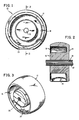
- the intake spherical drum 10 is defined by an arcuate spherical circumferential periphery 12 and planer sidewall 14 and planer wall 16, opposite planer sidewall 14 which is parallel to sidewall 14 with the intersecting edges of planer sidewall 16 and 14 with arcuate spherical circumferential periphery 12 being rounded off.
- the arcuate extension of circumferential periphery 12 as shown in the side cross sectional view Figure 1 would define a circle.
- centrally-disposed inwardly from planer sidewall 16 is an annular U-shaped or doughnut cavity cavity 18 which extends from planer sidedwall 16 to a depth approximate to planer sidewall 14. The corners and edges of U-shaped cavity 18 are preferably machined such that they are rounded.
- intake spherical drum 10 Centrally disposed through intake spherical drum 10, a central aperture 20 extending from planer sidewall 16 through to planer sidewall 14, aperture 20 being centrally disposed through intake spherical drum 10.
- Centrally disposed aperture 20 provides the means for mounting intake spherical drum 10 on the centrally disposed shaft 22 to provide for the rotational disposition of intake spherical drum 10 as further described hereafter.
- aperture 20 and shaft 22 are shown longitudinally threaded; however, other mounting means as described hereafter are suitable.
- Intake aperture 24 Passing through arcuate spherical circumferential periphery 12 and providing communication with annular U-shaped or doughnut cavity 18 is an intake aperture 24.
- Intake aperture 24 is circular in cross sectional area and is designed to communicate with the inlet port of the cylinder during the rotational disposition of spherical intake drum 10 as described hereafter.
- the intersecting edge of intake aperture 24 and its intersection with arcuate circumferential periphery 12 is machined to a rounded radius.
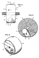
- Exhaust spherical drum 30 has a arcuate spherical circumferential periphery 32 and planer parallel sidewalls 34 and 36 intersecting with arcuate spherical circumferential periphery 32, the edges of such intersection preferably being rounded.
- Exhaust spherical drum 30 has disposed centrally therethrough, from planer sidewall 36 to planer sidewall 34, a centrally disposed aperture 38 for the mounting of exhaust sperical drum 30 on shaft 22 for the rotational-disposition of exhaust spherical drum 30 as described hereafter.
- Exhaust spherical drum 30 has defined therethrough, an exhaust conduit 40 defined by a first exhaust aperture 42, substantially circular in cross sectional area and positioned on arcuate circumferential periphery 32 of exhaust spherical drum 30 and a second exhaust port aperture 44 positioned on planer sidewall 34 of exhaust spherical drum 30.
- Exhaust aperture 42 is designed for alignment with the exhaust port of the cylinder as described hereafter
- exhaust port 44 is designed for alignment with the exhaust manifold, the conduit between exhaust ports 42 and 44 providing for the means for escape or evacuation of exhaust gases from the cylinder as described hereafter.
- the intake spherical drum 10 has U-shaped or doughnut cavity 18 in constant communication with the incoming fuel-air mixture from the carburetor and this fuel-air mixture in U-shaped or doughnut cavity 18 is introduced into the cylinder when inlet aperture 24 comes into rotational alignment with the inlet port in the lower half of the cylinder head.
- arcuate circumferential periphery 12 serves to seal the inlet port of the cylinder.
- the arcuate circumferential periphery 32 of exhaust spherical drum 30 maintains a seal on the exhaust port of the cylinder until first exhaust Port 42 on arcuate circumferential periphery 32 of exhaust spherical drum 30 comes into rotational alignment with the exhaust port of the cylinder positioned in the lower half of the cylinder head.
- the exhaust stroke of the piston then forces the evacuation of the gases through first exhaust port 42 and internal conduit 40 to second exhaust port 44 and thence to the exhaust manifold.
- intake aperture 24 on intake spherical drum 10 and first exhaust port 42 on exhaust spherical drum 30 is done with consideration with respect to the power strokes and exhaust strokes of the piston within the cylinder and the timing requirements of the engine.
- FIG. 7 there is shown a side sectional view of the cylinder and cylinder head with internal piston in conjunction with the intake spherical drum.
- the cylinder and piston and block are similar to that of a conventional internal combustion engine.
- an engine block 100 having disposed therein, a cylinder cavity 102 there being positioned within cylinder cavity 102, a reciprocating piston 104 which is secured to a crankshaft 103 and which moves in a reciprocating action within cylinder cavity 102.
- the cylinder cavity itself is surrounded by a plurality of enclosed passageways 106 designed to permit the passage therethrough of a cooling fluid to maintain the temperature of the engine.
- Applicant's engine head is a split head comprising a first lower section 110 which is secured to the engine block 100 and contains an intake port 108 for cylinder 102.
- Intake port 108 is positioned in a hemispherical drum accommodating cavity 107 defined by the intersection of two perpendicular parallel planes in order to accommodate the positioning of intake spherical drum 10.
- the upper half 112 of the split head assembly also contains a hemispherical drum accommodating cavity 113 defined by the intersection of two parallel planes in order to define a cavity for receipt of the upper half of intake spherical drum 10.
- intake spherical drum 10 is rotationally encapsulated within the cavity defined by the two halves of the split head assembly. See Figures 9 and 10 for a perspective view of the split head drum relationship.
- U-shaped or doughnut cavity 18 is in communication with the inlet port 114 to permit the fuel-air mixture to flow into U-shaped or doughnut cavity 18.
- a sealing mechanism 116 as described hereafter, is positioned about inlet port 108 to cylinder cavity 102 in order to provide an effective seal during the rotational disposition of intake spherical drum 10.
- Lower and upper section 110 and 112 of the head also contain a plurality of interior passageways 106 to provide for the passage of cooling fluid. Appropriate oil ducts can also be provided for lubrication.
- intake spherical drum 10 is emphasized. Directly behind intake spherical drum 10 would be exhaust spherical drum 30 whose operation with respect to the piston will be disclosed hereafter.
- U-shaped or doughnut cavity 18 on intake spherical drum 10 is continually charged with a fuel-air mixture through inlet port 114.
- This fuel-air mixture is not introduced into cylinder cavity 102 until intake aperture 24 comes into rotational alignment with inlet port 108.
- Sealing mechanism 116 cooperates with the arcuate circumferential periphery 12 of intake spherical drum 10 to provide an effective gas tight seal to ensure that the fuel-air mixture passes from U-shaped or doughnut cavity 18 through inlet port 108 and into cylinder cavity 102. In normal operation, this introduction occurs with the downward movement of piston 104 during the intake stroke thus charging the cylinder with a fuel-air mixture.
- an engine block 100 having a cylinder cavity 102 disposed therein, with a reciprocating piston 104 within the cylinder cavity 102.
- Lower and upper heads 110 and 112 are secured to the engine block 100 and in this figure, the exhaust spherical drum 30 is disclosed.
- Exhaust spherical drum 30 is rotationally disposed within lower half and upper half 110 and 112 of the split head assembly in a drum accommodating cavity 107 and 113 similar to intake spherical drum 10 and is in communication with an exhaust port 109 for cylinder cavity 102.
- the piston 104 has completed its power stroke, thus compressing and igniting the fuel-air mixture within the cylinder.
- This power stroke is accomplished with the arcuate spherical circumferential periphery of intake spherical drum 10 and exhaust spherical drum 30 providing the required sealing closure of the respective inlet port 108 and exhaust port 109.
- the ignition of the fuel-air mixture serves to drive piston 104 downwardly within cylinder cavity 102 and thence, piston 104 begins its ascent in the exhaust stroke.
- Exhaust spherical drum 30 rotating with shaft 22 and in timing communication with the crankshaft rotates to bring first exhaust port 42 in communication with exhaust port 109.
- a conduit passageway is defined through exhaust spherical drum 30 from exhaust port 109 at the top of the cylinder head, to first exhaust aperture 42 on arcuate spherical circumferential periphery 32 of exhaust spherical drum 30, and thence through interior conduit 40 to second exhaust port 44 on the sidewall of exhaust spherical drum 30 and thence through exhaust conduits 120, the exhaust gases being evacuated to the ambient atmosphere.
- Exhaust spherical drum 30 continues its rotation such that first exhaust aperture 42 is rotated out of alignment with exhaust port 109 thus sealing cylinder cavity 102 proximate to piston 104's topmost ascent, at which point, the inlet aperture 24 on intake spherical drum 10 would be coming into rotational alignment with inlet port 108 for the introduction of fresh fuel-air mixture charge.
- Exhaust spherical drum 30 is in contact with the sealing means 116 identical to the sealing means utilized with respect to intake spherical drum 10 and described hereafter.
- FIG. 9 there is shown a perspective view of the rotary spherical valve assembly mounted on shaft 22 for utilization in a four-cylinder engine.
- This figure shows paired relationship of intake spherical drum 10 and exhaust spherical drum 30 with respect to each cylinder in a four-cylinder engine.
- Figure 10 is a perspective view of the rotary spherical valve assembly positioned within lower section 110 of the split head assembly with respect to a single cylinder.
- Figures 9 and 10 serve to show the relationship between the intake spherical drum 10 and the exhaust spherical drum 30 in positioning the spherical rotary valve assembly in the split head.
- gear means 121 Positioned at one end of shaft 22 is gear means 121 which is in communication with the crankshaft of the engine by means of a timing chain or belt in order to synchronize the rotation of the rotary spherical valve assembly with respect to the movement of the pistons within the cylinder. It will be recognized by one skilled in the art, that if a V-8 engine were utilized, each bank of cylinders would have one spherical rotary valve assembly associated therewith.
- Spherical drums, 10 and 30 are machined as is the drum accommodating cavities 107 and 113, the tolerance between the spherical drums and the cavity being approximately one thousandth of an inch.
- shaft 22 and the spherical drum assembly When shaft 22 and the spherical drum assembly is positioned within the split head, shaft 22 contact bearing surfaces 130 and spherical drums 10 and 30 respectively are in contact only with sealing means 116, the embodiments of which are described hereafter.
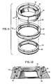
- FIG 11 there is shown a perspective explosed view of, a first embodiment of sealing mechanism 116 which is positioned within lower section 110 of the split head assembly.
- Figure 12 is a cutaway side view of sealing mechanism 116.
- Lower section 110 of the split head assembly has an inlet port 108 and an outlet port 109 machined therein for communication with cylinder cavity 102.
- Circumferentially disposed about inlet port 108 or exit port 109 is a circumferential, machined annular indent 140 whose cross sectional area resembles an inverted L-shape.
- Sealing means 116 is inserted into this indent, sealing means 116 comprising a concave circular seal 142 whose upper surface 144 is concave shaped to conform to the spherical configuration of the chamber within lower section 110 of the split head assembly in order to conform to the annular, spherical circumferential periphery of either intake spherical drum 10 or exhaust spherical drum 30.
- the lower portion of seal 142 comprises a downwardly depending annular leg 146 and a shoulder portion 148 designed to conform to the shape of annular indent 140.
- Beveled pressure springs 150 are positioned below depending leg 146 and shoulder 148 so as to provide a resilient compression to seal 142 in order to ensure intimate contact with the annular spherical circumferential periphery of intake spherical drum 10 or exhaust spherical drum 30. Beveled springs 150 ensure that upper surface 144 of seal 142 maintains contact with the arcuate spherical circumferential periphery of the intake or exhaust spherical drum.
- the upward pressure provided by springs 150 is normally in the range of 1-5 ounces to insure gas tight sealing contact.
- the upper surface 144 of seal 142 is slightly arcuate in nature in order to conform with the arcuate spherical circumferential periphery of the intake or exhaust spherical drum 10 or 30 in order to ensure that a secure seal is maintained.
- Upper surface 144 may have one or more grooves 143 to assist in this sealing contact.
- Figure 13 is a perspective exploded view of a second embodiment of a sealing ring and Figure 14 is a cross sectional view of the second embodiment of the sealing ring.
- the sealing mechanism is positioned within lower section 110 of the split head assembly.
- Lower section 110 of split head assembly has positioned about the inlet port 108 or the outlet port 109, a plurality of circumferential indents 150.
- Disposed within indents 150 are circular seals 152 which have positioned below them in indents or grooves 150, either bevel springs or wave springs 154 in order to produce an upward resilient pressure on the seal 152 to maintain contact with intake spherical drum 10 or exhaust sperical drum 30.
- Seals 152 have incline sidewalls in order to conform to annular indents 150 which are perpendicular to the drum accommodating cavity 107. In this configuration, the center line of seal 152, if extended, would intersect the central axis of intake spherical drum 10 or exhaust spherical drum 30.
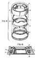
- FIG. 15 there is shown an exploded perspective view of a third embodiment of a sealing ring and Figure 16 which is a cross sectional view of the third embodiment of the sealing ring.
- the third embodiment of the sealing means 116 is again positioned within an annular indent 160 about the inlet port or the outlet port of lower half 110 of the split head assembly.
- the third embodiment of the sealing ring, 162 has an upper surface 164 which is arcuate in order to conform to the surface of the drum accommodating cavity and contact the intake spherical drum 10 or exhaust spherical drum 30.
- Sealing ring 162 has an annular indent 166 in lower end 168 in order to accommodate a pressure ring 170.
- Pressure ring 170 fits into indent 166 and has a wave spring or bevel spring 172 Positioned in its indent or groove. Positioned about lower portion 168 of sealing ring 162 are another pair of either beveled or waved springs 174 in order to maintain an upward pressure on sealing ring 162 so that upper surface 164 maintains contact with intake spherical drum 10 or exhaust spherical drum 30. Upper surface 164 may have one or more grooves in its surface to aid in the sealing contact with intake drum 10 or exhause drum 30.
- Applicant's embodiment as disclosed herein shows spherical intake and exhaust drums mounted on a splined shaft 22.
- Splined shaft 22 would have a space to slidable bearing surface positioned thereon in order to contact bearing surfaces 130 with respect to the split head assembly.
- the spherical intake and exhaust drums 10 and 30 could be mounted on shaft 22 by means of another method.
- the embodiment shown discloses intake and exhaust spherical drums 10 and 30 mounted on a single shaft 22.
- a multi-shaft mounting method could be incorporated whereby the intake spherical drums 10 are mounted on a first shaft and the exhaust spherical drums 30 are mounted on a second shaft within a split head assembly and within drum accommodating cavities within the split head.
- the operation of the spherical valve assembly would be identical to that disclosed herein with the exception that the exhaust drums would rotate on a separate shaft from the intake drums which would permit redesign or alignment of the inlet port providing the fuel-air mixture to intake spherical drum 10 and the exhaust conduit evacuating the exhaust gases from exhaust spherical drum 30.
- the embodiment disclosed herein is with respect to a four-cycle engine.
- Applicant's invention would provide the advantages of multi-valve engines which have multiple intake and exhaust valves per cylinder. This permits shaft 22 to rotate at an arithmetically progressive lower revolutions per minute than the crankshaft providing less wear and tear on the engine.
Landscapes
- Engineering & Computer Science (AREA)
- Mechanical Engineering (AREA)
- General Engineering & Computer Science (AREA)
- Cylinder Crankcases Of Internal Combustion Engines (AREA)
- Taps Or Cocks (AREA)
- Valve-Gear Or Valve Arrangements (AREA)
- Joints Allowing Movement (AREA)
- Combustion Methods Of Internal-Combustion Engines (AREA)
Claims (12)
- Assemblage de soupape rotative sphérique utilisable dans les moteurs à combustion interne du type piston et cylindre, cet assemblage de soupape rotative sphérique comprenant :
une tête de cylindre formée de deux pièces amovible fixable au moteur à combustion interne, cette tête de cylindre amovible formée de deux pièces comprenant une section de tête de cylindre supérieure et inférieure (112, 110), cette section de tête de cylindre supérieure et inférieure lorsque fixée au moteur à combustion interne (100) définissant une cavité (113, 107) dans l'alignement radial des cylindres (102) de ce moteur à combustion interne, cette cavité définissant une première cavité de réception de tambour et une seconde cavité de réception de tambour pour chacun des cylindres du moteur à combustion interne, la section de tête de cylindre inférieure (110) et la première cavité de réception de tambour comportant un orifice d'entrée (108) en communication avec ledit cylindre, la section de tête de cylindre inférieure (110) et la seconde cavité de réception de tambour comportant un orifice de sortie (109) en communication avec ledit cylindre, un moyen d'étanchéité (116) associé aux orifices d'entrée et de sortie précités, un premier passage (114) pour l'introduction d'un mélange de carburant/air dans la tête de cylindre par l'intermédiaire de la première cavité de réception de tambour (107) et un second passage (120) pour l'évacuation des gaz d'échappement dudit cylindre par l'intermédiaire de la seconde section de réception de tambour (113), un moyen d'arbre (22) tourillonné sur des surfaces de support (130) à l'intérieur de la cavité de la tête de cylindre formée de deux pièces amovible, l'arbre (22) comportant un premier tambour (10) dans la première cavité de réception de tambour et un second tambour (30) dans la seconde cavité de réception de tambour pour chacun de ces cylindres, chaque tambour comportant une section sphérique définie par deux plans parallèles d'une sphère, les plans étant disposés symétriquement autour du centre de ladite sphère, l'intersection entre les plans et la section sphérique étant arrondie définissant un tambour ayant une périphérie sphérique (12) et des parois d'extrémité plus plates (14, 16), le moyen d'arbre (22) susdit occupant la surface de support tourillonnée (130) dans ladite cavité en contact de scellage étanche aux gaz, chacun desdits tambours (10, 30) occupant la cavité de réception de tambour (113, 107) en contact de scellage étanche aux gaz avec l'orifice d'entrée (108) et l'orifice de sortie (109) dans la section de tête de cylindre inférieure (110) et en isolement l'un par rapport à l'autre, le premier tambour (10) interrompant le premier passage (114) pour l'introduction du mélange de carburant/air au moteur et le second tambour (30) interrompant le second passage (120) pour l'évacuation des gaz d'échappement du moteur, dans lequel le moyen d'arbre (21) et les tambours (10, 30) sont entraînés en rotation à une vitesse liée au cycle de fonctionnement du moteur de telle sorte que le premier tambour (10) entre successivement en contact avec l'orifice d'entrée (108) dudit cylindre et le premier passage (114) pour transférer des charges successives de mélange de carburant/air au cylindre au cours de la rotation de l'arbre et le second tambour (30) entre successivement en contact avec l'orifice de sortie (109) dudit cylindre et le second passage (120) pour évacuer des charges successives de gaz d'échappement du cylindre au cours de la rotation de l'arbre, caractérisé en ce que le premier tambour (10) dans la première cavité de réception de tambour comprend un évidement torique (18) sur le côté plus plat (16) en contact continu avec le premier passage (114) pour l'introduction du mélange de carburant/air, le premier tambour (10) comportant au moins une ouverture (24) sur sa périphérie sphérique (12) en communication avec l'évidement torique (18) pour un alignement successif par rotation sur l'orifice d'entrée (108) dudit cylindre pour l'introduction du mélange de carburant et d'air. - Assemblage de soupape rotative sphérique suivant la revendication 1, caractérisé en ce que le second tambour (30) comprend au moins une ouverture (42) sur sa périphérie sphérique (32) pour un alignement par rotation successif sur l'orifice de sortie (109) du cylindre susdit, le second tambour (30) comportant un passage de dégagement (40) en communication avec au moins une seconde ouverture (44) sur la surface latérale plus plate (34) du second tambour pour un alignement successif sur le second passage (120), le passage (40) dans le second tambour (30) pour un alignement par rotation successif sur l'orifice de sortie (109) dudit cylindre et le second passage (40) pour l'évacuation des gaz d'échappement de ce cylindre.
- Assemblage de soupape rotative sphérique suivant la revendication 1, caractérisé en ce que la rotation du moyen d'arbre (22) et du premier tambour (10) amène la charge de mélange de carburant en communication avec le cylindre (102) au cours de la course d'aspiration du piston (104), la périphérie sphérique (12) et le moyen d'étanchéité (116) constituant le joint étanche aux gaz pour l'orifice d'entrée (108) du cylindre jusqu'à la course d'aspiration suivante et le second tambour (30) reçoit une charge de gaz d'échappement comprimés du cylindre (102) au cours de la course d'échappement, la périphérie sphérique (32) et le moyen d'étanchéité (116) constituant le joint étanche aux gaz pour l'orifice de sortie (109) du cylindre (102) jusqu'à la course d'échappement suivante.
- Assemblage de soupape rotative sphérique suivant la revendication 1, caractérisé en ce que le contact de scellage étanche aux gaz du premier tambour (10) et du second tambour (30) dans la cavité de réception de tambour précitée comprend un joint annulaire (142) aligné axialement respectivement dans lesdites cavités de réception de tambour sur l'orifice d'entrée (108) et l'orifice de sortie (109) du cylindre (102), ledit joint annulaire (142) étant positionné dans un évidement annulaire (140) autour de l'orifice d'entrée ou de l'orifice de sortie précité dans lesdites cavités de réception de tambour, ce joint annulaire (142) comportant positionné en dessous de celui-ci dans l,évidement annulaire (140), un moyen (150) pour exercer une pression vers le haut sur ledit joint de manière à maintenir un contact de scellage étanche aux gaz avec la périphérie sphérique (12; 32) du tambour (10; 30).
- Assemblage de soupape rotative sphérique suivant la revendication 4, caractérisé en ce que le moyen pour exercer une pression vers le haut sur le joint susdit de manière à maintenir un contact de scellage étanche aux gaz avec la périphérie sphérique du tambour comprend un moyen de rappel (150) sous la forme d'un ressort ondulé ou d'un ressort conique (150) positionné dans l'évidement en dessous du joint annulaire.
- Assemblage de soupape rotative sphérique suivant la revendication 4, caractérisé en ce que la surface supérieure (144) du joint annulaire (142) est concave afin de se conformer à la courbure de la périphérie sphérique du tambour pour réaliser le joint étanche aux gaz.
- Assemblage de soupape rotative sphérique suivant la revendication 1, caractérisé en ce que le moyen d'arbre (22) comprend un seul arbre ou rotor tourillonné sur une surface de support à l'intérieur de la cavité de la tête de cylindre formée de deux pièces amovible (112, 110), le premier tambour (10) et le second tambour (30) étant positionnés sur cet arbre ou rotor.
- Assemblage de soupape rotative sphérique suivant la revendication 1, caractérisé en ce que le moyen d'arbre (22) comprend un premier arbre et un second arbre alignés axialement parallèlement à l'intérieur de la tête de cylindre formée de deux pièces (112, 110), les premiers tambours (10) dans les premières cavités de réception de tambour pour l'introduction du mélange de carburant/air dans le moteur étant montés sur ce premier arbre, les seconds tambours (30) dans les secondes cavités de réception de tambour, pour l'évacuation de charges successives de gaz d'échappement du cylindre, étant montés sur le second arbre.
- Assemblage de soupape rotative sphérique suivant l'une ou l'autre des revendications 1 et 2, caractérisé en ce que le premier tambour (10) comportant une seule ouverture (24) sur sa périphérie sphérique (12) tourne sur le moyen d'arbre précité à la moitié des tours du moteur.
- Assemblage de soupape rotative sphérique suivant l'une ou l'autre des revendications 1 et 2, caractérisé en ce que le premier tambour (10) comporte une pluralité d'ouvertures sur sa périphérie sphérique (12) permettant l'enclenchement ou le réglage de ce premier tambour (10) de manière à tourner à un nombre de tours inférieur à celui du moteur sur la base de la progression arithmétique du nombre précité de passages.
- Assemblage de soupape rotative sphérique suivant l'une ou l'autre des revendications 1 et 2, caractérisé en ce que le second tambour (30) comprend un seul passage (40) partant d'une première ouverture (42) sur la périphérie sphérique (32) vers la seconde ouverture (44) sur la surface latérale plus plate (34) pour permettre la rotation de ce second tambour à la moitié de la vitesse de révolution du moteur.
- Assemblage de soupape rotative sphérique suivant l'une ou l'autre des revendications 1 et 2, caractérisé en ce que le second tambour (30) comporte une pluralité de passages partant d'une pluralité de premières ouvertures (42) sur la périphérie sphérique (32) vers une pluralité de secondes ouvertures (44) sur la surface latérale plus plate (34) permettant l'enclenchement et le réglage de ce second tambour (30) de manière à tourner à un nombre de tours inférieur à celui du moteur sur la base de la progression arithmétique du nombre précité de passages.
Priority Applications (1)
| Application Number | Priority Date | Filing Date | Title |
|---|---|---|---|
| AT89105373T ATE85671T1 (de) | 1988-11-14 | 1989-03-25 | Anordnung eines sphaerischen drehventils fuer eine brennkraftmaschine. |
Applications Claiming Priority (2)
| Application Number | Priority Date | Filing Date | Title |
|---|---|---|---|
| US07/270,037 US4953527A (en) | 1988-11-14 | 1988-11-14 | Spherical rotary valve assembly for an internal combustion engine |
| US270037 | 1994-07-01 |
Publications (2)
| Publication Number | Publication Date |
|---|---|
| EP0369099A1 EP0369099A1 (fr) | 1990-05-23 |
| EP0369099B1 true EP0369099B1 (fr) | 1993-02-10 |
Family
ID=23029626
Family Applications (1)
| Application Number | Title | Priority Date | Filing Date |
|---|---|---|---|
| EP89105373A Expired - Lifetime EP0369099B1 (fr) | 1988-11-14 | 1989-03-25 | Ensemble de soupape rotative sphérique pour moteur à combustion interne |
Country Status (11)
| Country | Link |
|---|---|
| US (1) | US4953527A (fr) |
| EP (1) | EP0369099B1 (fr) |
| JP (1) | JP2698812B2 (fr) |
| KR (1) | KR950003061B1 (fr) |
| AT (1) | ATE85671T1 (fr) |
| AU (1) | AU615997B2 (fr) |
| CA (1) | CA1329781C (fr) |
| DE (1) | DE68904878T2 (fr) |
| ES (1) | ES2038356T3 (fr) |
| GR (1) | GR3007284T3 (fr) |
| HK (1) | HK35894A (fr) |
Families Citing this family (34)
| Publication number | Priority date | Publication date | Assignee | Title |
|---|---|---|---|---|
| US4944261A (en) * | 1989-10-16 | 1990-07-31 | Coates George J | Spherical rotary valve assembly for an internal combustion engine |
| US5249553A (en) * | 1991-04-30 | 1993-10-05 | Guiod James J | Rotary valve shaft indent system |
| US5109814A (en) * | 1991-05-10 | 1992-05-05 | Coates George J | Spherical rotary valve |
| US5361739A (en) * | 1993-05-12 | 1994-11-08 | Coates George J | Spherical rotary valve assembly for use in a rotary valve internal combustion engine |
| US5535715A (en) * | 1994-11-23 | 1996-07-16 | Mouton; William J. | Geared reciprocating piston engine with spherical rotary valve |
| DE19519031C2 (de) * | 1995-05-24 | 1999-07-01 | Arno Hofmann | Drehschiebereinrichtung für einen Kolbenmotor |
| US5724926A (en) * | 1995-12-22 | 1998-03-10 | Eagle Heads, Ltd. | Rotary valve assembly for an internal combustion engine |
| US5738051A (en) * | 1996-03-06 | 1998-04-14 | Outboard Marine Corporation | Four-cycle marine engine |
| US5711265A (en) * | 1996-07-22 | 1998-01-27 | Duve; Donald A. | Rotary valve drive mechanism |
| US5623901A (en) * | 1996-08-14 | 1997-04-29 | Hartzell; Mark E. | Time twister cylinder head for use in internal combustion engines |
| US5967108A (en) | 1996-09-11 | 1999-10-19 | Kutlucinar; Iskender | Rotary valve system |
| US5931134A (en) * | 1997-05-05 | 1999-08-03 | Devik International, Inc. | Internal combustion engine with improved combustion |
| US6029617A (en) * | 1998-05-12 | 2000-02-29 | Lambert; Steven | Modular rotary discoid valve assembly for engines and other applications |
| US6158465A (en) * | 1998-05-12 | 2000-12-12 | Lambert; Steven | Rotary valve assembly for engines and other applications |
| RU2177552C2 (ru) * | 2000-03-06 | 2001-12-27 | Шакиров Мубарак Шакирович | Газораспределительный механизм с тороидальной камерой двигателя внутреннего сгорания |
| US6415756B1 (en) | 2000-07-20 | 2002-07-09 | Jung W. Lee | Spherical rotary engine valve |
| US6578538B2 (en) | 2001-04-02 | 2003-06-17 | O. Paul Trentham | Rotary valve for piston engine |
| US6666458B2 (en) * | 2002-02-12 | 2003-12-23 | George J. Coates | Valve seal for rotary valve engine |
| US6718933B1 (en) * | 2002-10-28 | 2004-04-13 | George J. Coates | Valve seal for rotary valve engine |
| US6789516B2 (en) * | 2003-01-07 | 2004-09-14 | George J. Coates | Rotary valve and valve seal assembly for rotary valve engine having hemispherical combustion chambers |
| US8342204B2 (en) * | 2006-12-28 | 2013-01-01 | Perkins Engines Company Limited | Rotary valve for use in an internal combustion engine |
| US7721689B2 (en) * | 2006-12-28 | 2010-05-25 | Perkins Engines Company Limited | System and method for controlling fluid flow to or from a cylinder of an internal combustion engine |
| US8100102B2 (en) * | 2006-12-28 | 2012-01-24 | Perkins Engines Company Limited | Cylinder head for an internal combustion engine |
| US7802550B2 (en) * | 2006-12-28 | 2010-09-28 | Caterpillar Inc | Cylinder head arrangement including a rotary valve |
| US7591240B2 (en) * | 2006-12-28 | 2009-09-22 | Perkins Engines Company Limited | Method for providing a mixture of air and exhaust |
| US7926461B2 (en) * | 2006-12-28 | 2011-04-19 | Perkins Engines Company Limited | System for controlling fluid flow |
| US8100144B2 (en) * | 2006-12-28 | 2012-01-24 | Perkins Engines Company Limited | Mounting arrangement for a rotary valve |
| US7802551B2 (en) * | 2006-12-28 | 2010-09-28 | Perkins Engines Company Ltd | Cylinder head for an internal combustion engine |
| FR2994250B1 (fr) * | 2012-08-03 | 2014-09-05 | Snecma | Chambre de combustion cvc pour turbomachine d'aeronef comprenant une valve d'admission / d'echappement a tournant spherique |
| US9903239B2 (en) * | 2015-01-29 | 2018-02-27 | Vaztec Engine Venture, Llc | Engine with rotary valve apparatus |
| US20160222839A1 (en) * | 2015-01-29 | 2016-08-04 | Vaztec, Llc | Seal apparatus for rotary valve engine |
| IL255916B (en) | 2017-11-26 | 2020-08-31 | Yacob Rafaeli | Rotary valve assembly for an engine head in an internal combustion engine |
| US11976730B2 (en) * | 2020-11-13 | 2024-05-07 | Mainspring Energy, Inc. | Manifold interface seal |
| WO2022256890A1 (fr) * | 2021-06-09 | 2022-12-15 | Tavares Diego | Mécanisme de commande d'entrée de mélange air/combustible et de sortie de gaz par un axe transversal de commande |
Family Cites Families (12)
| Publication number | Priority date | Publication date | Assignee | Title |
|---|---|---|---|---|
| GB191323123A (en) * | 1913-10-13 | 1914-10-13 | Harold Wade | Improvements in or relating to Valves for Internal Combustion Engines. |
| FR507701A (fr) * | 1918-12-28 | 1920-09-22 | Andre Leon Pierre Gueret | Perfectionnements apportés aux moteurs à combustion interne à distributeur cylindrique |
| CA931045A (en) * | 1970-05-29 | 1973-07-31 | R. Deane William | Rotary valve |
| JPS5187613A (en) * | 1975-01-29 | 1976-07-31 | Hidekane Konishi | Reshipurogata 44 saikuruenjinnitekyosarerurootariibarubusochi |
| US4077382A (en) * | 1975-10-06 | 1978-03-07 | Gentile Carl A | Rotary valve for internal combustion engines |
| US4019487A (en) * | 1975-11-26 | 1977-04-26 | Dana Corporation | Rotary valve seal assembly |
| JPS5431818A (en) * | 1977-08-17 | 1979-03-08 | Sunao Igarashi | Rotary valve engine |
| IE811742L (en) * | 1981-07-30 | 1983-01-30 | George Coates | Internal combustion engine having rotary inlet and exhaust¹valves |
| US4989576A (en) * | 1981-07-30 | 1991-02-05 | Coates George J | Internal combustion engine |
| JPS6251706A (ja) * | 1985-08-30 | 1987-03-06 | Honda Motor Co Ltd | 内燃機関の摺動弁のシ−ル構造 |
| JPS6278416A (ja) * | 1985-09-30 | 1987-04-10 | Honda Motor Co Ltd | 内燃機関における回転弁のシ−ル装置 |
| DE3633259A1 (de) * | 1985-09-30 | 1987-05-14 | Honda Motor Co Ltd | Drehventileinrichtung fuer brennkraftmaschinen |
-
1988
- 1988-11-14 US US07/270,037 patent/US4953527A/en not_active Expired - Lifetime
- 1988-12-23 CA CA000587023A patent/CA1329781C/fr not_active Expired - Lifetime
-
1989
- 1989-03-25 EP EP89105373A patent/EP0369099B1/fr not_active Expired - Lifetime
- 1989-03-25 AT AT89105373T patent/ATE85671T1/de not_active IP Right Cessation
- 1989-03-25 ES ES198989105373T patent/ES2038356T3/es not_active Expired - Lifetime
- 1989-03-25 DE DE8989105373T patent/DE68904878T2/de not_active Expired - Lifetime
- 1989-03-30 AU AU32228/89A patent/AU615997B2/en not_active Expired
- 1989-05-15 JP JP1118839A patent/JP2698812B2/ja not_active Expired - Lifetime
- 1989-06-14 KR KR1019890008169A patent/KR950003061B1/ko not_active Expired - Lifetime
-
1993
- 1993-03-09 GR GR930400507T patent/GR3007284T3/el unknown
-
1994
- 1994-04-14 HK HK35894A patent/HK35894A/en not_active IP Right Cessation
Also Published As
| Publication number | Publication date |
|---|---|
| AU3222889A (en) | 1990-05-17 |
| JP2698812B2 (ja) | 1998-01-19 |
| DE68904878T2 (de) | 1993-05-27 |
| KR950003061B1 (ko) | 1995-03-30 |
| AU615997B2 (en) | 1991-10-17 |
| DE68904878D1 (de) | 1993-03-25 |
| GR3007284T3 (fr) | 1993-07-30 |
| KR900008147A (ko) | 1990-06-02 |
| ES2038356T3 (es) | 1993-07-16 |
| CA1329781C (fr) | 1994-05-24 |
| EP0369099A1 (fr) | 1990-05-23 |
| US4953527A (en) | 1990-09-04 |
| ATE85671T1 (de) | 1993-02-15 |
| HK35894A (en) | 1994-04-22 |
| JPH02136503A (ja) | 1990-05-25 |
Similar Documents
| Publication | Publication Date | Title |
|---|---|---|
| US4953527A (en) | Spherical rotary valve assembly for an internal combustion engine | |
| US4989558A (en) | Spherical rotary valve assembly for an internal combustion engine | |
| CA2115502C (fr) | Soupape rotative spherique pour moteur a combustion interne a soupapes rotatives | |
| EP0423444B1 (fr) | Soupapes rotatives sphériques pour moteur à combustion interne | |
| US5109814A (en) | Spherical rotary valve | |
| US4989576A (en) | Internal combustion engine | |
| US6779504B2 (en) | Spherical rotary intake valve for spherical rotary valve engine assembly | |
| US5410996A (en) | Rotary valve assembly used with reciprocating engines | |
| US5878707A (en) | Rotary valve internal combustion engine | |
| EP0933500A1 (fr) | Machine volumétrique à piston rotatif | |
| US4867117A (en) | Rotary valve with integrated combustion chamber | |
| US5595154A (en) | Rotary engine | |
| US6595177B1 (en) | Rotary sleeve port for an internal combustion engine | |
| GB1592279A (en) | Internal combustion rotary engines | |
| GB2225056A (en) | I.C. engine | |
| AU696388B2 (en) | Rotary valve for internal combustion engine | |
| GB2293210A (en) | Engine or compressor rotary valve arrangement | |
| GB2235014A (en) | I.c engine cylinder |
Legal Events
| Date | Code | Title | Description |
|---|---|---|---|
| PUAI | Public reference made under article 153(3) epc to a published international application that has entered the european phase |
Free format text: ORIGINAL CODE: 0009012 |
|
| AK | Designated contracting states |
Kind code of ref document: A1 Designated state(s): AT BE CH DE ES FR GB GR IT LI LU NL SE |
|
| 17P | Request for examination filed |
Effective date: 19900409 |
|
| 17Q | First examination report despatched |
Effective date: 19910912 |
|
| GRAA | (expected) grant |
Free format text: ORIGINAL CODE: 0009210 |
|
| AK | Designated contracting states |
Kind code of ref document: B1 Designated state(s): AT BE CH DE ES FR GB GR IT LI LU NL SE |
|
| REF | Corresponds to: |
Ref document number: 85671 Country of ref document: AT Date of ref document: 19930215 Kind code of ref document: T |
|
| REF | Corresponds to: |
Ref document number: 68904878 Country of ref document: DE Date of ref document: 19930325 |
|
| ET | Fr: translation filed | ||
| ITF | It: translation for a ep patent filed | ||
| REG | Reference to a national code |
Ref country code: GR Ref legal event code: FG4A Free format text: 3007284 |
|
| REG | Reference to a national code |
Ref country code: ES Ref legal event code: FG2A Ref document number: 2038356 Country of ref document: ES Kind code of ref document: T3 |
|
| PLBE | No opposition filed within time limit |
Free format text: ORIGINAL CODE: 0009261 |
|
| STAA | Information on the status of an ep patent application or granted ep patent |
Free format text: STATUS: NO OPPOSITION FILED WITHIN TIME LIMIT |
|
| 26N | No opposition filed | ||
| EPTA | Lu: last paid annual fee | ||
| EAL | Se: european patent in force in sweden |
Ref document number: 89105373.8 |
|
| REG | Reference to a national code |
Ref country code: GB Ref legal event code: IF02 |
|
| PGFP | Annual fee paid to national office [announced via postgrant information from national office to epo] |
Ref country code: CH Payment date: 20080320 Year of fee payment: 20 Ref country code: ES Payment date: 20080326 Year of fee payment: 20 |
|
| PGFP | Annual fee paid to national office [announced via postgrant information from national office to epo] |
Ref country code: GB Payment date: 20080318 Year of fee payment: 20 Ref country code: LU Payment date: 20080320 Year of fee payment: 20 Ref country code: SE Payment date: 20080320 Year of fee payment: 20 |
|
| PGFP | Annual fee paid to national office [announced via postgrant information from national office to epo] |
Ref country code: AT Payment date: 20080319 Year of fee payment: 20 |
|
| PGFP | Annual fee paid to national office [announced via postgrant information from national office to epo] |
Ref country code: DE Payment date: 20080318 Year of fee payment: 20 Ref country code: FR Payment date: 20080314 Year of fee payment: 20 |
|
| PGFP | Annual fee paid to national office [announced via postgrant information from national office to epo] |
Ref country code: BE Payment date: 20080321 Year of fee payment: 20 |
|
| PGFP | Annual fee paid to national office [announced via postgrant information from national office to epo] |
Ref country code: IT Payment date: 20080329 Year of fee payment: 20 |
|
| PGFP | Annual fee paid to national office [announced via postgrant information from national office to epo] |
Ref country code: NL Payment date: 20080318 Year of fee payment: 20 |
|
| PGFP | Annual fee paid to national office [announced via postgrant information from national office to epo] |
Ref country code: GR Payment date: 20080326 Year of fee payment: 20 |
|
| BE20 | Be: patent expired |
Owner name: *COATES GEORGE J. Effective date: 20090325 |
|
| REG | Reference to a national code |
Ref country code: CH Ref legal event code: PL |
|
| REG | Reference to a national code |
Ref country code: GB Ref legal event code: PE20 Expiry date: 20090324 |
|
| REG | Reference to a national code |
Ref country code: ES Ref legal event code: FD2A Effective date: 20090326 |
|
| PG25 | Lapsed in a contracting state [announced via postgrant information from national office to epo] |
Ref country code: NL Free format text: LAPSE BECAUSE OF EXPIRATION OF PROTECTION Effective date: 20090325 |
|
| NLV7 | Nl: ceased due to reaching the maximum lifetime of a patent |
Effective date: 20090325 |
|
| PG25 | Lapsed in a contracting state [announced via postgrant information from national office to epo] |
Ref country code: GB Free format text: LAPSE BECAUSE OF EXPIRATION OF PROTECTION Effective date: 20090324 |
|
| PG25 | Lapsed in a contracting state [announced via postgrant information from national office to epo] |
Ref country code: ES Free format text: LAPSE BECAUSE OF EXPIRATION OF PROTECTION Effective date: 20090326 |