EP0369272A2 - Dispositif de protection pour la fente d'introduction de calandres ou autres machines de laminage - Google Patents
Dispositif de protection pour la fente d'introduction de calandres ou autres machines de laminage Download PDFInfo
- Publication number
- EP0369272A2 EP0369272A2 EP89120454A EP89120454A EP0369272A2 EP 0369272 A2 EP0369272 A2 EP 0369272A2 EP 89120454 A EP89120454 A EP 89120454A EP 89120454 A EP89120454 A EP 89120454A EP 0369272 A2 EP0369272 A2 EP 0369272A2
- Authority
- EP
- European Patent Office
- Prior art keywords
- hollow profile
- protection device
- strips
- adjusting
- nip
- Prior art date
- Legal status (The legal status is an assumption and is not a legal conclusion. Google has not performed a legal analysis and makes no representation as to the accuracy of the status listed.)
- Withdrawn
Links
- 238000003490 calendering Methods 0.000 title 1
- 239000012530 fluid Substances 0.000 claims abstract description 14
- 238000010276 construction Methods 0.000 abstract description 3
- 230000001681 protective effect Effects 0.000 description 4
- 238000001816 cooling Methods 0.000 description 2
- 238000010438 heat treatment Methods 0.000 description 2
- 239000000463 material Substances 0.000 description 2
- 238000005192 partition Methods 0.000 description 2
- 239000004753 textile Substances 0.000 description 2
- 229910000831 Steel Inorganic materials 0.000 description 1
- 230000015572 biosynthetic process Effects 0.000 description 1
- 238000007664 blowing Methods 0.000 description 1
- 230000002349 favourable effect Effects 0.000 description 1
- 239000011888 foil Substances 0.000 description 1
- 238000009413 insulation Methods 0.000 description 1
- 239000002184 metal Substances 0.000 description 1
- 230000037361 pathway Effects 0.000 description 1
- 239000010959 steel Substances 0.000 description 1
Images
Classifications
-
- B—PERFORMING OPERATIONS; TRANSPORTING
- B41—PRINTING; LINING MACHINES; TYPEWRITERS; STAMPS
- B41F—PRINTING MACHINES OR PRESSES
- B41F33/00—Indicating, counting, warning, control or safety devices
- B41F33/0018—Protection means against injury to the operator
-
- F—MECHANICAL ENGINEERING; LIGHTING; HEATING; WEAPONS; BLASTING
- F16—ENGINEERING ELEMENTS AND UNITS; GENERAL MEASURES FOR PRODUCING AND MAINTAINING EFFECTIVE FUNCTIONING OF MACHINES OR INSTALLATIONS; THERMAL INSULATION IN GENERAL
- F16P—SAFETY DEVICES IN GENERAL; SAFETY DEVICES FOR PRESSES
- F16P1/00—Safety devices independent of the control and operation of any machine
- F16P1/005—Guards for rolls in calendering or other roll machines, e.g. nip guards, finger guards
Definitions
- the invention relates to a protective device for the inlet nip of calenders and other roller machines, with a support having a hollow profile, which is held at its ends, assumes a fixed position approximately parallel to the nip in operation, with two strips attached to the support, each to close to one of the rollers forming the gap, and with adjusting devices arranged along the support, with which strip sections on the support can be adjusted.
- the carrier In a known protective device of this type (DE-PS 37 19 305), the carrier consists of a hollow profile, on the outside of which the strips are articulated and through which rods of the adjusting device extend with which the strips can be pivoted.
- the adjustability makes it possible to meet the requirements of the professional association, according to which the strips must be continuously at a safety distance of 8 mm or less from the rollers delimiting the gap.
- the adjustment makes it possible to compensate for deviations caused by different deflections of the support and rollers, by thermal deformations, by changes in the diameter of the rollers and the like. arise.
- the invention has for its object to provide a protective device of the type described above, which enables a space-saving design.
- This object is achieved in that the hollow profile forms a fluid channel.
- the support for the protective strips and the fluid channel for a moistening device or another device working with fluid supply form one and the same component.
- the space requirement and the path between two gaps are correspondingly small, which reduces the risk of fluttering and the formation of folds.
- a carrier which should have sufficient stability across the machine width, also has a sufficiently large cross section to be able to serve as a fluid channel.
- the hollow profile has at least one row of outlet openings and the strips and the adjusting devices are arranged offset in the circumferential direction with respect to the outlet openings. In this way it is ensured that the strips and their adjusting devices do not hinder the fluid escaping and thereby cause an uneven application of the web or roller surface.
- At least one bar is pressed in the direction of the associated roller by resilient means and is held in its setting position by a tension belt of the adjusting device connected to an adjusting element.
- a tension belt or the like as rope, tape, lirze.
- the tension belt can be deflected on the surface of the hollow profile, so that accessibility of the bar during adjustment is not important.
- the resilient means are formed by leaf springs connecting the bar with the hollow profile. These leaf springs then serve as fasteners and biasing means.
- the hollow profile has an essentially rectangular outline.
- the flat side walls are particularly well suited for fastening the brackets for the adjustment elements and for the strips.
- brackets for the adjusting elements of the two strips should not be offset or only slightly offset in the circumferential direction.
- the adjustment elements of the two strips are therefore adjacent to one another and can be conveniently operated by an operator.
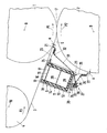
- the single figure shows a partial cross section through the nip area of a calender.
- a paper web 3 is pressure-treated between a hard roller 1 and a roller 2 provided with an elastic cover. It comes from a guide roller 4, runs over a steam humidifier 5, enters an inlet nip 6 and leaves the pair of rollers through an outlet nip 7.
- the rollers 1, 2 and 4 rotate in the direction of arrows P1, P2 and P3 about their respective axes 8, 9 and 10.
- the steam humidifier 5 has a hollow profile 11 which is formed by an outer U-shaped profile part 12, an inner U-profile part 14 provided with end flanges 13 and a closure plate 15 in which there are two rows of outlet openings 16 and 17.
- the cavity between the U-profile parts 12 and 14 is filled with thermal insulation 18.
- the fluid channel 19 can be divided into a plurality of channels by a partition 20 or a plurality of partitions, for example if different sections of the steam humidifier are to be supplied with steam at different temperatures or different pressures.
- the steam humidifier 5 can be pivoted as a whole about the axis 8 of the hard roller 1 in order to make the inlet gap 6 accessible.
- Each bar consists of several axially consecutive sections that can be individually adjusted so that their distance a from the roller surface is 8 mm or less, as required by the professional association.
- the strip 21 is fastened to a holder 24 via leaf springs 23, and the strip 22 is fastened to a holder 26 via leaf springs 25.
- the leaf springs bias the strips 21 and 22 towards the rollers 1 and 2, respectively.
- the adjustment device 27 has an adjustment element 30 which can be screwed into a holder 29 and to which a tension belt 31 is fastened. This is connected to the bar 21 after deflection on the hollow profile 11 and on a support rail 32.
- an adjusting element 34 which can be screwed into a holder 33 is connected to a tension belt 35 which, after deflection, engages on the bar 22 on a support rail 36.
- Several such adjustment devices 27 and 28 are provided over the length of the strips 21 and 22. If strips divided into individual sections are used, two such adjustment devices can be provided for each section. If a continuous, bendable strip is used, a number of adjustment devices corresponding to this design is necessary.
- the hollow profile 11 has a substantially rectangular cross section.
- the outlet openings 16 and 17 are located on one side wall.
- the brackets 29 and 33 for the adjusting elements 30 and 34 are located on the opposite side wall.
- the bracket 26 for the bar 22 is located on the opposite side wall.
- the bracket 24 for the bar 21 is attached on the side wall located therebetween. This shows that the bar 21, which is not accessible during operation, can experience the desired distance setting without difficulty because of the deflection of the tension belt 31 on the edge of the outer U-profile 12.
- the hollow profile can also have other cross sections, such as circular or square, if this corresponds to the design conditions.
- another device for heating, cooling or blowing the web or one of the rollers can also be combined with the strip protection device.
- the device is particularly suitable for the treatment of paper webs, but can also be used for other web materials such as textiles, foils and the like. be used.
Landscapes
- Engineering & Computer Science (AREA)
- General Engineering & Computer Science (AREA)
- Mechanical Engineering (AREA)
- Paper (AREA)
- Treatment Of Fiber Materials (AREA)
Applications Claiming Priority (2)
| Application Number | Priority Date | Filing Date | Title |
|---|---|---|---|
| DE3839056A DE3839056C2 (de) | 1988-11-18 | 1988-11-18 | Schutzvorrichtung für den Einlaufspalt von Kalandern und anderen Walzenmaschinen |
| DE3839056 | 1988-11-18 |
Publications (2)
| Publication Number | Publication Date |
|---|---|
| EP0369272A2 true EP0369272A2 (fr) | 1990-05-23 |
| EP0369272A3 EP0369272A3 (fr) | 1990-08-16 |
Family
ID=6367447
Family Applications (1)
| Application Number | Title | Priority Date | Filing Date |
|---|---|---|---|
| EP89120454A Withdrawn EP0369272A3 (fr) | 1988-11-18 | 1989-11-06 | Dispositif de protection pour la fente d'introduction de calandres ou autres machines de laminage |
Country Status (5)
| Country | Link |
|---|---|
| US (1) | US5042373A (fr) |
| EP (1) | EP0369272A3 (fr) |
| DE (1) | DE3839056C2 (fr) |
| FI (1) | FI90890C (fr) |
| NO (1) | NO894597L (fr) |
Families Citing this family (4)
| Publication number | Priority date | Publication date | Assignee | Title |
|---|---|---|---|---|
| DE29715644U1 (de) * | 1997-08-30 | 1997-10-23 | Gummiwerke Fulda GmbH, 36043 Fulda | Einrichtung zum Auseinanderfahren von Walzen eines Walzwerks, insbesondere Gummiwalzwerks |
| US6732452B2 (en) | 2001-12-21 | 2004-05-11 | Kimberly-Clark Worldwide, Inc. | Apparatus and process for throughair drying of a paper web |
| US6910283B1 (en) * | 2003-12-19 | 2005-06-28 | Kimberly-Clark Worldwide, Inc. | Method and system for heat recovery in a throughdrying tissue making process |
| US9187285B2 (en) * | 2012-11-19 | 2015-11-17 | Valmet Technologies, Inc. | Slitter-winder of a fiber production line |
Family Cites Families (15)
| Publication number | Priority date | Publication date | Assignee | Title |
|---|---|---|---|---|
| US3337968A (en) * | 1967-08-29 | Dryer section pocket ventilation | ||
| US629937A (en) * | 1898-09-09 | 1899-08-01 | Walter Knowles Trotman | Manufacture of paper. |
| GB525564A (en) * | 1939-02-22 | 1940-08-30 | Hovis Ltd | Improvements in or relating to guards for machines comprising rollers arranged in pairs |
| US2993432A (en) * | 1958-01-14 | 1961-07-25 | Beloit Iron Works | Calender air doctor |
| DE1157903B (de) * | 1959-09-24 | 1963-11-21 | Wilhelm Kumpf | Kalander, insbesondere Heisskalander, zum Erzeugen von Hochglanz auf gelacktem Papier |
| DE1228506B (de) * | 1962-11-29 | 1966-11-10 | Lodding Engineering Corp | Vorrichtung zum Aufbringen von Fluessigkeiten, insbesondere Wasser, auf Papier-bahnen in Papiermaschinen |
| US3242587A (en) * | 1964-12-07 | 1966-03-29 | Joseph H Dupasquier | Apparatus for concentrating a blanket of dry steam for an extended area on a pulp mat |
| DE1295993B (de) * | 1965-05-10 | 1969-05-22 | Kleinewefers Soehne J | Dampfbefeuchtungseinrichtung fuer Warenbahnen, insbesondere fuer Papierbahnen |
| DE1964194C3 (de) * | 1969-12-22 | 1973-11-08 | Westvaco Corp., New York, N.Y. (V.St.A.) | Vorrichtung zum Verteilen von Dampf auf eine laufende Bahn aus wasseraufnehmendem Material |
| US3994769A (en) * | 1972-04-14 | 1976-11-30 | Hermann Berstorff Maschinenbau Gmbh | Apparatus for continuously laminating a continuous strip of chipboard with decorative film |
| DE2914152C2 (de) * | 1979-04-07 | 1982-06-09 | M.A.N.- Roland Druckmaschinen AG, 6050 Offenbach | Sicherheitseinrichtung an Bogenrotationsdruckmaschinen zum Absichern eines Walzenspaltes, insbesondere zwischen Druck- und Gummizylinder |
| DD203869A1 (de) * | 1981-11-06 | 1983-11-09 | Hans Johne | Schutzvorrichtung an gegenlaeufigen zylindern von druckmaschinen |
| FI72552C (fi) * | 1984-02-08 | 1987-06-08 | Waertsilae Oy Ab | Foerfarande och anordning foer behandling av bana. |
| US4748906A (en) * | 1986-03-21 | 1988-06-07 | Accuray Corporation | Air shower apparatus and method |
| DE3719305C1 (de) * | 1987-06-10 | 1988-10-20 | Kleinewefers Gmbh | Schutzvorrichtung fuer den Einlaufspalt von Kalandern und anderen Walzenmaschinen |
-
1988
- 1988-11-18 DE DE3839056A patent/DE3839056C2/de not_active Expired - Fee Related
-
1989
- 1989-11-06 EP EP89120454A patent/EP0369272A3/fr not_active Withdrawn
- 1989-11-15 FI FI895444A patent/FI90890C/fi not_active IP Right Cessation
- 1989-11-17 NO NO89894597A patent/NO894597L/no unknown
- 1989-11-20 US US07/439,541 patent/US5042373A/en not_active Expired - Fee Related
Also Published As
| Publication number | Publication date |
|---|---|
| NO894597L (no) | 1990-05-21 |
| DE3839056C1 (fr) | 1990-01-18 |
| DE3839056C2 (de) | 1994-07-14 |
| US5042373A (en) | 1991-08-27 |
| NO894597D0 (no) | 1989-11-17 |
| FI90890C (fi) | 1994-04-11 |
| FI895444A0 (fi) | 1989-11-15 |
| EP0369272A3 (fr) | 1990-08-16 |
| FI90890B (fi) | 1993-12-31 |
Similar Documents
| Publication | Publication Date | Title |
|---|---|---|
| DE2925985C2 (de) | Vorrichtung zum berührungslosen Abstützen einer laufenden Bahn | |
| DE2837913C2 (de) | Walze mit steuerbarer Durchbiegung, insbesondere für Maschinen zur Erzeugung und Verarbeitung von Bahnen aus Papier oder Kunststoff | |
| DE69517193T2 (de) | Vorrichtung zum trocknen und glätten einer faserbahn | |
| DE3503448C2 (de) | Verfahren und Vorrichtung zum Befeuchten einer Endlosbahn | |
| DE3305429A1 (de) | Kalander zur druck- und waermebehandlung von warenbahnen | |
| EP0715019B1 (fr) | Procédé et dispositif pour traiter une bande de matériau | |
| DE3216182C2 (de) | Kalander für Papier- und andere Materialbahnen | |
| DE2243465B2 (de) | Kontinuierlich arbeitende presse | |
| EP0732445B2 (fr) | Calandre pour le traitement d'une bande de papier | |
| EP0967324B1 (fr) | Procédé pour le lissage d' une bande de papier | |
| EP1099019B2 (fr) | Dispositif d'encollage d'une portee de fils | |
| EP0708203A2 (fr) | Dispositif et méthode pour humidifier une bande de matériau en défilement | |
| DE102016101160B4 (de) | Vorrichtung zum schwebenden Führen und gleichzeitigem Abkühlen von bahnförmigem Material und Verfahren zum Betreiben einer solchen Vorrichtung | |
| DE3839056C1 (fr) | ||
| CH663234A5 (de) | Zweiwalzenkalander mit beheizten walzen. | |
| DE3336328A1 (de) | Hotflue | |
| AT399357B (de) | Kalander zum behandeln einer warenbahn, insbesondere einer papierbahn | |
| EP1854915B1 (fr) | Dispositif pour appliquer des agents fluides sur un matériau en bande | |
| CH670217A5 (fr) | ||
| EP0945385B1 (fr) | Triangle plieur d'un appareil de pliage d'une machine d'impression rotative | |
| EP0799933B1 (fr) | Calandre pour papier ou similaire | |
| EP0792965B1 (fr) | Procédé pour le satinage du papier et calandre pour l'application du procédé | |
| DE9102095U1 (de) | Kanalwand, insbesondere für einen Papiermaschinen-Stoffauflauf | |
| DE4402278C2 (de) | Vorrichtung zum Aufbringen von Dampf | |
| DE19534911C2 (de) | Kalander für die Behandlung einer Papierbahn |
Legal Events
| Date | Code | Title | Description |
|---|---|---|---|
| PUAI | Public reference made under article 153(3) epc to a published international application that has entered the european phase |
Free format text: ORIGINAL CODE: 0009012 |
|
| AK | Designated contracting states |
Kind code of ref document: A2 Designated state(s): BE FR IT NL SE |
|
| PUAL | Search report despatched |
Free format text: ORIGINAL CODE: 0009013 |
|
| AK | Designated contracting states |
Kind code of ref document: A3 Designated state(s): BE FR IT NL SE |
|
| 17P | Request for examination filed |
Effective date: 19900707 |
|
| 17Q | First examination report despatched |
Effective date: 19920305 |
|
| STAA | Information on the status of an ep patent application or granted ep patent |
Free format text: STATUS: THE APPLICATION IS DEEMED TO BE WITHDRAWN |
|
| 18D | Application deemed to be withdrawn |
Effective date: 19930123 |