EP0369300B1 - Mécanisme de direction assistée - Google Patents
Mécanisme de direction assistée Download PDFInfo
- Publication number
- EP0369300B1 EP0369300B1 EP89120620A EP89120620A EP0369300B1 EP 0369300 B1 EP0369300 B1 EP 0369300B1 EP 89120620 A EP89120620 A EP 89120620A EP 89120620 A EP89120620 A EP 89120620A EP 0369300 B1 EP0369300 B1 EP 0369300B1
- Authority
- EP
- European Patent Office
- Prior art keywords
- ribs
- rack
- guide
- guide groove
- groove
- Prior art date
- Legal status (The legal status is an assumption and is not a legal conclusion. Google has not performed a legal analysis and makes no representation as to the accuracy of the status listed.)
- Expired - Lifetime
Links
- 229920003002 synthetic resin Polymers 0.000 claims description 15
- 239000000057 synthetic resin Substances 0.000 claims description 15
- 239000012783 reinforcing fiber Substances 0.000 claims description 3
- 230000000052 comparative effect Effects 0.000 description 10
- 238000001746 injection moulding Methods 0.000 description 9
- 238000000034 method Methods 0.000 description 5
- 238000000465 moulding Methods 0.000 description 5
- 229920005989 resin Polymers 0.000 description 4
- 239000011347 resin Substances 0.000 description 4
- 238000010586 diagram Methods 0.000 description 3
- 230000003292 diminished effect Effects 0.000 description 3
- 239000000945 filler Substances 0.000 description 3
- 238000001816 cooling Methods 0.000 description 2
- 239000000956 alloy Substances 0.000 description 1
- 229910045601 alloy Inorganic materials 0.000 description 1
- 230000006835 compression Effects 0.000 description 1
- 238000007906 compression Methods 0.000 description 1
- 238000010276 construction Methods 0.000 description 1
- 230000008602 contraction Effects 0.000 description 1
- 230000003467 diminishing effect Effects 0.000 description 1
- 239000003365 glass fiber Substances 0.000 description 1
- 230000036316 preload Effects 0.000 description 1
- 230000008961 swelling Effects 0.000 description 1
Images


Classifications
-
- B—PERFORMING OPERATIONS; TRANSPORTING
- B62—LAND VEHICLES FOR TRAVELLING OTHERWISE THAN ON RAILS
- B62D—MOTOR VEHICLES; TRAILERS
- B62D3/00—Steering gears
- B62D3/02—Steering gears mechanical
- B62D3/12—Steering gears mechanical of rack-and-pinion type
- B62D3/123—Steering gears mechanical of rack-and-pinion type characterised by pressure yokes
-
- F—MECHANICAL ENGINEERING; LIGHTING; HEATING; WEAPONS; BLASTING
- F16—ENGINEERING ELEMENTS AND UNITS; GENERAL MEASURES FOR PRODUCING AND MAINTAINING EFFECTIVE FUNCTIONING OF MACHINES OR INSTALLATIONS; THERMAL INSULATION IN GENERAL
- F16H—GEARING
- F16H55/00—Elements with teeth or friction surfaces for conveying motion; Worms, pulleys or sheaves for gearing mechanisms
- F16H55/02—Toothed members; Worms
- F16H55/26—Racks
- F16H55/28—Special devices for taking up backlash
- F16H55/283—Special devices for taking up backlash using pressure yokes
-
- Y—GENERAL TAGGING OF NEW TECHNOLOGICAL DEVELOPMENTS; GENERAL TAGGING OF CROSS-SECTIONAL TECHNOLOGIES SPANNING OVER SEVERAL SECTIONS OF THE IPC; TECHNICAL SUBJECTS COVERED BY FORMER USPC CROSS-REFERENCE ART COLLECTIONS [XRACs] AND DIGESTS
- Y10—TECHNICAL SUBJECTS COVERED BY FORMER USPC
- Y10T—TECHNICAL SUBJECTS COVERED BY FORMER US CLASSIFICATION
- Y10T74/00—Machine element or mechanism
- Y10T74/19—Gearing
- Y10T74/19642—Directly cooperating gears
- Y10T74/1967—Rack and pinion
Definitions
- the present invention relates to a rack and pinion steering device according to the preamble of claim 1.
- Fig. 10 shows a rack and pinion steering device already known for use in motor vehicles.
- a pinion shaft 5 is rotatably supported by a housing 1 with bearings 2, 3 and an oil seal 4 provided therein around the shaft.
- a rack 8 formed on the rear side of a rack bar 7 extending through the housing 1 transversely thereof.
- the housing 1 is integral with a hollow cylindrical portion 9 projecting forward from the front side thereof.
- a cap 10 is screwed in the front end of the cylindrical portion 9 and fixed thereto with a lock nut 11.
- a rack guide 12 is fitted in between the cap 10 and the rack bar 7 in the cylindrical portion 9 so as to be slightly movable forward or rearward.
- the rack guide 12 is formed in its rear end with a guide groove 13 having the cylindrical front face of the rack bar 7 fitted therein to guide the bar 7.
- the guide groove 13 is defined by upper and lower rearward projections 14.
- the cap 10 and the rack guide 12 are formed in their opposed faces with circular spring accommodating cavities 15, 16, respectively, having a coiled compression spring 17 disposed therein.
- the rack guide 12 is pressed against the rack bar 7 by the spring 17 to guide the rack bar and preload the rack 8 relative to the pinion 6.
- a small clearance is provided between the cap 10 and the rack guide 12.
- the rack guide was prepared from sintered alloy or the like in the past, those made of synthetic resin have been placed into wide use in recent years since they permit smooth movement of the rack bar, and are lightweight, diminished in impact noise and inexpensive.
- the rack guide is prepared from synthetic resin, injection molding is generally resorted to.
- the rack guide will be satisfactory when made in the form of a block having no clearance, whereas the product then deforms greatly owing to the shrinkage involved in injection molding, hence a problem in respect of precision. Accordingly, the rack guide is prepared in the form of a hollow cylinder, but a problem then arises with respect to strength. More specifically stated with reference to Fig. 10, the rack guide 12 collides with the cap 10 secured to the housing cylindrical portion 9 when subjected to a force from the rack bar 7. At this time, the cylindrical portion only of the rack guide 12 is subjected to a force upon striking against the cap 10. The rack guide is therefore likely to break, failing to withstand the great force.
- the molding tends to shrink during cooling at the rear end portion where the guide groove 13 is formed, and becomes tapered toward the rear end. If the rear end portion shrinks uniformly in its entirety in this case without any directionality in the degree of shrinkage of this portion, it is possible to make the entire rack guide 12 uniform in outside diameter by dimensionally adjusting the molding die. However, it is impossible to give a uniform outside diameter to the entire rack guide 12 by adjusting the dimensions of the die since the degree of shrinkage is actually greater in the direction in which the projections 14 approach each other.
- the molding synthetic resin flows in the direction in which the guide groove 13 extends, with the result that the filler, such as glass fiber, used becomes oriented in the horizontal direction (i.e., the direction perpendicular to the plane of Fig. 10) in the portions forming the projections 14. Consequently, the filler fails to greatly reinforce the projections 14 by acting against the fall of these portions.
- the filler such as glass fiber
- the FR-A 2 546 468 discloses a rack and pinion steering device of the kind defined in the preamble of claim 1, having a rack guide made of synthetic resin and consisting of an inner and an outer cylindrical member being concentrically arranged with an annular space inbetween.
- the cylindrical portions are connected by two diametrically opposite ribs extending parallel to a guide groove of the rack guide receiving the rack bar of the steering device.
- the diameter of the rack guide in the plane including the ribs is smaller than the diameter in the direction perpendicular with respect to the plane of the ribs.
- the rack guide has an elliptic cross section.
- the main object of the present invention is to overcome the foregoing problems and provide a rack and pinion steering device having a rack guide made of synthetic resin which is excellent in both strength and precision.
- the steering device according to the invention is characterized by the characterizing features of claim 1.
- the corners of the ribs in the annular groove are rounded.
- the spring bearing portion in the spring accommodating cavity is provided with a rib parallel to the guide groove and a rib intersecting this rib at right angles therewith.
- the rack guide is in the form of a hollow double cylinder, the rack guide is made uniform in its overall wall thickness, diminished in deformation due to the shrinkage involved in injection molding and given improved precision. Further because the end face of the inner cylindrical portion is flush with or projects beyond the end face of the outer cylindrical portion, with the annular groove ribs parallel to the guide groove made flush with the end face of the inner cylindrical portion, at least the inner cylindrical portion and the ribs parallel to the guide groove collide with the cap or the like at the same time.
- the rack guide has increased strength and is resistant to damage or breaking because the plurality of ribs are provided between the inner and outer cylindrical portions and because at least the inner cylindrical portion and the ribs parallel to the guide groove are adapted to collide with the cap or the like at the same time.
- the ribs in the annular groove when rounded at their corners, impart further increased strength to the rack guide.
- the synthetic resin injected from a gate portion at the center of the guide groove of the rack guide to be formed by injection molding flows dividedly in four directions through the portion of the rib to be formed in parallel to the guide groove at the spring bearing portion in the rear of the gate and through the rib portion intersecting the rib portion. This diminishes the directionality of changes after the molding process.
- the filler used is oriented vertically in the projections and therefore acts against the shrinkage of the projections, reducing the tendency for the projections to fall and consequently diminishing the directionality of post-process changes of the synthetic resin rack guide made by injection molding to give higher dimensional accuracy to the rack guide.
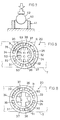
- FIG. 1 to 9 show rack guides for the steering device on an enlarged scale.
- Figs. 1 to 4 show one embodiment.
- the illustrated rack guide 20 is similar to the conventional one in contour and is formed at its rear end with a guide groove 21 and projections 22.
- the rear ends of the projections 22 are cut off so as to be parallel to the front end face of the guide and to form flat faces 23.
- the guide groove 21 has a circular-arc cross section in conformity with the cylindrical front face of the rack bar 7 and has in its bottom a clearance groove 24 extending longitudinally thereof.
- a shallow recess 25 is formed in the middle of the bottom of the clearance groove 24.
- An injection molding gate 26 is positioned at the bottom of the recess 25 centrally thereof.
- the guide groove 21 is further provided with oil grooves 27 perpendicular to the clearance groove 24 and extending from the groove 24 to the respective flat faces 23 of the projections 22.
- the projections 22 are chamfered as at 28 along their side edges. The portions surrounded by the flat faces 23 along the guide groove 21, the clearance groove 24, the oil grooves 27 and the chamfers 28 are slide guide faces 29 for guiding the rack bar
- the rack guide 20 is formed in its front end face with a circular spring accommodating cavity 30 centrally thereof and an annular groove 31 around the cavity 30 concentrically therewith.
- the rack guide 20 is in the form of a double cylinder having an inner cylindrical portion 32 and an outer cylindrical portion 33.
- the front end faces of the inner and outer cylindrical portions 32 and 33 are flush with each other.
- a plurality of ribs 34, 35, 36 and 37 are formed in the annular groove 31 between the inner and outer cylindrical portions 32 and 33 diametrically thereof.
- these ribs are two ribs 34 parallel to the guide groove 21, four slanting ribs 35 slightly slanting with respect to these ribs 34, two vertical ribs 36 perpendicular to the guide groove 21, that is, extending in a direction interconnecting the projections 22, and four inclined ribs 37 slightly inclined with respect to these ribs 36.
- the front faces of the groove-paralleling ribs 34 only are flush with the front end faces of the inner and outer cylindrical portions 32 and 33.
- the front faces of the other ribs 35, 36 and 37 are positioned slightly inside the annular groove 31, i.e., slightly rearward from the front end faces of the inner and outer cylindrical portions 32 and 33.
- the corners of the ribs, 34 to 37 are rounded as indicated at R.
- the inner cylindrical portion 32 is internally formed with a rib 38 in parallel to the guide groove 21 and having a relatively large width.
- Two ribs 39 extend from each side of the rib 38 to the inner periphery of the inner cylindrical portion 32 perpendicular to the rib 38.
- the front faces of these ribs 38 and 39 are flush with one another and are positioned a considerable distance rearwardly away from the front end face of the inner cylindrical portion 32. These front faces support one end of the spring 17.
- These ribs 38 and 39 are also rounded at their corners as indicated at R.
- the rack guide 20 is prepared by injection molding.
- the synthetic resin injected from the portion of gate 26 for injection molding flows dividedly in four directions through the portion of the groove-paralleling rib 38 and the portions of the ribs 39 perpendicular thereto which are inside the inner cylindrical portion 32 behind the gate 26.
- the synthetic resin is filled in the direction parallel to the guide groove 21, then filled in the directions perpendicular to the groove and further filled into the portions of the projections 22 in the direction parallel to the guide groove 21.
- the reinforcing fiber incorporated in the resin is of course oriented in the same direction as the flow of the resin. Consequently, the resin shrinks markedly in the direction in which the projections 22 approach each other during cooling, so that the post-process changes exhibit marked directionality.
- the synthetic resin is filled in the four directions at the same time, with the result that the reinforcing fiber is oriented in the portions of the projections 22 perpendicular to the guide groove 21. Accordingly, the directionality of the changes subsequent to the molding process is diminished. Further with the gate 26 positioned centrally of the rack guide, the resin can be filled smoothly, whereby the occurrence of weld marks and the like can be precluded.
- the rack guide 20 collides with the cap 10 (see Fig. 10) when subjected to a force by the rack bar 7, the guide exhibits high strength because the plurality of ribs 34 to 37 are formed between the inner and outer cylindrical portions 32 and 33 and are rounded as at R at their corners and further because the front faces of the inner and outer cylindrical portions 32, 33 and the groove-paralleling ribs 34 are flush with one another and strike against the cap 10 at the same time to withstand the force.
- Figs. 5 and 6 Six kinds of specimens (rack guides) were prepared as shown in Figs. 5 and 6.
- the hatched portion is positioned forward from the unhatched portion and is the portion to be brought into contact with the cap 10.
- the specimen has no groove-paralleling rib 34.
- the outer cylindrical portion 33 only is projected forward.
- the ribs 35, 36 and 37 are not rounded.
- the specimen has no groove-paralleling rib 34, and the inner and outer cylindrical portions 32, 33 are projected forward.
- the ribs 35, 36 and 37 are not rounded.
- No groove-paralleling rib 34 is formed, and the inner and outer cylindrical portions 32, 33 are projected forward.
- the ribs 35, 36 and 37 are rounded as at R.
- the specimen has groove-paralleling ribs 34, and the inner and outer cylindrical portions 32, 33 and projected forward.
- the ribs 34, 35, 36 and 37 are rounded as at R.
- the specimen has groove-paralleling ribs 34.
- the inner and outer cylindrical portions 32, 33 and the groove-paralleling ribs 34 are projected forward.
- the ribs 34, 35, 36 and 37 are rounded as at R.
- the specimen has groove-paralleling ribs 34.
- the inner and outer cylindrical portions 32, 33, the groove-paralleling ribs 34 and the vertical ribs 36 are projected forward.
- the ribs 34, 35, 36 and 37 are rounded as at R.
- Comparative Example 4 and Examples 1 and 2 indicate that the groove-paralleling ribs 34, and, when provided as projected forward, give improved strength to the rack guide.
- Example 2 The results achieved by Example 2 reveal that the positioning of the vertical ribs in the forwardly projected position leads to a slight improvement in strength.
- Fig. 8 shows another embodiment.
- the inner cylindrical portion 32 is internally provided with a groove-paralleling rib 50 and a perpendicular rib 51 which are arranged crosswise.
- the embodiment has the same construction as the first embodiment; like parts are designated by like reference numerals.
- Fig. 9 shows still another embodiment.
- the inner cylindrical portion 32 is internally formed with a plurality of groove-paralleling ribs 52 and a plurality of perpendicular ribs 53.
- the embodiment is the same as the first embodiment; like parts are designated by like reference numerals.
Landscapes
- Engineering & Computer Science (AREA)
- General Engineering & Computer Science (AREA)
- Mechanical Engineering (AREA)
- Chemical & Material Sciences (AREA)
- Combustion & Propulsion (AREA)
- Transportation (AREA)
- Transmission Devices (AREA)
- Moulds For Moulding Plastics Or The Like (AREA)
Claims (5)
- Mécanisme de direction à crémaillère dans lequel une cage (1) loge en son sein une glissière à crémaillère cylindrique creuse (12) faite de résine synthétique et pressée contre une barre à crémaillère (7) par un ressort (17) pour guider la barre à crémaillère et précharger la barre à crémaillère par rapport au pignon (6), la glissière à crémaillère (12) étant formée dans sa seule face terminale avec une rainure de guidage (13) pour guider la barre à crémaillère, la glissière à crémaillère (12) étant formée corne un cylindre double ayant une partie cylindrique intérieure (32), une partie cylindrique extérieure (33) et une rainure annulaire (31) entre elles, ladite partie cylindrique intérieure ayant une cavité de logement de ressort circulaire (30), des nervures (34) s'étendant entre les parties cylindriques intérieure et extérieure (32, 33) parallèles à ladite rainure de guidage (21), au moins lesdites rainures (34) s'étendant parallèlement à ladite rainure de guidage (21), ayant une face terminale opposée à ladite rainure de guidage (21) et étant de niveau avec les faces terminales desdites parties cylindriques intérieure et extérieure (32, 33), caractérisé par des nervures supplémentaires (35, 36, 37) s'étendant diamétralement entre lesdites parties cylindriques intérieure et extérieure, les nervures (35, 36, 37) étant espacées sur la circonférence.
- Mécanisme selon la revendication 1, caractérisé en ce que les coins (R) des nervures (34, 35, 36, 37) entre lesdites nervures et lesdites parties cylindriques (32, 33) sont arrondis.
- Mécanisme selon la revendication 1 ou 2, caractérisé en ce que la cavité de logement de ressort (30) contient une partie palier à ressort, un élément de nervure (38, 50, 52) étant parallèle à la rainure de guidage (21) et une nervure (39, 51, 53) coupant ledit élément de nervure à angle droit.
- Mécanisme selon l'une des revendications 1 à 3, caractérisé en ce qu'une entrée d'injection (26) pour résine synthétique est formée au centre d'une surface de ladite rainure de guidage (21).
- Mécanisme selon l'une des revendications 1 à 4, caractérisé en ce que les fibres de renfort sont remplies dans ladite résine synthétique.
Applications Claiming Priority (4)
| Application Number | Priority Date | Filing Date | Title |
|---|---|---|---|
| JP14581488U JPH0265676U (fr) | 1988-11-08 | 1988-11-08 | |
| JP145814/88 | 1988-11-08 | ||
| JP145812/88 | 1988-11-08 | ||
| JP1988145812U JPH0714106Y2 (ja) | 1988-11-08 | 1988-11-08 | ラックピニオン式ステアリング装置 |
Publications (3)
| Publication Number | Publication Date |
|---|---|
| EP0369300A2 EP0369300A2 (fr) | 1990-05-23 |
| EP0369300A3 EP0369300A3 (en) | 1990-09-05 |
| EP0369300B1 true EP0369300B1 (fr) | 1994-08-10 |
Family
ID=26476831
Family Applications (1)
| Application Number | Title | Priority Date | Filing Date |
|---|---|---|---|
| EP89120620A Expired - Lifetime EP0369300B1 (fr) | 1988-11-08 | 1989-11-07 | Mécanisme de direction assistée |
Country Status (3)
| Country | Link |
|---|---|
| US (1) | US5022279A (fr) |
| EP (1) | EP0369300B1 (fr) |
| DE (1) | DE68917426T2 (fr) |
Families Citing this family (11)
| Publication number | Priority date | Publication date | Assignee | Title |
|---|---|---|---|---|
| EP0860345A3 (fr) * | 1997-02-25 | 1998-11-11 | Trw Inc. | Guidage pour crémaillère |
| US5937703A (en) * | 1997-02-25 | 1999-08-17 | Trw Inc. | Rack guide |
| US6076417A (en) * | 1997-02-25 | 2000-06-20 | Trw Inc. | Rack guide having linear inner walls for supporting a rack |
| JP3676661B2 (ja) * | 2000-08-30 | 2005-07-27 | 光洋精工株式会社 | ラックピニオン式ステアリング装置 |
| US6591706B2 (en) | 2001-05-01 | 2003-07-15 | Trw Inc. | Rack and pinion steering gear with a unitized yoke assembly |
| ITBS20030011U1 (it) * | 2003-01-29 | 2004-07-30 | Trw Italia Spa | Pattino di scorrimento cremagliera per sistemi sterzanti |
| EP1462324A1 (fr) * | 2003-03-28 | 2004-09-29 | TRW Automotive GmbH | Entraínement pyrotechnique |
| EP1724180B1 (fr) * | 2004-03-09 | 2009-11-11 | Oiles Corporation | Guide de crémaillère et crémaillère et dispositif de levier de direction utilisant le guide de crémaillère |
| JP4631535B2 (ja) * | 2005-05-18 | 2011-02-16 | 株式会社ジェイテクト | ラックガイド及びこのラックガイドを具備したラックピニオン式ステアリング装置 |
| JP5126883B2 (ja) * | 2007-11-30 | 2013-01-23 | 大同メタル工業株式会社 | ラックピニオン式ステアリング装置の摺動受板及びラックガイド |
| JP2015202787A (ja) * | 2014-04-14 | 2015-11-16 | オイレス工業株式会社 | ラックガイド及びこのラックガイドを具備したラックピニオン式ステアリング装置 |
Family Cites Families (5)
| Publication number | Priority date | Publication date | Assignee | Title |
|---|---|---|---|---|
| GB1593398A (en) * | 1976-10-29 | 1981-07-15 | Cam Gears Ltd | Rack and pinion assemblies |
| DE2928732C2 (de) * | 1979-07-17 | 1982-10-21 | Zahnradfabrik Friedrichshafen Ag, 7990 Friedrichshafen | Zahnstangenlenkgetriebe, insbesondere für Kraftfahrzeuge |
| JPS5945149U (ja) * | 1982-09-17 | 1984-03-26 | トヨタ自動車株式会社 | ツクアンドピニオン式ステアリングギヤ装置 |
| JPS59216764A (ja) * | 1983-05-24 | 1984-12-06 | Toyota Motor Corp | ラックアンドピニオン式ステアリング装置 |
| US4785685A (en) * | 1986-04-09 | 1988-11-22 | Toyota Jidosha Kabushiki Kaisha | Rack guide of synthetic resin for a rack and pinion type steering device |
-
1989
- 1989-11-02 US US07/430,464 patent/US5022279A/en not_active Expired - Lifetime
- 1989-11-07 DE DE68917426T patent/DE68917426T2/de not_active Expired - Fee Related
- 1989-11-07 EP EP89120620A patent/EP0369300B1/fr not_active Expired - Lifetime
Also Published As
| Publication number | Publication date |
|---|---|
| EP0369300A3 (en) | 1990-09-05 |
| DE68917426D1 (de) | 1994-09-15 |
| US5022279A (en) | 1991-06-11 |
| EP0369300A2 (fr) | 1990-05-23 |
| DE68917426T2 (de) | 1995-03-30 |
Similar Documents
| Publication | Publication Date | Title |
|---|---|---|
| EP0369300B1 (fr) | Mécanisme de direction assistée | |
| EP0225003B1 (fr) | Vis à rainure à autoblocage | |
| US3627406A (en) | Spectacle frame with flexible sidebars | |
| JP3325679B2 (ja) | ボールねじのボール溝形状 | |
| GB2114718A (en) | Telescopic tube assembly suitable for an adjustable-height motor vehicle steering column | |
| EP2049866B1 (fr) | Fixation par moulage par injection pour des palpeurs | |
| US4683769A (en) | Rack guide in rack-and-pinion type steering gear | |
| KR20010014092A (ko) | 래크 제작 방법 | |
| EP0490541A1 (fr) | Support pour élément actif avec prévention des rayures | |
| EP0550185A1 (fr) | Article moulée sans déformation | |
| US4303221A (en) | Core pin for making a plastic connector shell having an internal keyway | |
| US6361309B1 (en) | Injection molding tool for producing a rolling bearing cage for a linear bearing | |
| JP2004108454A (ja) | ボールねじ用チューブガイド及びボールねじ並びにボールねじの製造方法 | |
| GB1591589A (en) | Spacer | |
| US4391473A (en) | Linear bearing unit | |
| JP3152601B2 (ja) | ディスク射出成形金型の固定側と可動側の円盤キャビティプレートの整列案内装置 | |
| JP3430208B2 (ja) | プラスチック光学レンズ用射出成形金型ならびにプラスチック光学レンズの製造方法 | |
| CN223394287U (zh) | 一种具有多级抽芯结构的压铸模具 | |
| CN114179305B (zh) | 一种滚刀柄的行位内抽斜针模具 | |
| KR100541327B1 (ko) | 판재의 프레스 성형 장치 | |
| US4869105A (en) | Instrument casing assembly | |
| US12459164B2 (en) | Method of manufacturing a mold body | |
| CN112622193B (zh) | 射出成型模具 | |
| KR102337561B1 (ko) | 사출성형기 | |
| JP3515097B2 (ja) | 自動車用ドアミラーステー |
Legal Events
| Date | Code | Title | Description |
|---|---|---|---|
| PUAI | Public reference made under article 153(3) epc to a published international application that has entered the european phase |
Free format text: ORIGINAL CODE: 0009012 |
|
| AK | Designated contracting states |
Kind code of ref document: A2 Designated state(s): DE FR GB |
|
| PUAL | Search report despatched |
Free format text: ORIGINAL CODE: 0009013 |
|
| AK | Designated contracting states |
Kind code of ref document: A3 Designated state(s): DE FR GB |
|
| 17P | Request for examination filed |
Effective date: 19910221 |
|
| 17Q | First examination report despatched |
Effective date: 19920504 |
|
| GRAA | (expected) grant |
Free format text: ORIGINAL CODE: 0009210 |
|
| AK | Designated contracting states |
Kind code of ref document: B1 Designated state(s): DE FR GB |
|
| REF | Corresponds to: |
Ref document number: 68917426 Country of ref document: DE Date of ref document: 19940915 |
|
| ET | Fr: translation filed | ||
| PLBE | No opposition filed within time limit |
Free format text: ORIGINAL CODE: 0009261 |
|
| STAA | Information on the status of an ep patent application or granted ep patent |
Free format text: STATUS: NO OPPOSITION FILED WITHIN TIME LIMIT |
|
| 26N | No opposition filed | ||
| REG | Reference to a national code |
Ref country code: GB Ref legal event code: IF02 |
|
| PGFP | Annual fee paid to national office [announced via postgrant information from national office to epo] |
Ref country code: GB Payment date: 20061101 Year of fee payment: 18 |
|
| PGFP | Annual fee paid to national office [announced via postgrant information from national office to epo] |
Ref country code: DE Payment date: 20061102 Year of fee payment: 18 |
|
| PGFP | Annual fee paid to national office [announced via postgrant information from national office to epo] |
Ref country code: FR Payment date: 20061108 Year of fee payment: 18 |
|
| GBPC | Gb: european patent ceased through non-payment of renewal fee |
Effective date: 20071107 |
|
| PG25 | Lapsed in a contracting state [announced via postgrant information from national office to epo] |
Ref country code: DE Free format text: LAPSE BECAUSE OF NON-PAYMENT OF DUE FEES Effective date: 20080603 |
|
| REG | Reference to a national code |
Ref country code: FR Ref legal event code: ST Effective date: 20080930 |
|
| PG25 | Lapsed in a contracting state [announced via postgrant information from national office to epo] |
Ref country code: GB Free format text: LAPSE BECAUSE OF NON-PAYMENT OF DUE FEES Effective date: 20071107 |
|
| PG25 | Lapsed in a contracting state [announced via postgrant information from national office to epo] |
Ref country code: FR Free format text: LAPSE BECAUSE OF NON-PAYMENT OF DUE FEES Effective date: 20071130 |