EP0369321B1 - Ventilateur à air circulé pour fours - Google Patents
Ventilateur à air circulé pour fours Download PDFInfo
- Publication number
- EP0369321B1 EP0369321B1 EP89120760A EP89120760A EP0369321B1 EP 0369321 B1 EP0369321 B1 EP 0369321B1 EP 89120760 A EP89120760 A EP 89120760A EP 89120760 A EP89120760 A EP 89120760A EP 0369321 B1 EP0369321 B1 EP 0369321B1
- Authority
- EP
- European Patent Office
- Prior art keywords
- drive shaft
- microwave oven
- muffle
- baking muffle
- spring element
- Prior art date
- Legal status (The legal status is an assumption and is not a legal conclusion. Google has not performed a legal analysis and makes no representation as to the accuracy of the status listed.)
- Expired - Lifetime
Links
- 239000011248 coating agent Substances 0.000 claims description 2
- 238000000576 coating method Methods 0.000 claims description 2
- 239000000463 material Substances 0.000 claims description 2
- 230000002500 effect on skin Effects 0.000 description 3
- 239000011521 glass Substances 0.000 description 3
- 230000005855 radiation Effects 0.000 description 3
- 230000000694 effects Effects 0.000 description 2
- 238000004519 manufacturing process Methods 0.000 description 2
- 238000004904 shortening Methods 0.000 description 2
- OKTJSMMVPCPJKN-UHFFFAOYSA-N Carbon Chemical compound [C] OKTJSMMVPCPJKN-UHFFFAOYSA-N 0.000 description 1
- 229910010293 ceramic material Inorganic materials 0.000 description 1
- 238000013016 damping Methods 0.000 description 1
- 229910002804 graphite Inorganic materials 0.000 description 1
- 239000010439 graphite Substances 0.000 description 1
- 239000002184 metal Substances 0.000 description 1
Images
Classifications
-
- H—ELECTRICITY
- H05—ELECTRIC TECHNIQUES NOT OTHERWISE PROVIDED FOR
- H05B—ELECTRIC HEATING; ELECTRIC LIGHT SOURCES NOT OTHERWISE PROVIDED FOR; CIRCUIT ARRANGEMENTS FOR ELECTRIC LIGHT SOURCES, IN GENERAL
- H05B6/00—Heating by electric, magnetic or electromagnetic fields
- H05B6/64—Heating using microwaves
- H05B6/647—Aspects related to microwave heating combined with other heating techniques
- H05B6/6473—Aspects related to microwave heating combined with other heating techniques combined with convection heating
-
- F—MECHANICAL ENGINEERING; LIGHTING; HEATING; WEAPONS; BLASTING
- F24—HEATING; RANGES; VENTILATING
- F24C—DOMESTIC STOVES OR RANGES ; DETAILS OF DOMESTIC STOVES OR RANGES, OF GENERAL APPLICATION
- F24C15/00—Details
- F24C15/32—Arrangements of ducts for hot gases, e.g. in or around baking ovens
- F24C15/322—Arrangements of ducts for hot gases, e.g. in or around baking ovens with forced circulation
-
- H—ELECTRICITY
- H05—ELECTRIC TECHNIQUES NOT OTHERWISE PROVIDED FOR
- H05B—ELECTRIC HEATING; ELECTRIC LIGHT SOURCES NOT OTHERWISE PROVIDED FOR; CIRCUIT ARRANGEMENTS FOR ELECTRIC LIGHT SOURCES, IN GENERAL
- H05B6/00—Heating by electric, magnetic or electromagnetic fields
- H05B6/64—Heating using microwaves
- H05B6/76—Prevention of microwave leakage, e.g. door sealings
Definitions
- the invention relates to a microwave oven with a circulating air fan for circulating air in the baking muffle, in which an electric motor is fastened to the baking muffle rear wall by means of a bearing bracket and the drive shaft of the electric motor projects through an opening into the baking muffle.
- the passage opening for the drive shaft in the back wall of the baking muffle is particularly critical, but also the drive shaft itself. In order to achieve a certain exit damping, the opening should not exceed a quarter of the wavelength of the high frequency. This condition can be met without major difficulties. It is much more difficult to get a grip on the part of the high frequency that comes out through the drive shaft.
- the drive shaft acts as a radiator (part an antenna), whereby the baking muffle wall is used as an electrical counterweight.
- the shortening factor is a function of the material and the diameter of the drive shaft. Part of the energy radiated by the drive shaft is damped by the stator package of the drive motor and the bearing brackets and converted into heat, but the free part can radiate unhindered.
- a microwave oven is also known (DE-A-31 04 627) in which the muffle is designed to be microwave-proof.
- a microwave throttle is arranged at the opening through which the drive shaft of the blower motor projects into the muffle, both inside and outside the muffle.
- Each microwave choke consists of a cavity resonator, which are coupled to one another via the opening in the muffle rear wall and the drive shaft of the blower motor.
- the microwave chokes create a high impedance in the area of the opening, as a result of which the microwave energy which wants to escape from the muffle is largely reflected.
- the object of the invention is therefore to find an effective and inexpensive solution to prevent the radiation of high-frequency energy via the drive shaft.
- the solution according to the invention consists in that a short circuit for high-frequency currents is arranged outside the baking muffle rear wall and the drive shaft.
- the advantage of the invention is that a metal drive shaft is still used.
- use is made of the fact that the skin effect is pronounced due to the high frequencies (of the order of about 2.5 GHz). This means that the electrical energy comes out of the baking muffle mainly via the surface of the drive shaft.
- the high-frequency energy reaching the surface on the outside is picked up near the shaft by an electrically conductive element, for example a pair of clamping glasses, and short-circuited via the rear wall of the baking muffle.
- an electrically conductive element for example a pair of clamping glasses
- This not only ensures the shortest possible electrical path, but also ensures that tolerances due to production or operation (thermal expansion) are compensated for.
- a further advantage of the invention results when the piece of the drive shaft protruding from the baking muffle is roughened and / or provided with an electrically poorly conductive layer. Due to the already mentioned skin effect, less high-frequency energy escapes through a roughened surface than through a smooth (dead-run effect!).
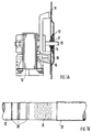
- Fig. 1a 10 denotes a drive motor which is flanged via a three-armed bearing bracket 16 to the rear wall 11 of the baking muffle of a baking oven, which is only partially shown.
- a drive shaft denoted by 12 projects through an opening 17 into the interior of the baking muffle and drives a fan wheel (not shown) there.
- a conductive connection designated 13 Between baking muffle rear wall 11 and drive shaft 12 there is a conductive connection designated 13, in the exemplary embodiment described here, a pair of clamping glasses.
- the clamping glasses 13 are attached to a socket 14.
- a shielding plate 15 is also provided.
- the arrangement shown works as follows: If high-frequency energy reaches the outside through the opening 17 from the interior of the baking muffle via the drive shaft 12, it is short-circuited via the conductive connection 13, in this case by means of a pair of clamps, via the back wall of the baking muffle. Since the energy transport of high-frequency energy from the interior of the baking muffle to the outside takes place essentially on the surface of the drive shaft due to the skin effect, this measure prevents high-frequency energy from reaching the bearing bracket or the motor.
- the socket 14 is held by the shielding plate 15.
- the purpose of the shield plate 15 is a further high-frequency shield.
- the spring element 13 is attached to the socket 14.
- the conductive connection 13 is connected to the three-armed bracket 16, so the socket is missing. It is essential that the high-frequency energy reaching the outside is short-circuited via the back wall of the baking muffle so that electrical energy cannot be emitted.
- the use of a spring element as a conductive connection also compensates for manufacturing and operational tolerances.
- One way to minimize the amount of high-frequency energy that escapes to the outside is to roughen the part of the drive shaft that lies outside the baking muffle and / or with an electrically poorly conductive layer (reference numeral 32, FIG. 1b) cover. These measures dampen both the transport of the RF energy from the rear wall (reduction in conductivity) and the radiation of the wave outside the baking muffle (dead-running effect).
- 1b shows a drive shaft which is provided with knurling 31 and a plurality of grooves 30.
- a graphite layer is suitable as a coating.
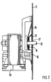
- Fig. 2 shows a second embodiment of the invention.
- the same reference numerals designate the same elements as in FIG. 1.
- the bushing 14 carrying the spring element is here connected directly to the bearing bracket 16.
- the difference between the two exemplary embodiments results from the different design of the baking muffle rear wall.
Landscapes
- Physics & Mathematics (AREA)
- Electromagnetism (AREA)
- Engineering & Computer Science (AREA)
- Chemical & Material Sciences (AREA)
- Combustion & Propulsion (AREA)
- Mechanical Engineering (AREA)
- General Engineering & Computer Science (AREA)
- Structures Of Non-Positive Displacement Pumps (AREA)
- Constitution Of High-Frequency Heating (AREA)
- Electric Ovens (AREA)
Claims (9)
- Four à micro-ondes comportant un ventilateur de circulation de l'air pour recycler l'air dans le moufle du four, dans le cas duquel un moteur électrique (10) est fixé à la paroi arrière (11) du moufle du four au moyen d'un étrier porte-palier (16) et l'arbre d'entraînement (12) du moteur électrique (10) pénètre dans le moufle du four par une ouverture (17),
caractérisé par le fait qu'à l'extérieur du moufle du four, entre la paroi arrière (11) du moufle du four et l'arbre d'entraînement (12) est disposé un court-circuit pour courants de haute fréquence. - Four à micro-ondes selon la revendication 1,
caractérisé par le fait que le court-circuit est constitué d'un élément formant ressort (13). - Four à micro-ondes selon la revendication 2,
caractérisé par une rondelle Belleville ou une monture de bridage comme élément formant ressort. - Four à micro- ondes selon la revendication 2,
caractérisé par une tôle de blindage (15) reliée, avec conduction, avec la paroi arrière (11) du moufle du four et l'élément formant ressort (13). - Four à micro-ondes selon la revendication 2,
caractérisé par un coussinet (14) pouvant coulisser librement sur l'arbre d'entraînement selon le sens axial et relié, avec conduction électrique, avec l'élément formant ressort (13). - Four à micro-ondes selon la revendication 2,
caractérisé par le fait que l'élément formant ressort (13) est fixé à l'étrier porte-palier (16). - Four à micro-ondes selon la revendication 1,
caractérisé par le fait que la partie de l'arbre d'entraînement (12) qui se trouve à l'extérieur du moufle du four (11) est rendue fortement rugueuse. - Four à micro-ondes selon la revendication 7,
caractérisé par le fait que la surface de l'arbre d'entraînement (12) est munie d'un moletage (31) et/ou de rainures obtenues au tour par saignée. - Four à micro-ondes selon la revendication 8,
caractérisé par le fait que la surface de l'arbre d'entraînement (12) est revêtue d'une couche (32) d'un matériau à grande résistance électrique.
Applications Claiming Priority (2)
| Application Number | Priority Date | Filing Date | Title |
|---|---|---|---|
| DE3838447A DE3838447A1 (de) | 1988-11-12 | 1988-11-12 | Umluftgeblaese fuer backoefen |
| DE3838447 | 1988-11-12 |
Publications (3)
| Publication Number | Publication Date |
|---|---|
| EP0369321A2 EP0369321A2 (fr) | 1990-05-23 |
| EP0369321A3 EP0369321A3 (en) | 1990-12-27 |
| EP0369321B1 true EP0369321B1 (fr) | 1995-03-01 |
Family
ID=6367073
Family Applications (1)
| Application Number | Title | Priority Date | Filing Date |
|---|---|---|---|
| EP89120760A Expired - Lifetime EP0369321B1 (fr) | 1988-11-12 | 1989-11-09 | Ventilateur à air circulé pour fours |
Country Status (3)
| Country | Link |
|---|---|
| US (1) | US4973825A (fr) |
| EP (1) | EP0369321B1 (fr) |
| DE (2) | DE3838447A1 (fr) |
Families Citing this family (1)
| Publication number | Priority date | Publication date | Assignee | Title |
|---|---|---|---|---|
| JP3437443B2 (ja) * | 1997-08-08 | 2003-08-18 | シャープ株式会社 | 高周波加熱装置 |
Family Cites Families (12)
| Publication number | Priority date | Publication date | Assignee | Title |
|---|---|---|---|---|
| US4053730A (en) * | 1976-05-17 | 1977-10-11 | Litton Systems Inc. | Microwave oven shaft seal |
| US4211909A (en) * | 1978-05-15 | 1980-07-08 | Sanyo Electric Co., Ltd. | Combination microwave and gas oven |
| US4358653A (en) * | 1977-11-25 | 1982-11-09 | Raytheon Company | Combination microwave oven |
| US4335290A (en) * | 1978-01-05 | 1982-06-15 | Raytheon Company | Microwave oven blower radiator |
| EP0006997B1 (fr) * | 1978-07-12 | 1983-01-19 | Bosch-Siemens HausgerÀ¤te GmbH | Four à micro-ondes |
| US4308417A (en) * | 1979-06-19 | 1981-12-29 | International Computers Limited | Electrical sealing device |
| DE3104627A1 (de) * | 1980-07-23 | 1982-11-11 | Licentia Patent-Verwaltungs-Gmbh, 6000 Frankfurt | Mikrowellenheizgeraet |
| DE3028352C2 (de) * | 1980-07-25 | 1982-10-14 | Bosch-Siemens Hausgeräte GmbH, 7000 Stuttgart | Mikrowellenofen |
| US4485285A (en) * | 1983-03-07 | 1984-11-27 | Control Data Corporation | Quarterwave choke for a microwave oven quartz lamp |
| US4687908A (en) * | 1985-12-23 | 1987-08-18 | Parallel Industries, Inc. | Convection blower for conventional electric ovens |
| US4764651A (en) * | 1987-09-23 | 1988-08-16 | Whirlpool Corporation | Grounding of stirrer bushing in a microwave oven |
| DE3810684A1 (de) * | 1988-03-29 | 1989-10-19 | Bosch Siemens Hausgeraete | Geblaese fuer einen umluftherd |
-
1988
- 1988-11-12 DE DE3838447A patent/DE3838447A1/de not_active Withdrawn
-
1989
- 1989-06-19 US US07/367,634 patent/US4973825A/en not_active Expired - Lifetime
- 1989-11-09 EP EP89120760A patent/EP0369321B1/fr not_active Expired - Lifetime
- 1989-11-09 DE DE58909058T patent/DE58909058D1/de not_active Expired - Fee Related
Also Published As
| Publication number | Publication date |
|---|---|
| US4973825A (en) | 1990-11-27 |
| DE3838447A1 (de) | 1990-05-17 |
| DE58909058D1 (de) | 1995-04-06 |
| EP0369321A2 (fr) | 1990-05-23 |
| EP0369321A3 (en) | 1990-12-27 |
Similar Documents
| Publication | Publication Date | Title |
|---|---|---|
| DE2058419A1 (de) | Verlustbehaftetes Hochfrequenzfilter | |
| DE827660C (de) | Verstaerker fuer kurze elektromagnetische Wellen | |
| DE2333221A1 (de) | Magnetron | |
| DE2410962C3 (de) | Bestrahlungsvorrichtung mit einem Magnetron als Oszillator | |
| DE2516335A1 (de) | Mikrowellenroehre | |
| DE970616C (de) | Verzoegerungsleitung der Bauart mit ineinandergreifenden Stegen fuer Elektronenstrahlroehren | |
| DE1099093B (de) | Anordnung zum Ankoppeln der wendelfoermigen Verzoegerungsleitung einer Wanderfeldroehre an einen Hohlleiter | |
| DE2844128C2 (de) | Mikrowellenofen | |
| DE7830898U1 (de) | Mikrowellenofen | |
| EP0369321B1 (fr) | Ventilateur à air circulé pour fours | |
| DE2733660C2 (de) | Wanderfeld-Verstärkerröhre | |
| DE2848658A1 (de) | Mikrowellenherd oder -ofen | |
| DE3134588A1 (de) | Wanderfeldroehre | |
| DE2125100C3 (de) | Megnetron | |
| DE3044379C2 (fr) | ||
| DE69401630T2 (de) | Kondensator für das Magnetron eines Mikrowellenofens | |
| DE3211971C2 (fr) | ||
| DE2433945A1 (de) | Magnetronvorrichtung | |
| DE2528396C3 (de) | Hochfrequenzelektronenröhre | |
| DE2535047C2 (de) | Stabförmige Sende- und Empfangsantenne in Form eines über einem Gegengewicht angebrachten mittengespeisten Dipols | |
| DE3736556A1 (de) | Schutzvorrichtung fuer die drehtellerwelle eines mikrowellenherds | |
| DE7833977U1 (de) | Herd oder ofen fuer verbundbetrieb mit mikrowellenenergie und widerstandsheizung | |
| DE69212775T2 (de) | Magnetron für einen Mikrowellenherd | |
| DE1615504A1 (de) | Mikrowellen-Heizeinrichtung | |
| DE19757360A1 (de) | Mikrowellenofen |
Legal Events
| Date | Code | Title | Description |
|---|---|---|---|
| PUAI | Public reference made under article 153(3) epc to a published international application that has entered the european phase |
Free format text: ORIGINAL CODE: 0009012 |
|
| AK | Designated contracting states |
Kind code of ref document: A2 Designated state(s): DE FR GB IT |
|
| PUAL | Search report despatched |
Free format text: ORIGINAL CODE: 0009013 |
|
| RHK1 | Main classification (correction) |
Ipc: F24C 15/32 |
|
| AK | Designated contracting states |
Kind code of ref document: A3 Designated state(s): DE FR GB IT |
|
| 17P | Request for examination filed |
Effective date: 19910622 |
|
| 17Q | First examination report despatched |
Effective date: 19910925 |
|
| RAP3 | Party data changed (applicant data changed or rights of an application transferred) |
Owner name: ALCATEL SEL AKTIENGESELLSCHAFT |
|
| GRAA | (expected) grant |
Free format text: ORIGINAL CODE: 0009210 |
|
| AK | Designated contracting states |
Kind code of ref document: B1 Designated state(s): DE FR GB IT |
|
| REF | Corresponds to: |
Ref document number: 58909058 Country of ref document: DE Date of ref document: 19950406 |
|
| GBT | Gb: translation of ep patent filed (gb section 77(6)(a)/1977) |
Effective date: 19950314 |
|
| ITF | It: translation for a ep patent filed | ||
| ET | Fr: translation filed | ||
| PLBE | No opposition filed within time limit |
Free format text: ORIGINAL CODE: 0009261 |
|
| STAA | Information on the status of an ep patent application or granted ep patent |
Free format text: STATUS: NO OPPOSITION FILED WITHIN TIME LIMIT |
|
| 26N | No opposition filed | ||
| REG | Reference to a national code |
Ref country code: GB Ref legal event code: 732E |
|
| PGFP | Annual fee paid to national office [announced via postgrant information from national office to epo] |
Ref country code: GB Payment date: 20001024 Year of fee payment: 12 |
|
| PGFP | Annual fee paid to national office [announced via postgrant information from national office to epo] |
Ref country code: DE Payment date: 20001221 Year of fee payment: 12 |
|
| PG25 | Lapsed in a contracting state [announced via postgrant information from national office to epo] |
Ref country code: GB Free format text: LAPSE BECAUSE OF NON-PAYMENT OF DUE FEES Effective date: 20011109 |
|
| REG | Reference to a national code |
Ref country code: GB Ref legal event code: IF02 |
|
| GBPC | Gb: european patent ceased through non-payment of renewal fee |
Effective date: 20011109 |
|
| PG25 | Lapsed in a contracting state [announced via postgrant information from national office to epo] |
Ref country code: DE Free format text: LAPSE BECAUSE OF NON-PAYMENT OF DUE FEES Effective date: 20020702 |
|
| PGFP | Annual fee paid to national office [announced via postgrant information from national office to epo] |
Ref country code: FR Payment date: 20041112 Year of fee payment: 16 |
|
| PG25 | Lapsed in a contracting state [announced via postgrant information from national office to epo] |
Ref country code: IT Free format text: LAPSE BECAUSE OF NON-PAYMENT OF DUE FEES;WARNING: LAPSES OF ITALIAN PATENTS WITH EFFECTIVE DATE BEFORE 2007 MAY HAVE OCCURRED AT ANY TIME BEFORE 2007. THE CORRECT EFFECTIVE DATE MAY BE DIFFERENT FROM THE ONE RECORDED. Effective date: 20051109 |
|
| PG25 | Lapsed in a contracting state [announced via postgrant information from national office to epo] |
Ref country code: FR Free format text: LAPSE BECAUSE OF NON-PAYMENT OF DUE FEES Effective date: 20060731 |
|
| REG | Reference to a national code |
Ref country code: FR Ref legal event code: ST Effective date: 20060731 |