EP0369414A1 - Appareil d'anesthésie dentaire - Google Patents
Appareil d'anesthésie dentaire Download PDFInfo
- Publication number
- EP0369414A1 EP0369414A1 EP89121096A EP89121096A EP0369414A1 EP 0369414 A1 EP0369414 A1 EP 0369414A1 EP 89121096 A EP89121096 A EP 89121096A EP 89121096 A EP89121096 A EP 89121096A EP 0369414 A1 EP0369414 A1 EP 0369414A1
- Authority
- EP
- European Patent Office
- Prior art keywords
- output signal
- intensity
- patient
- conductive element
- electrode
- Prior art date
- Legal status (The legal status is an assumption and is not a legal conclusion. Google has not performed a legal analysis and makes no representation as to the accuracy of the status listed.)
- Withdrawn
Links
- 206010002091 Anaesthesia Diseases 0.000 title claims abstract description 18
- 230000037005 anaesthesia Effects 0.000 title claims abstract description 18
- 239000000853 adhesive Substances 0.000 claims abstract description 19
- 230000001070 adhesive effect Effects 0.000 claims abstract description 19
- 229920001971 elastomer Polymers 0.000 claims abstract description 11
- 239000000806 elastomer Substances 0.000 claims abstract description 11
- 230000004936 stimulating effect Effects 0.000 claims abstract description 8
- 230000000638 stimulation Effects 0.000 claims abstract description 6
- 210000005036 nerve Anatomy 0.000 claims abstract description 4
- 239000012790 adhesive layer Substances 0.000 claims description 8
- OKTJSMMVPCPJKN-UHFFFAOYSA-N Carbon Chemical group [C] OKTJSMMVPCPJKN-UHFFFAOYSA-N 0.000 claims description 3
- 229910052799 carbon Inorganic materials 0.000 claims description 3
- 239000006260 foam Substances 0.000 claims description 3
- 229920001296 polysiloxane Polymers 0.000 claims description 3
- 239000006261 foam material Substances 0.000 abstract description 4
- 239000003990 capacitor Substances 0.000 description 13
- 238000004804 winding Methods 0.000 description 9
- 238000010586 diagram Methods 0.000 description 8
- 239000004020 conductor Substances 0.000 description 3
- 230000009977 dual effect Effects 0.000 description 3
- 230000036407 pain Effects 0.000 description 3
- 230000003444 anaesthetic effect Effects 0.000 description 2
- 230000000694 effects Effects 0.000 description 2
- 238000002955 isolation Methods 0.000 description 2
- 239000004698 Polyethylene Substances 0.000 description 1
- 230000004397 blinking Effects 0.000 description 1
- 238000010276 construction Methods 0.000 description 1
- 239000007772 electrode material Substances 0.000 description 1
- 239000004615 ingredient Substances 0.000 description 1
- 238000009413 insulation Methods 0.000 description 1
- 239000004973 liquid crystal related substance Substances 0.000 description 1
- 239000003589 local anesthetic agent Substances 0.000 description 1
- -1 polyethylene Polymers 0.000 description 1
- 229920000573 polyethylene Polymers 0.000 description 1
Images




Classifications
-
- A—HUMAN NECESSITIES
- A61—MEDICAL OR VETERINARY SCIENCE; HYGIENE
- A61N—ELECTROTHERAPY; MAGNETOTHERAPY; RADIATION THERAPY; ULTRASOUND THERAPY
- A61N1/00—Electrotherapy; Circuits therefor
- A61N1/02—Details
- A61N1/025—Digital circuitry features of electrotherapy devices, e.g. memory, clocks, processors
-
- A—HUMAN NECESSITIES
- A61—MEDICAL OR VETERINARY SCIENCE; HYGIENE
- A61N—ELECTROTHERAPY; MAGNETOTHERAPY; RADIATION THERAPY; ULTRASOUND THERAPY
- A61N1/00—Electrotherapy; Circuits therefor
- A61N1/02—Details
- A61N1/04—Electrodes
- A61N1/05—Electrodes for implantation or insertion into the body, e.g. heart electrode
- A61N1/0526—Head electrodes
- A61N1/0548—Oral electrodes
-
- A—HUMAN NECESSITIES
- A61—MEDICAL OR VETERINARY SCIENCE; HYGIENE
- A61N—ELECTROTHERAPY; MAGNETOTHERAPY; RADIATION THERAPY; ULTRASOUND THERAPY
- A61N1/00—Electrotherapy; Circuits therefor
- A61N1/18—Applying electric currents by contact electrodes
- A61N1/32—Applying electric currents by contact electrodes alternating or intermittent currents
- A61N1/36—Applying electric currents by contact electrodes alternating or intermittent currents for stimulation
- A61N1/36014—External stimulators, e.g. with patch electrodes
- A61N1/36021—External stimulators, e.g. with patch electrodes for treatment of pain
Definitions
- This invention relates to dental anesthesia apparatus, and, more particularly, relates to an electronic device for applying electrical signals through electrodes positioned inside the mouth of a patient to effect dental anesthesia.
- anesthesia has commonly been accomplished by use of a local anesthetic injected through a needle inserted to, or adjacent to the gum of the patient.
- This invention provides an improved dental anesthesia apparatus that includes an electronic stimulator that is connected with electrodes to provide a stimulating signal inside the mouth of a patient to preclude the feeling of pain by the patient while dental work is being performed on the patient.
- the stimulation is in the form of a pulsed DC signal, an AC signal, or pulsed DC signal followed by an AC signal, with the pulsed DC signal, when utilized, being offset to a fixed quiescent level above a zero volt level to improve the anesthetic effect and with application of the pulsed DC signal followed by application of the AC signal being timewise controlled manually or automatically.
- a first intensity level control is positioned at the main unit of the apparatus for use by the operator, such as the dentist, for example, and a second intensity level control is positioned remote from the main unit for use by the patient so that, for example, the threshold intensity can be selected by the dentist and the patient can thereafter increase the intensity level above the dentist selected threshold level.
- Readily viewable digital and bar graph displays of the intensity level selected are also provided.
- Each electrode includes an insulating base, preferably of foam material, having an adhesive on one side thereof to retain one end of the associated electrical lead in contact with an electrical conductor, preferably an elastomer, which conductor has a surrounding adhesive layer capable of releasably maintaining the conductor positioned inside the mouth of the patient.
- the present invention also provides an improved dental anesthesia apparatus that includes an electrical stimulator for providing pulsed DC output signal, an AC output signal or a pulsed DC output signal followed by an AC output signal, with the pulsed DC output signal, when utilized, being offset to a fixed quiescent level above zero volts, and with the application of the pulsed DC output signal followed by application of the AC output signal being timewise controlled.
- the present invention also provides an improved dental anesthesia apparatus that includes an electrode having an insulating base with an adhesive on one side thereof to maintain one end of an electrical lead in contact with an electrically conductive element, which element has a second adhesive capable of maintaining the element positioned inside the mouth of a patient.
- the apparatus 14 of this invention is shown in FIGURE 1 to include a main unit 16 having the electronic circuitry of the apparatus therein.
- a base 18 is preferably provided for positioning of unit 16 thereon, and base 18 also has a ledge 20 therein for receiving remote controller 22 when not being utilized by a patient remote from main unit 16.
- Remote controller 22 is connected to unit 16 by means of electrical lead 24, and remote controller 22 has an intensity level control actuator 26 thereon to normally allow a patient to remotely select a desired level of intensity.
- unit 16 has an off/on switch 28 at the front face thereof and intensity level control actuator 30 to be normally operated by an operator (such as a dentist or other user).
- a digital display 32 and a bar graph display 34 are also provided to indicate the intensity then selected.
- a plurality of jacks (or other conventional connectors) (not shown) are provided at the rear face of the unit, which jacks receive, for example, standard plugs which are electrically connected through leads 36a-d to a plurality of electrodes 38a-d.
- jacks receive, for example, standard plugs which are electrically connected through leads 36a-d to a plurality of electrodes 38a-d.
- electrodes are shown herein for use with a dual channel device, but it is to be appreciated that a single channel could be utilized requiring only two leads and two associated electrodes.
- Electrodes 38a-d may be identical and are configured in such a way as to be held in place inside the mouth of a patient (usually at the gum of the patient, as by being self-adhering to the gum, for example) to allow effective electronic dental anesthesia of the patient.
- Electrode 38a is illustrated as an example of electrode configuration (the remainder of the electrodes are preferably of like configuration although dimensions may be varied as needed) in FIGURES 2 and 3.
- electrode 38a includes an insulating base 42 (preferably of foam material, which foam material may be, for example, a polyethylene foam) having an adhesive 44 (such as, for example a medical grade adhesive) on the inner side thereof.
- the associated electrical lead, or wire, 36a has the normal insulation thereon removed at the free end 46 and the free end of the wire is positioned centrally on insulating base 42 and maintained in the selected position by adhesive 44.
- An electrically conductive element 48 (preferably an electrically conductive elastomer, which elastomer may be, for example, carbon impregnated silicone), having dimensions smaller than that of insulating base 42, is positioned over free end 46 of the wire and likewise is held in position by adhesive 44 on insulating base 42.
- Adhesive layer 50 (such as, for example, a hydrophilic FDA ingredient approved adhesive), having dimensions slightly larger than that of insulating base 42, has a central notch 52 therein, and adhesive layer 50 is maintained in the desired position by adhesive 44 on insulating base 42 so that adhesive layer 50 effectively surrounds elastomer 48 so that elastomer 48 extends through notch 52.
- the insulating base utilized was a medical foam known as DEV-7298
- the adhesive was MA-24
- the elastomer was carbon impregnated silicone
- the hydrophilic adhesive was known as Wetstick, with all of the foregoing being commonly available from Adhesives Research, Inc.
- the outer side of adhesive layer 50 (i.e., the side facing away from insulating base 42) must be capable of adhering to a wet surface such as commonly found inside the mouth of a patient so that adhesive layer 50 releasably maintains the elastomer in position in contact with the desired portion (for example, the gum) inside the mouth of the patient.
- the stimulating signal generated by the stimulating unit is coupled to the electrodes and directly applied to the desired portion inside the mouth of the patient to preclude the feeling of pain by the patient during dental or other work inside the mouth of the patient.
- the electrode materials, configurations and/or dimensions illustrated could be varied as needed for a particular application so long as the stimulating signal is directly delivered through an electrode in contact with a body portion within the mouth (such as the gum) with the electrode preferably being releasably maintained in position by an adhesive also contacting the body portion.
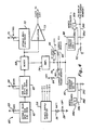
- the electronic circuitry of apparatus 14 is shown in block form in FIGURE 4. As shown, power for the unit is supplied by batteries 56 (which are also positioned inside unit 16), and application of power is controlled by off/on switch 28. With switch 28 in the on, or closed, position, the voltage from batteries 56 is coupled to power supply invertor 58 which supplies the necessary voltages to the various portions of the unit for operation.
- signal generating portion 60 of the device (which may be a transcutaneous nerve stimulator) includes rate generator 62, which generator is preferably an astable multivibrator, that provides an output signal, the rate of which is adjustable by potentiometer 63 between about 9 Hz and 40 Hz (for example adjustable between 0 and 50 K ⁇ ).
- the output signal from rate generator 62 is coupled to width generator 65, which generator is preferably a one-shot multivibrator, that provides an output signal the width of which is adjustable by potentiometer 66 between about 6 milliseconds and 45 milliseconds (for example adjustable between 0 and 50 K ⁇ ).
- the output signal from width generator 65 is coupled as one input to mixer 68 (for example a Z4L14), which mixer receives a second input from high frequency generator 70, which generator is preferably an astable multivibrator, the frequency of which is adjustable by potentiometer 71 between 11 kilohertz and 33 kilohertz (for example adjustable between 0 and 50 K ⁇ ).
- high frequency generator 70 is also coupled through isolation amplifier 73 as a clock signal to the display circuit.
- the output from mixer 68 is coupled through amplifier 76 to current selection circuitry 78, and, more particularly, to potentiometers 80 and 82 (with potentiometer 82 having a resistor 84 in series therewith) and variable resistor 86 (potentiometers 80 and 82 and variable resistor 86 being adjustable for example, between 0 and 50 K ⁇ ).
- the wiper of potentiometer 80 is controlled by actuator 30 at unit 16 (for actuation by the operator to set, for example, the threshold current intensity to be delivered by the apparatus).
- the wiper of potentiometer 82 is controlled by actuator 26 at remote controller 22 (for actuation remotely by a patient to set, for example, the current intensity above the threshold as established by the operator).
- potentiometer 80 is connected to the +30 volt power supply and potentiometer 82 is connected with the +30 volt power supply through resistor 84.
- variable resistor 86 is connected between the +30 volt power supply and amplifier 76 to establish a fixed quiescent DC level that is offset from zero voltage (while such DC signal offset is illustrated herein, it is felt that a DC offset in the AC signal, as hereinafter described, could also be beneficially utilized, for example in a range from less than one mA to two mA).
- potentiometers 80 and 82 are commonly electrically connected to constant current generators 88 and 90 (for dual channel operation, it being realized, however, that only one constant current generator would be needed and utilized if only one set of two electrodes are to be utilized).
- the output from constant current generator 88 is coupled through lead 36a to electrode 38a with electrode 38b being connected with ground through lead 36b and resistor 92 (lead 36b is also connected with the display circuitry).
- the output from constant current generator 90 is coupled through lead 36c to electrode 38c, with electrode 38d being connected with ground through lead 36d.
- Power supply invertor 58 is shown in block form in FIGURE 5. As shown, when switch 28 in the on, or closed, position, power from batteries 56 is applied to power supply sections 96 and 98 (power supply 96 supplies +50 volt power to the display and +5 volt power to the stimulation unit and display, while power supply 98 supplies +30 volt power to the transcutaneous nerve stimulator and -5 volt power to the display). In addition, power from batteries 56 is also supplied to low battery indicator circuitry 100, the output of which is displayed by low power indicator 102 (which indicator may be a separate light emitting device (LED) 102, as indicated in FIGURE 5, or digital display 32 may be utilized to indicate low power).
- LED light emitting device
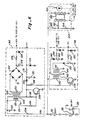
- Power supply invertor 58 is shown in greater detail in FIGURE 6. As shown, the power from batteries 56 (+3 volts) is coupled on lead 104 to one side of primary winding 105 (7 turns) of transformer 106, with the other side of primary winding 105 being connected to the collector of transistor 108. Lead 104 also has bypass capacitor 110 to ground connected thereto, as is two-turn winding 112, which winding is connected to the base of transistor 108 through series connected capacitor 114 and resistor 116 (the base and collector of transistor 108 are also connected through resistor 118).
- Secondary winding 120 (150 turns) of transformer 106 is connected to bridge rectifier 122, with the output from rectifier 122 being the + 50 volt output that is coupled through resistor 124 to the display circuitry (the output side of resistor 124 has Zener diode 126 connected therewith and capacitor 128 is connected at the input side of resistor 124).
- the +5 volt power supply output from section 96 is provided through diode 130 connected to the collector of transistor 108 with diode 130 having resistor 131 connected therewith, with resistor 131 having capacitor 132 and Zener diode 134 to ground connected at opposite sides thereof.
- the primary winding 105 of transformer 106 is also connected through resistor 136 to the base of transistor 138, the collector of which is connected to primary winding 140 (7 turns) of transformer 142 of power supply section 98.
- Secondary winding 144 of transformer 142 is connected with diode 146, the output of which is coupled through resistor 148 as the +30 volt DC output.
- Resistor 148 has a capacitor 149 at one side thereof to ground and Zener diode 150 to ground at the other side.
- the -5 volt power supply is provided through winding 152 (7 turns) of transformer 142 connected through diode 153 and resistor 154, with resistor 153 having capacitor 155 to ground at one side and Zener diode 156 to ground at the other side (i.e., the output side).
- the output from batteries 56 is also coupled to low battery indicator circuitry 100.
- the +3 volt input from the batteries is coupled to pin 8 of integrating circuit 158 (for example an ICL8212CPA), is coupled through resistors 160 and 162 to input 2 of circuit 158, and is coupled through resistor 160 to input 3 of circuity 158, with resistor 164 to ground also being connected to the junction of resistors 160 and 162.
- the low battery output indication is coupled from pin 4 of circuit 158 with light emitting diode (LED) 102 being a typical indicator to indicate, by constant energization of the LED that sufficient power is being supplied, and to include, by interrupted energization of the LED (i.e., by blinking of the LED) that low battery power is being sensed, as is conventional.
- LED light emitting diode
- mixer 68 is an integrated circuit having rate generator 62 and width generator 65 connected thereto, with rate generator 62 being coupled to input 1 through resistor 170 (the junction of which has a capacitor 172 to ground connected therewith).
- the width generator 65 input is coupled to pin 3 through resistor 174 (with capacitor 176 being connected between inputs 2 and 3 of unit 68).
- Mixer 68 receives the high frequency input from high frequency generator 70, which as shown in FIGURE 7, is connected to pin 11 of mixer 68 through resistor 178 and to pin 9 through diode 180 (having resistor 182 to ground connected therewith).
- Pin 11 of mixer 68 also has a capacitor 184 to ground connected therewith, and pin 12 is connected to pin 13 through resistor 186, with pin 13 also having capacitor 188 to ground connected therewith.
- pin 12 is also connected to isolation amplifier 73, the collector of which is connected through resistor 190 to the +5 volt power supply, and diode 192 is connected between pins 6 and 9 of mixer 68.
- the output from mixer 68 is coupled from pin 8 to the base of amplifier 76 through resistor 194.
- the collector of amplifier 76 has the output coupled therefrom through resistor 196 to potentiometers 80 and 82 and to variable resistor 86 (providing DC offset), and the output from the wipers of potentiometers 80 and 82 is commonly coupled to constant current generators 88 and 90, and, more particularly, is coupled to the bases of transistors 198 and 200, the emitters of which are connected to the +30 volt power supply through resistor 202 (with the power supply having a bypass capacitor to ground 204 connected therewith).
- the output from transistor 198 is coupled through resistor 206 and lead 36a to electrode 38a, while the output from transistor 200 is coupled through resistor 208 and lead 36c to electrode 38c.
- Return electrode 38b is coupled through lead 36b and resistor 92 to ground, while electrode 38d is connected through lead 36d to ground.
- FIGURE 8 illustrates the stimulator (i.e., TENS unit 60) applying the output signals to the electrodes, with outputs therefrom being utilized to drive displays 32 and 34, display 32 being the digital display and display 34 being the bar graph display.
- the output taken from electrode 38b is commonly coupled to analog-to-digital (A/D) voltage display driver 212 to drive digital unit 32 and to analog-to-digital (A/D) bar display driver 214 to drive the bar display, with each driver having a calibration potentiometer (potentiometers 216 and 218, respectively, as shown in FIGURE 8) connected therewith.
- Bar graph display driver 214 is shown in greater detail in FIGURE 9. As shown, the input is coupled through variable resistor 222 to pin 5 of analog-to-digital (A/D) convertor and voltage comparator unit 224 (for example an LM3914) with pin 5 being connected to ground through resistor 226, and pins 6 and 7 being connected to ground through resistor 228. Unit 224 operates as a voltage comparator such that increases in voltage above predetermined values cause each output to be successively energized. The outputs from unit 224 are coupled through resistors 230 back to pins 3 and 9 of unit 224, with the outputs also being coupled to exclusive - or circuits 232, 234 and 236 (for example utilizing three Z4686 integrated circuits).
- A/D analog-to-digital
- unit 224 for example an LM3914
- Unit 224 operates as a voltage comparator such that increases in voltage above predetermined values cause each output to be successively energized.
- the outputs from unit 224 are coupled through resistors 230 back
- circuits 232, 234 and 236 are coupled to high voltage driver circuits 238 and 240 (for example ULN2023 integrated circuits) having AC outputs directly coupled to control the display (liquid crystal display) represented by the bars of display 34.
- Resistors 242 are utilized to couple the +50 volt power to circuits 238 and 240.
- double-pole, double-throw switch 246 is provided having switching sections 248 and 250 with switching section 248 connecting the output from transistor 198 to electrode 38a when in the DC position and connecting the output from transistor 198 to electrode 38a through capacitor 252 when in the AC position.
- Switching section 250 is not utilized when in the DC position, but in the AC position connects the output from transistor 198 to electrode 38b through resistor 254. If dual electrodes are utilized, switching would be accomplished in the same manner.
- switch 246 could be manually actuated, but preferably is automatically actuated by means of timer 256. For best operation, it is now felt that the pulsed DC signal should be applied for a period ranging from less than a minute to five minutes, and preferably from one to two minutes, followed by thereafter applying the AC signal.
- FIGURE 11 depicts TENS circuitry unit 60 having an output coupled through 100 ⁇ Fd capacitor 258 to a typical 1000 ohm load resistor 260 (between electrodes 38a and 38b).
- a typical waveform is shown in FIGURE 12A with an enlarged portion (indicated as 12B in FIGURE 12A) of the waveform being shown in FIGURE 12B.
- a typical waveform is shown in FIGURE 12C with an enlarged portion (indicated as 12D in FIGURE 12C) of the waveform being shown in FIGURE 12C.
- the apparatus can include an electrode-connection safety feature to assure proper connection and functioning of the electrode circuitry. As illustrated in FIGURE 11, this feature is implemented by amplifier 262 connected to lead 36b, with the output of amplifier 262 being coupled to Schmitt trigger 264. The output of Schmitt trigger 264 is coupled to low frequency oscillator 266 which provides an output to bar graph display 34 to cause the bar graph display to flash, or blink, (i.e., be intermittently energized) when the electrodes are not properly connected in the circuit or are not properly positioned within the mouth of a patient to complete the circuit.
- this feature is implemented by amplifier 262 connected to lead 36b, with the output of amplifier 262 being coupled to Schmitt trigger 264.
- the output of Schmitt trigger 264 is coupled to low frequency oscillator 266 which provides an output to bar graph display 34 to cause the bar graph display to flash, or blink, (i.e., be intermittently energized) when the electrodes are not properly connected in the circuit or are not properly positioned within the mouth of a patient to
- timer 256 may be connected to Schmitt trigger 264, if desired, so that the timer does not start operation until the electrodes are properly positioned.
- the operator such as the dentist, applies the electrodes inside the mouth of a patient to the gum or the like (the electrode may have a cover over the adhesive which is removed before application of each electrode to the gum or the like).
- the electrodes are self-adhering, and the leads from the electrodes are connected with the main unit of the apparatus.
- the apparatus is then turned on by switch 28 and the dentist selects (or predicts before turning switch 28 on) the threshold intensity level by moving slide bar actuator 30 to the desired position.
- the intensity level is displayed at digital display 32 and slide bar display 34, since at this point, remote controller slide bar actuator 26 is preferably at a minimum level.
- bar graph display 34 will blink if the electrodes are not properly connected, and digital display 32 will blink if a low battery level is sensed. After energization, the apparatus will continue to apply dental anesthesia electrically. The dentist will then perform necessary dental work, and, if needed, the patient during this period can increase the intensity level of the applied electrical signal by adjusting actuation 26 (the intensity level then selected will be displayed by digital display and bar graph display 34).
- the apparatus is turned off by switch 28, and the electrodes are removed by peeling each from the gum or the like.
- this invention provides an improved dental anesthesia device which utilizes an electronic stimulator to provide an output that is applied to a patient through electrodes within the mouth of a patient to effectively preclude sensing of pain by the patient during treatment.
Landscapes
- Health & Medical Sciences (AREA)
- Life Sciences & Earth Sciences (AREA)
- Radiology & Medical Imaging (AREA)
- Engineering & Computer Science (AREA)
- Biomedical Technology (AREA)
- Nuclear Medicine, Radiotherapy & Molecular Imaging (AREA)
- Animal Behavior & Ethology (AREA)
- General Health & Medical Sciences (AREA)
- Public Health (AREA)
- Veterinary Medicine (AREA)
- Heart & Thoracic Surgery (AREA)
- Cardiology (AREA)
- Pain & Pain Management (AREA)
- Biophysics (AREA)
- Electrotherapy Devices (AREA)
Applications Claiming Priority (2)
| Application Number | Priority Date | Filing Date | Title |
|---|---|---|---|
| US07/272,225 US4924880A (en) | 1988-11-16 | 1988-11-16 | Dental anesthesia apparatus |
| US272225 | 1988-11-16 |
Publications (1)
| Publication Number | Publication Date |
|---|---|
| EP0369414A1 true EP0369414A1 (fr) | 1990-05-23 |
Family
ID=23038921
Family Applications (1)
| Application Number | Title | Priority Date | Filing Date |
|---|---|---|---|
| EP89121096A Withdrawn EP0369414A1 (fr) | 1988-11-16 | 1989-11-14 | Appareil d'anesthésie dentaire |
Country Status (3)
| Country | Link |
|---|---|
| US (1) | US4924880A (fr) |
| EP (1) | EP0369414A1 (fr) |
| CA (1) | CA1334597C (fr) |
Cited By (3)
| Publication number | Priority date | Publication date | Assignee | Title |
|---|---|---|---|---|
| WO1994027491A3 (fr) * | 1993-06-02 | 1995-02-02 | Minnesota Mining & Mfg | Electrode pour interventions intra-buccales |
| US5496363A (en) * | 1993-06-02 | 1996-03-05 | Minnesota Mining And Manufacturing Company | Electrode and assembly |
| EP0673660A3 (fr) * | 1994-03-25 | 1996-07-24 | Heinrich W Schramm | Dispositif d'électrodes pour l'anesthésie électronique en site buccal. |
Families Citing this family (79)
| Publication number | Priority date | Publication date | Assignee | Title |
|---|---|---|---|---|
| US6141587A (en) * | 1996-08-19 | 2000-10-31 | Mower Family Chf Treatment Irrevocable Trust | Augmentation of muscle contractility by biphasic stimulation |
| US6343232B1 (en) | 1966-08-19 | 2002-01-29 | Mower Chf Treatment Irrevocable Trust | Augmentation of muscle contractility by biphasic stimulation |
| US6136019A (en) * | 1996-08-19 | 2000-10-24 | Mower Family Chf Treatment Irrevocable Trust | Augmentation of electrical conduction and contractility by biphasic cardiac pacing administered via the cardiac blood pool |
| GB8904998D0 (en) * | 1989-03-04 | 1989-04-19 | Matthews Tony | Anaesthetising apparatus |
| US5284161A (en) * | 1992-11-12 | 1994-02-08 | Karell Manuel L | Snopper-the snoring stopper anti-snoring mouth device |
| US5792187A (en) | 1993-02-22 | 1998-08-11 | Angeion Corporation | Neuro-stimulation to control pain during cardioversion defibrillation |
| US5593432A (en) * | 1993-06-23 | 1997-01-14 | Neuroware Therapy International, Inc. | Method for neurostimulation for pain alleviation |
| US6083250A (en) * | 1995-10-20 | 2000-07-04 | Nexmed, Inc. | Apparatus and method for inhibiting lesion formation by selectively treating the prodromal stage of the lesion with a pulsatile electrical stimulation |
| US5792067A (en) * | 1995-11-21 | 1998-08-11 | Karell; Manuel L. | Apparatus and method for mitigating sleep and other disorders through electromuscular stimulation |
| US6341235B1 (en) * | 1996-08-19 | 2002-01-22 | Mower Chf Treatment Irrevocable Trust | Augmentation of electrical conduction and contractility by biphasic cardiac pacing administered via the cardiac blood pool |
| US6295470B1 (en) * | 1996-08-19 | 2001-09-25 | The Mower Family Chf Treatment Irrevocable Trust | Antitachycardial pacing |
| US6337995B1 (en) | 1996-08-19 | 2002-01-08 | Mower Chf Treatment Irrevocable Trust | Atrial sensing and multiple site stimulation as intervention for atrial fibrillation |
| US7203537B2 (en) | 1996-08-19 | 2007-04-10 | Mr3 Medical, Llc | System and method for breaking reentry circuits by cooling cardiac tissue |
| US6411847B1 (en) | 1996-08-19 | 2002-06-25 | Morton M. Mower | Apparatus for applying cyclic pacing at an average rate just above the intrinsic heart rate |
| US7908003B1 (en) | 1996-08-19 | 2011-03-15 | Mr3 Medical Llc | System and method for treating ischemia by improving cardiac efficiency |
| US8447399B2 (en) * | 1996-08-19 | 2013-05-21 | Mr3 Medical, Llc | System and method for managing detrimental cardiac remodeling |
| US5871506A (en) * | 1996-08-19 | 1999-02-16 | Mower; Morton M. | Augmentation of electrical conduction and contractility by biphasic cardiac pacing |
| US7440800B2 (en) * | 1996-08-19 | 2008-10-21 | Mr3 Medical, Llc | System and method for managing detrimental cardiac remodeling |
| US7840264B1 (en) | 1996-08-19 | 2010-11-23 | Mr3 Medical, Llc | System and method for breaking reentry circuits by cooling cardiac tissue |
| US5925071A (en) * | 1997-06-06 | 1999-07-20 | Story; Craig W. | Method and apparatus for ridding the human body of pathogens |
| US6351674B2 (en) | 1998-11-23 | 2002-02-26 | Synaptic Corporation | Method for inducing electroanesthesia using high frequency, high intensity transcutaneous electrical nerve stimulation |
| US6161044A (en) * | 1998-11-23 | 2000-12-12 | Synaptic Corporation | Method and apparatus for treating chronic pain syndromes, tremor, dementia and related disorders and for inducing electroanesthesia using high frequency, high intensity transcutaneous electrical nerve stimulation |
| US6411845B1 (en) | 1999-03-04 | 2002-06-25 | Mower Chf Treatment Irrevocable Trust | System for multiple site biphasic stimulation to revert ventricular arrhythmias |
| US6758830B1 (en) | 1999-05-11 | 2004-07-06 | Atrionix, Inc. | Catheter positioning system |
| US6332096B1 (en) | 2000-02-16 | 2001-12-18 | Mower Chf Treatment Irrevocable Trust | Augmentation of electrical conduction and contractility by biphasic cardiac pacing |
| JP2002263106A (ja) * | 2001-03-12 | 2002-09-17 | Olympus Optical Co Ltd | 光プローブ装置 |
| US6535767B1 (en) | 2001-08-21 | 2003-03-18 | James W. Kronberg | Apparatus and method for bioelectric stimulation, healing acceleration and pain relief |
| US7228184B2 (en) * | 2003-02-22 | 2007-06-05 | Chester Heath | Viral-inhibiting method |
| CA2530396C (fr) * | 2003-06-24 | 2015-03-24 | Healthonics, Inc. | Appareil et procede de stimulation bioelectrique, d'acceleration de la cicatrisation, de soulagement de la douleur ou de devitalisation d'agents pathogenes |
| US8060220B2 (en) * | 2003-08-05 | 2011-11-15 | Sachiko Liebergesell | Promotion of oral hygiene and treatment of gingivitis, other periodontal problems and oral mal odor with alternating current waveforms and device therefor |
| US7212865B2 (en) * | 2004-05-25 | 2007-05-01 | Philip Cory | Nerve stimulator and method |
| KR200362377Y1 (ko) * | 2004-06-25 | 2004-09-23 | 전언국 | 잇몸전용 저주파자극기 |
| US20060005844A1 (en) * | 2004-07-08 | 2006-01-12 | Coulter George G | Rolling tube apparatus and method for treating a wound |
| US7654825B2 (en) * | 2005-06-03 | 2010-02-02 | Ray Charles D | Dental vibrator and acoustical unit with method for the inhibition of operative pain |
| US8660669B2 (en) * | 2007-09-05 | 2014-02-25 | Biolectrics Llc | Concurrent treatment of oral maladies using direct current electricity |
| US9314321B2 (en) | 2007-09-05 | 2016-04-19 | Biolectrics Llc | Concurrent treatment of oral and systemic maladies in animals using electrical current |
| US9168370B2 (en) | 2007-09-05 | 2015-10-27 | Biolectrics Llc | Concurrent treatment of oral and systemic maladies using direct current electricity |
| US8849407B1 (en) | 2008-01-04 | 2014-09-30 | Yuri P. Danilov | Non-invasive neuromodulation (NINM) for rehabilitation of brain function |
| US8909346B2 (en) * | 2008-02-15 | 2014-12-09 | Mary Ellen S. Chalmers | Frequency specific micocurrent for treatment of dental indications |
| US20110098777A1 (en) | 2009-10-23 | 2011-04-28 | Silverstone Leon M | Method and apparatus for treatment of neurodegenerative diseases including depression, mild cognitive impairment, and dementia |
| US10226586B2 (en) | 2011-05-26 | 2019-03-12 | Pourang Bral | Means and method to painlessly puncture skin |
| US9770560B2 (en) | 2009-11-12 | 2017-09-26 | Pourang Bral | Means and method to administer injections with little or no pain |
| US10973994B2 (en) | 2013-09-16 | 2021-04-13 | Pourang Bral | Means and method to invade skin, mucosa, and underlying tissues with little or no pain |
| EP2560729A1 (fr) | 2010-04-23 | 2013-02-27 | Vallero, Rommel, P. | Analgésie topique utilisant des stimuli électriques et vibrationnels |
| EP2613701A2 (fr) | 2010-09-07 | 2013-07-17 | Innova Medical Design LLC | Systèmes, procédés et dispositifs de réduction de la douleur provoquée par une surveillance de glucose et une administration d'insuline chez des patients diabétiques |
| AU2015204825A1 (en) | 2014-01-07 | 2016-07-28 | Animal Oralectrics Llc | Treatment of oral maladies using electrical current |
| US9072889B1 (en) * | 2014-12-03 | 2015-07-07 | Neurohabilitation Corporation | Systems for providing non-invasive neurorehabilitation of a patient |
| US9993640B2 (en) | 2014-12-03 | 2018-06-12 | Neurohabilitation Corporation | Devices for delivering non-invasive neuromodulation to a patient |
| USD759830S1 (en) | 2014-12-03 | 2016-06-21 | Neurohabilitation Corporation | Non-invasive neurostimulation device |
| US9227051B1 (en) | 2014-12-03 | 2016-01-05 | Neurohabilitation Corporation | Devices for delivering non-invasive neuromodulation to a patient |
| USD749746S1 (en) | 2014-12-03 | 2016-02-16 | Neurohabilitation Corporation | Non-invasive neurostimulation device |
| US9283377B1 (en) | 2014-12-03 | 2016-03-15 | Neurohabilitation Corporation | Devices for delivering non-invasive neuromodulation to a patient |
| USD750265S1 (en) | 2014-12-03 | 2016-02-23 | Neurohabilitation Corporation | Non-invasive neurostimulation device |
| US9981127B2 (en) | 2014-12-03 | 2018-05-29 | Neurohabilitation Corporation | Systems and methods for providing non-invasive neurorehabilitation of a patient |
| USD753316S1 (en) | 2014-12-03 | 2016-04-05 | Neurohabilitation Corporation | Non-invasive neurostimulation device |
| US9272133B1 (en) | 2014-12-03 | 2016-03-01 | Neurohabilitation Corporation | Methods of manufacturing devices for the neurorehabilitation of a patient |
| US9415210B2 (en) | 2014-12-03 | 2016-08-16 | Neurohabilitation Corporation | Methods of manufacturing devices for the neurorehabilitation of a patient |
| USD751722S1 (en) | 2014-12-03 | 2016-03-15 | Neurohabilitation Corporation | Non-invasive neurostimulation device |
| US9415209B2 (en) | 2014-12-03 | 2016-08-16 | Neurohabilitation Corporation | Methods of manufacturing devices for the neurorehabilitation of a patient |
| USD760397S1 (en) | 2014-12-03 | 2016-06-28 | Neurohabilitation Corporation | Non-invasive neurostimulation device |
| USD750264S1 (en) | 2014-12-03 | 2016-02-23 | Neurohabilitation Corporation | Non-invasive neurostimulation device |
| US9656060B2 (en) | 2014-12-03 | 2017-05-23 | Neurohabilitation Corporation | Methods of manufacturing devices for the neurorehabilitation of a patient |
| USD752766S1 (en) | 2014-12-03 | 2016-03-29 | Neurohabilitation Corporation | Non-invasive neurostimulation device |
| USD753315S1 (en) | 2014-12-03 | 2016-04-05 | Neurohabilitation Corporation | Non-invasive neurostimulation device |
| USD750268S1 (en) | 2014-12-03 | 2016-02-23 | Neurohabilitation Corporation | Non-invasive neurostimulation device |
| USD751214S1 (en) | 2014-12-03 | 2016-03-08 | Neurohabilitation Corporation | Non-invasive neurostimulation device |
| US9616222B2 (en) | 2014-12-03 | 2017-04-11 | Neurohabilitation Corporation | Systems for providing non-invasive neurorehabilitation of a patient |
| USD750266S1 (en) | 2014-12-03 | 2016-02-23 | Neurohabilitation Corporation | Non-invasive neurostimulation device |
| USD751213S1 (en) | 2014-12-03 | 2016-03-08 | Neurohabilitation Corporation | Non-invasive neurostimulation device |
| USD750267S1 (en) | 2014-12-03 | 2016-02-23 | Neurohabilitation Corporation | Non-invasive neurostimulation device |
| USD752236S1 (en) | 2014-12-03 | 2016-03-22 | Neurohabilitation Corporation | Non-invasive neurostimulation device |
| US9789306B2 (en) | 2014-12-03 | 2017-10-17 | Neurohabilitation Corporation | Systems and methods for providing non-invasive neurorehabilitation of a patient |
| USD750794S1 (en) | 2014-12-03 | 2016-03-01 | Neurohabilitation Corporation | Non-invasive neurostimulation device |
| US11103696B2 (en) | 2015-05-05 | 2021-08-31 | Cosmo Haralambidis | Device for electrical stimulation of peridontal complex and surrounding tissue |
| EP3291880B1 (fr) | 2015-05-05 | 2021-07-07 | Haralambidis, Cosmo | Dispositif pour la stimulation électrique du complexe parodontal et du tissu environnant |
| WO2017173335A1 (fr) * | 2016-03-31 | 2017-10-05 | University Of Utah Research Foundation | Stimulation nerveuse électronique |
| WO2019051392A2 (fr) | 2017-09-08 | 2019-03-14 | Alacrity, Inc. | Procédés et appareil pour induire électriquement un macro-courant net à travers des membranes de cellules neuronales |
| US11141593B2 (en) * | 2019-12-06 | 2021-10-12 | Y-Brain Inc. | Device and method modulating nerve of a patient by providing electrical stimulation |
| JP7843746B2 (ja) | 2020-07-28 | 2026-04-10 | バイオレクトリクス エルエルシー | 口腔内電気刺激に関連するシステムおよび方法 |
Citations (6)
| Publication number | Priority date | Publication date | Assignee | Title |
|---|---|---|---|---|
| FR2047171A5 (fr) * | 1969-05-02 | 1971-03-12 | Sybron Corp | |
| FR2338712A2 (fr) * | 1976-01-21 | 1977-08-19 | Mo Oblastnoi I Aku | Dispositif agissant sur le systeme nerveux central au moyen d'impulsions de courant |
| EP0111229A2 (fr) * | 1982-12-08 | 1984-06-20 | Neurotronic (1981) Ltee. | Dispositif pour la stimulation électrique des nerfs |
| EP0160753A1 (fr) * | 1983-01-25 | 1985-11-13 | International Medical Machines, Inc. | Dispositif et procédé d'acupuncture électrothérapeutique |
| US4676257A (en) * | 1984-12-20 | 1987-06-30 | Pain Prevention, Inc. | Dental anesthesia apparatus |
| US4782837A (en) * | 1986-04-25 | 1988-11-08 | Hogan Dennis E | Dental analgesia method and apparatus |
Family Cites Families (9)
| Publication number | Priority date | Publication date | Assignee | Title |
|---|---|---|---|---|
| JPS54119792A (en) * | 1978-03-03 | 1979-09-17 | Iriyou Kougaku Kenkiyuushiyo K | Electric stimulation device for removing pain |
| US4177819A (en) * | 1978-03-30 | 1979-12-11 | Kofsky Harvey I | Muscle stimulating apparatus |
| CA1153427A (fr) * | 1978-12-11 | 1983-09-06 | Patrick T. Cahalan | Electrode auto-collable |
| US4248247A (en) * | 1979-06-28 | 1981-02-03 | Med General, Inc. | Low cost post-operative electrode |
| US4503863A (en) * | 1979-06-29 | 1985-03-12 | Katims Jefferson J | Method and apparatus for transcutaneous electrical stimulation |
| US4539996A (en) * | 1980-01-23 | 1985-09-10 | Minnesota Mining And Manufacturing Company | Conductive adhesive and biomedical electrode |
| US4509520A (en) * | 1982-02-22 | 1985-04-09 | Biolectron, Inc. | Electrical stimulating apparatus |
| US4784142A (en) * | 1984-01-09 | 1988-11-15 | Pain Suppression Labs, Inc. | Methodology for electronic dental analgesia |
| US4919139A (en) * | 1985-04-03 | 1990-04-24 | Medicomex S.A. | Electrical neuromuscular stimulation device |
-
1988
- 1988-11-16 US US07/272,225 patent/US4924880A/en not_active Expired - Lifetime
-
1989
- 1989-09-25 CA CA000612754A patent/CA1334597C/fr not_active Expired - Fee Related
- 1989-11-14 EP EP89121096A patent/EP0369414A1/fr not_active Withdrawn
Patent Citations (6)
| Publication number | Priority date | Publication date | Assignee | Title |
|---|---|---|---|---|
| FR2047171A5 (fr) * | 1969-05-02 | 1971-03-12 | Sybron Corp | |
| FR2338712A2 (fr) * | 1976-01-21 | 1977-08-19 | Mo Oblastnoi I Aku | Dispositif agissant sur le systeme nerveux central au moyen d'impulsions de courant |
| EP0111229A2 (fr) * | 1982-12-08 | 1984-06-20 | Neurotronic (1981) Ltee. | Dispositif pour la stimulation électrique des nerfs |
| EP0160753A1 (fr) * | 1983-01-25 | 1985-11-13 | International Medical Machines, Inc. | Dispositif et procédé d'acupuncture électrothérapeutique |
| US4676257A (en) * | 1984-12-20 | 1987-06-30 | Pain Prevention, Inc. | Dental anesthesia apparatus |
| US4782837A (en) * | 1986-04-25 | 1988-11-08 | Hogan Dennis E | Dental analgesia method and apparatus |
Cited By (3)
| Publication number | Priority date | Publication date | Assignee | Title |
|---|---|---|---|---|
| WO1994027491A3 (fr) * | 1993-06-02 | 1995-02-02 | Minnesota Mining & Mfg | Electrode pour interventions intra-buccales |
| US5496363A (en) * | 1993-06-02 | 1996-03-05 | Minnesota Mining And Manufacturing Company | Electrode and assembly |
| EP0673660A3 (fr) * | 1994-03-25 | 1996-07-24 | Heinrich W Schramm | Dispositif d'électrodes pour l'anesthésie électronique en site buccal. |
Also Published As
| Publication number | Publication date |
|---|---|
| US4924880A (en) | 1990-05-15 |
| CA1334597C (fr) | 1995-02-28 |
Similar Documents
| Publication | Publication Date | Title |
|---|---|---|
| US4924880A (en) | Dental anesthesia apparatus | |
| US4515168A (en) | Clamp-on nerve stimulator and locator | |
| US4141367A (en) | Cardiac electrode/pacer system analyzer | |
| US5800458A (en) | Compliance monitor for monitoring applied electrical stimulation | |
| US4962766A (en) | Nerve locator and stimulator | |
| CA2797690C (fr) | Systemes et procedes pour une stimulation electrique percutanee | |
| US5853373A (en) | Bi-level charge pulse apparatus to facilitate nerve location during peripheral nerve block procedures | |
| CA2732732C (fr) | Ensembles et systemes portatifs permettant d'apporter une neurostimulation fonctionnelle ou therapeutique et procedes associes | |
| US4157087A (en) | Peripheral nerve stimulator | |
| US5836990A (en) | Method and apparatus for determining electrode/tissue contact | |
| JP4162813B2 (ja) | イオントフォレーシス装置 | |
| MXPA97005839A (en) | Two level loading impulse apparatus to facilitate nerve localization during peripheral nerve blocking procedures | |
| JPS6229064B2 (fr) | ||
| US20030199782A1 (en) | Apparatus and method for stimulating human tissue | |
| AU607925B2 (en) | Programmable constant current source transdermal drug delivery system | |
| EP0483150B1 (fr) | Dispositif de localisation pour l'acupuncture | |
| AU2011248594A1 (en) | Systems and methods for percutaneous electrical stimulation | |
| JP2000507472A (ja) | 触感刺激発生器をもった電気搬送薬品給付装置 | |
| EP2379167B1 (fr) | Dispositif de vérification de la sortie électrique d un dispositif de thérapie par micro-courants | |
| US4197641A (en) | Electrical pulp testing instrument | |
| US20240033500A1 (en) | Evaluating method for useful lifespan of conductive gel and non-implantable electrical stimulation device | |
| JPH1080484A (ja) | 神経の電気的刺激用針組立体 | |
| EP1163926A1 (fr) | Dispositif d'ionophorese | |
| JP3007267U (ja) | 耳のツボ自動探測による刺激装置 | |
| KR200445363Y1 (ko) | 수술용 신경 자극장치 |
Legal Events
| Date | Code | Title | Description |
|---|---|---|---|
| PUAI | Public reference made under article 153(3) epc to a published international application that has entered the european phase |
Free format text: ORIGINAL CODE: 0009012 |
|
| AK | Designated contracting states |
Kind code of ref document: A1 Designated state(s): AT BE CH DE ES FR GB GR IT LI LU NL SE |
|
| 17P | Request for examination filed |
Effective date: 19901122 |
|
| 17Q | First examination report despatched |
Effective date: 19930618 |
|
| STAA | Information on the status of an ep patent application or granted ep patent |
Free format text: STATUS: THE APPLICATION IS DEEMED TO BE WITHDRAWN |
|
| 18D | Application deemed to be withdrawn |
Effective date: 19940502 |