EP0369421A2 - Protection pour prise de force - Google Patents
Protection pour prise de force Download PDFInfo
- Publication number
- EP0369421A2 EP0369421A2 EP89121131A EP89121131A EP0369421A2 EP 0369421 A2 EP0369421 A2 EP 0369421A2 EP 89121131 A EP89121131 A EP 89121131A EP 89121131 A EP89121131 A EP 89121131A EP 0369421 A2 EP0369421 A2 EP 0369421A2
- Authority
- EP
- European Patent Office
- Prior art keywords
- housing part
- pto shaft
- protective
- pto
- shaped housing
- Prior art date
- Legal status (The legal status is an assumption and is not a legal conclusion. Google has not performed a legal analysis and makes no representation as to the accuracy of the status listed.)
- Withdrawn
Links
Images

Classifications
-
- A—HUMAN NECESSITIES
- A01—AGRICULTURE; FORESTRY; ANIMAL HUSBANDRY; HUNTING; TRAPPING; FISHING
- A01B—SOIL WORKING IN AGRICULTURE OR FORESTRY; PARTS, DETAILS, OR ACCESSORIES OF AGRICULTURAL MACHINES OR IMPLEMENTS, IN GENERAL
- A01B71/00—Construction or arrangement of setting or adjusting mechanisms, of implement or tool drive or of power take-off; Means for protecting parts against dust, or the like; Adapting machine elements to or for agricultural purposes
- A01B71/08—Means for protecting against dust or the like, or for cleaning agricultural implements
-
- F—MECHANICAL ENGINEERING; LIGHTING; HEATING; WEAPONS; BLASTING
- F16—ENGINEERING ELEMENTS AND UNITS; GENERAL MEASURES FOR PRODUCING AND MAINTAINING EFFECTIVE FUNCTIONING OF MACHINES OR INSTALLATIONS; THERMAL INSULATION IN GENERAL
- F16D—COUPLINGS FOR TRANSMITTING ROTATION; CLUTCHES; BRAKES
- F16D3/00—Yielding couplings, i.e. with means permitting movement between the connected parts during the drive
- F16D3/84—Shrouds, e.g. casings, covers; Sealing means specially adapted therefor
- F16D3/841—Open covers, e.g. guards for agricultural p.t.o. shafts
Definitions
- the invention relates to a protective cover for preventing contact with at least one freely ending, rotating part, in particular PTO shaft of an agricultural tractor, with a U-shaped housing part, the base leg and free leg of which are aligned essentially parallel to the rotating part in a first protective position and this enclose from three sides, and with an axis running perpendicular to the rotating part and parallel to the base leg surface, about which the U-shaped housing part can be pivoted.
- a PTO shaft is particularly suitable as a freely ending, rotating part. This is the end piece of a drive shaft, for example an agricultural tractor for transmitting the movement to an implement.
- the PTO shaft usually protrudes freely from the gearbox.
- the PTO shaft In order to avoid accidents, the PTO shaft must be protected in accordance with the safety regulations by a protective housing attached to the drive unit, for example the tractor. The required dimensions of the protective housing are defined by the safety regulations. In tractors, the PTO shaft must be covered at least on the top and on both sides.
- a protective cover has become known from DE-PS 34 02 065, in which a protective shield can be opened up quickly and without the use of tools in order to facilitate the assembly of implements with a PTO drive.
- the protective shield is U-shaped trained and covers the PTO shaft from the top and sides.
- the legs (side parts) of the U-shaped protective shield are mounted in a horizontal swivel bearing that runs transversely to the PTO.
- the protective shield can be swiveled around this bearing, so that the base leg (upper part) of the U-shaped protective shield lying at the top in the normal position can be folded in the direction of the gearbox housing.
- an additional, non-rotating protective cap is provided which completely covers the PTO and which covers the protruding PTO when the PTO is not in use. Since the protective housing attached to the gearbox housing is open towards the front of the PTO shaft, the protective cap serves to protect against contact in the event that no implement is connected to the PTO shaft. The protective cap must be attached or removed when installing a machine. A storage device for the protective cap must be created at a suitable location near the PTO. The risk of losing the protective cap must be taken into account.
- the housing part can be pivoted about its axis from its first protective position such that the base leg assumes a position in front of the outwardly facing end face of the PTO shaft in a second protective position.
- the base leg is oriented essentially vertically.
- the housing part preferably contains a further cover part, which lies between the free legs and adjoins the base leg.
- this cover part lies parallel to the PTO shaft and covers it from above.
- This inventive design of a PTO shaft protection ensures that when the housing part is folded up (first protective position) and the implement connected to the PTO shaft, the PTO shaft is covered from above and laterally in accordance with the regulations. If, on the other hand, no implement is connected to the PTO, the housing part can be folded down (second protective position). In this position, the PTO shaft is covered by the protective cover from above, from both sides and on its end face, so that the safety regulations are also observed in this position. An additional protective cap is no longer required.
- an essentially vertically oriented cheek can be fastened on both sides of the PTO shaft to the housing receiving the PTO shaft, in particular a gear housing.
- the cheeks are designed so that they ensure sufficient lateral coverage of the PTO.
- the cheeks take up the pivot axes about which the U-shaped housing part can be pivoted. This configuration also ensures reliable lateral coverage of the PTO if the side legs of the U-shaped housing part are not designed so long that they completely cover the PTO laterally.
- Bolts are preferably used as bearings for the swivel axis.
- a horizontally oriented protective shield is arranged below the PTO shaft on the housing receiving the PTO shaft, in particular transmission housing, which covers the PTO shaft from below, in order to thereby achieve all-round coverage of the PTO shaft, in particular in the second protective position.
- a cheek 12, 14 is arranged on each side of the horizontally oriented PTO shaft 10.
- the cheeks 12, 14 consist of steel sheets which are aligned vertically.
- a vertically extending end face 16, 18 of the cheeks 12, 14 is attached to a gear housing, not shown.
- the PTO shaft 10 also emerges from this transmission housing.
- the cheeks 12, 14 cover the PTO 10 laterally and meet the protective regulations according to which the lateral access to the PTO 10 is to be prevented.
- the two cheeks 12, 14 are rigidly connected to one another in the region of their lower edges by a protective shield 20.
- This protective shield covers the PTO shaft 10 from below.
- Such a protective shield 20 is not provided for the first protective position in the protective regulations for agricultural tractors. This protective shield 20 can therefore be dispensed with if it makes access to the PTO shaft 10 unnecessarily difficult for the assembly of work equipment.
- a U-shaped housing part 22 is arranged in the upper region between the cheeks 12, 14. 1, the base leg 24 of the housing part 22 lies horizontally above the PTO shaft 10 and covers it from above.
- the two free legs 26, 28 extend vertically downward and are parallel to the cheeks 12, 14.
- the housing part 22 is rotatably mounted between the cheeks 12, 14 by means of bolts 30, 32 which are only indicated.
- the pivot axis 34 is above the PTO 10. Due to this pivot bearing, the housing part 22 can be folded down.
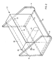
- the folded-down position of the housing part 22 can be seen in FIG. 2.
- the base leg 24 is oriented vertically and lies in front of the front side of the PTO shaft 10.
- a cover part 36 is rigidly connected to the housing part 22 in the upper region thereof.
- the cover part 36 is formed horizontally as shown in FIG. 2 and angled downward toward the gear housing side.
- the horizontal part of the cover part 36 adjoins the base leg 24.
- the PTO shaft 10 is covered from above, even when the housing part 22 is pivoted down, so that no intervention in the PTO shaft 10 is possible from here.
- the PTO shaft is covered on all sides by parts of the protective cover, so that the protective regulations are observed.
Landscapes
- Engineering & Computer Science (AREA)
- General Engineering & Computer Science (AREA)
- Mechanical Engineering (AREA)
- Life Sciences & Earth Sciences (AREA)
- Soil Sciences (AREA)
- Environmental Sciences (AREA)
- Arrangement And Driving Of Transmission Devices (AREA)
Applications Claiming Priority (2)
| Application Number | Priority Date | Filing Date | Title |
|---|---|---|---|
| DE3838803 | 1988-11-17 | ||
| DE3838803A DE3838803A1 (de) | 1988-11-17 | 1988-11-17 | Zapfwellenschutz |
Publications (2)
| Publication Number | Publication Date |
|---|---|
| EP0369421A2 true EP0369421A2 (fr) | 1990-05-23 |
| EP0369421A3 EP0369421A3 (fr) | 1991-08-14 |
Family
ID=6367282
Family Applications (1)
| Application Number | Title | Priority Date | Filing Date |
|---|---|---|---|
| EP19890121131 Withdrawn EP0369421A3 (fr) | 1988-11-17 | 1989-11-15 | Protection pour prise de force |
Country Status (3)
| Country | Link |
|---|---|
| EP (1) | EP0369421A3 (fr) |
| DE (1) | DE3838803A1 (fr) |
| FI (1) | FI895445A7 (fr) |
Cited By (2)
| Publication number | Priority date | Publication date | Assignee | Title |
|---|---|---|---|---|
| US20090197689A1 (en) * | 2008-01-15 | 2009-08-06 | Franz Sauermann | Protection device, in particular power take- off shaft protection, for an end piece of a shaft |
| CN116691337A (zh) * | 2023-07-07 | 2023-09-05 | 潍坊锦伟农业装备有限公司 | 一种可对方向进行切换的拖拉机动力输出装置 |
Families Citing this family (1)
| Publication number | Priority date | Publication date | Assignee | Title |
|---|---|---|---|---|
| DE10222005B4 (de) * | 2002-05-17 | 2005-04-21 | Fritz Sperber Gmbh & Co. | Schutzeinrichtung für das Endstück der Zapfwelle eines Traktors |
Family Cites Families (4)
| Publication number | Priority date | Publication date | Assignee | Title |
|---|---|---|---|---|
| US4008583A (en) * | 1975-08-21 | 1977-02-22 | Deere & Company | Swingable shield assembly for tractor power take-off |
| FI65039C (fi) * | 1982-02-18 | 1984-03-12 | Valmet Oy | Skyddsanordning foer anslutning till bakaenden av en traktorstomme |
| DE3402065C1 (de) * | 1984-01-21 | 1985-04-18 | Deere & Co., Moline, Ill., US, Niederlassung Deere & Co. European Office, 6800 Mannheim | Schutzeinrichtung zum Verhindern der Beruehrung mindestens eines sich drehenden Teiles |
| US4761152A (en) * | 1987-05-18 | 1988-08-02 | J. I. Case Company | Foldable power take-off shaft shield |
-
1988
- 1988-11-17 DE DE3838803A patent/DE3838803A1/de active Granted
-
1989
- 1989-11-15 FI FI895445A patent/FI895445A7/fi not_active Application Discontinuation
- 1989-11-15 EP EP19890121131 patent/EP0369421A3/fr not_active Withdrawn
Cited By (2)
| Publication number | Priority date | Publication date | Assignee | Title |
|---|---|---|---|---|
| US20090197689A1 (en) * | 2008-01-15 | 2009-08-06 | Franz Sauermann | Protection device, in particular power take- off shaft protection, for an end piece of a shaft |
| CN116691337A (zh) * | 2023-07-07 | 2023-09-05 | 潍坊锦伟农业装备有限公司 | 一种可对方向进行切换的拖拉机动力输出装置 |
Also Published As
| Publication number | Publication date |
|---|---|
| DE3838803C2 (fr) | 1991-02-14 |
| FI895445A7 (fi) | 1990-05-18 |
| FI895445A0 (fi) | 1989-11-15 |
| EP0369421A3 (fr) | 1991-08-14 |
| DE3838803A1 (de) | 1990-05-23 |
Similar Documents
| Publication | Publication Date | Title |
|---|---|---|
| DE69316145T2 (de) | Mähmaschine mit Antriebsvorrichtung für Aufbereitungswalzen | |
| DE3149873C2 (fr) | ||
| EP0073359B1 (fr) | Dispositif de verrouillage pour faucheuse | |
| EP0150742B1 (fr) | Dispositif protecteur en forme d'un écran de protection pour couvrir une prise de force | |
| DE69511739T2 (de) | Kreiselmäher mit Mähbalken und Traggestell | |
| DE3102598C2 (fr) | ||
| EP0324930A2 (fr) | Broyeur à galets | |
| EP1029436A2 (fr) | Fixation, faucheuse et véhicule resp. appareil de travail | |
| DE60023290T2 (de) | Abnehmbare absturzsicherung | |
| DE60033110T2 (de) | Verstellbare Schutzvorrichtung für drehende Welle | |
| DE2453171C3 (de) | Vorrichtung zum federnden befestigen von verschwenkbar gelagerten zinken, armen od. dgl | |
| DE19521067A1 (de) | Mähscheibe mit Klingenbefestigung für Rotationsmähwerk | |
| EP4046879B1 (fr) | Dispositif de protection pour une face avant de cabine de véhicule de travail | |
| DE102021121600B4 (de) | Schwenkanordnung für eine Schutzscheibe eines Helmes | |
| EP0369421A2 (fr) | Protection pour prise de force | |
| DE68920470T2 (de) | Mähmaschine. | |
| DE2538435A1 (de) | Feldhaecksler mit messertrommel und messerleiste | |
| EP0343451B1 (fr) | Couvercle de protection pour arbre d'accouplement | |
| DE69210682T2 (de) | Verbesserte Mähmaschine | |
| DE10222005B4 (de) | Schutzeinrichtung für das Endstück der Zapfwelle eines Traktors | |
| DE2023273A1 (de) | Mähwerk | |
| DE2751160A1 (de) | Bodenbearbeitungsgeraet mit rotierenden werkzeugen, insbesondere kreiselegge | |
| CH687771A5 (de) | Bodenbearbeitungsgeraet mit Totmannsicherung. | |
| DE4141184C1 (en) | Agricultural tractor-mower attachment - has front cutter unit on front hitch, rotatably mounted on frame at right angles to travel | |
| EP3783178B1 (fr) | Porte |
Legal Events
| Date | Code | Title | Description |
|---|---|---|---|
| PUAI | Public reference made under article 153(3) epc to a published international application that has entered the european phase |
Free format text: ORIGINAL CODE: 0009012 |
|
| AK | Designated contracting states |
Kind code of ref document: A2 Designated state(s): AT BE CH DE ES FR GB IT LI |
|
| 17P | Request for examination filed |
Effective date: 19901114 |
|
| PUAL | Search report despatched |
Free format text: ORIGINAL CODE: 0009013 |
|
| AK | Designated contracting states |
Kind code of ref document: A3 Designated state(s): AT BE CH DE ES FR GB IT LI |
|
| STAA | Information on the status of an ep patent application or granted ep patent |
Free format text: STATUS: THE APPLICATION HAS BEEN WITHDRAWN |
|
| 18W | Application withdrawn |
Withdrawal date: 19911107 |