EP0369523A2 - Système de télévision haute définition à composantes analogiques multiplexées temporellement (HDMAC) - Google Patents
Système de télévision haute définition à composantes analogiques multiplexées temporellement (HDMAC) Download PDFInfo
- Publication number
- EP0369523A2 EP0369523A2 EP89202819A EP89202819A EP0369523A2 EP 0369523 A2 EP0369523 A2 EP 0369523A2 EP 89202819 A EP89202819 A EP 89202819A EP 89202819 A EP89202819 A EP 89202819A EP 0369523 A2 EP0369523 A2 EP 0369523A2
- Authority
- EP
- European Patent Office
- Prior art keywords
- line
- luminance
- lines
- interlaced
- signal
- Prior art date
- Legal status (The legal status is an assumption and is not a legal conclusion. Google has not performed a legal analysis and makes no representation as to the accuracy of the status listed.)
- Withdrawn
Links
- 230000006835 compression Effects 0.000 claims description 21
- 238000007906 compression Methods 0.000 claims description 21
- 230000005540 biological transmission Effects 0.000 claims description 16
- 238000001914 filtration Methods 0.000 claims description 14
- 238000000034 method Methods 0.000 claims description 11
- 239000000306 component Substances 0.000 claims 50
- 230000000750 progressive effect Effects 0.000 description 12
- 230000006870 function Effects 0.000 description 6
- 230000002123 temporal effect Effects 0.000 description 6
- 238000001228 spectrum Methods 0.000 description 5
- 238000006243 chemical reaction Methods 0.000 description 4
- 230000008569 process Effects 0.000 description 4
- 230000000007 visual effect Effects 0.000 description 4
- 238000009795 derivation Methods 0.000 description 3
- 230000003044 adaptive effect Effects 0.000 description 2
- 230000008859 change Effects 0.000 description 2
- 230000000694 effects Effects 0.000 description 2
- 230000004044 response Effects 0.000 description 2
- 230000002441 reversible effect Effects 0.000 description 2
- 230000001934 delay Effects 0.000 description 1
- 238000010586 diagram Methods 0.000 description 1
- 229910003460 diamond Inorganic materials 0.000 description 1
- 239000010432 diamond Substances 0.000 description 1
- 230000002349 favourable effect Effects 0.000 description 1
- 230000004048 modification Effects 0.000 description 1
- 238000012986 modification Methods 0.000 description 1
- 230000008054 signal transmission Effects 0.000 description 1
- 239000013598 vector Substances 0.000 description 1
Images



Classifications
-
- H—ELECTRICITY
- H04—ELECTRIC COMMUNICATION TECHNIQUE
- H04N—PICTORIAL COMMUNICATION, e.g. TELEVISION
- H04N7/00—Television systems
- H04N7/12—Systems in which the television signal is transmitted via one channel or a plurality of parallel channels, the bandwidth of each channel being less than the bandwidth of the television signal
- H04N7/122—Systems in which the television signal is transmitted via one channel or a plurality of parallel channels, the bandwidth of each channel being less than the bandwidth of the television signal involving expansion and subsequent compression of a signal segment, e.g. a frame, a line
-
- H—ELECTRICITY
- H04—ELECTRIC COMMUNICATION TECHNIQUE
- H04N—PICTORIAL COMMUNICATION, e.g. TELEVISION
- H04N11/00—Colour television systems
- H04N11/24—High-definition television systems
-
- H—ELECTRICITY
- H04—ELECTRIC COMMUNICATION TECHNIQUE
- H04N—PICTORIAL COMMUNICATION, e.g. TELEVISION
- H04N7/00—Television systems
- H04N7/015—High-definition television systems
-
- H—ELECTRICITY
- H04—ELECTRIC COMMUNICATION TECHNIQUE
- H04N—PICTORIAL COMMUNICATION, e.g. TELEVISION
- H04N7/00—Television systems
- H04N7/015—High-definition television systems
- H04N7/0152—High-definition television systems using spatial or temporal subsampling
- H04N7/0155—High-definition television systems using spatial or temporal subsampling using pixel blocks
Definitions
- the instant invention relates to the transmission and reception of high definition television signals and, more specifically, to transmission of high definition television signals in a multiplexed analog components (MAC) format.
- MAC multiplexed analog components
- the bandwidth of a television signal is a function of the spatial (horizontal, vertical) and temporal resolution to be contained in the signal. As increased resolution is desired in either the vertical, horizontal or temporal directions, the bandwidth of the signal must be increased.
- High definition television (HDTV) signals contain considerably more resolution than, for example, standard NTSC encoded signals.
- various ways have been proposed to generate and transmit HDTV signals, some of which are compatible to a greater or lesser degree with NTSC receivers.
- United States Patent US-A 4,694,338 (PHA 21,323) describes a system for transmitting an HDTV signal using two separate signals, one of which is fully compatible with existing NTSC receiving equipment and the other containing enhancement information which, when combined with the NTSC compatible signal in a specially designed receiver, reassembles the HDTV signal.
- United States Patent US-A 4,794,447 (PHA 21,352) describes an apparatus for encoding HDTV signals of different formats, both progressive and interlaced, as time multiplexed analog components (MAC) multiplexed onto a line having a period which equals a single NTSC line (i.e. 63.555 ⁇ sec.)
- MAC time multiplexed analog components
- the international application describes HDMAC-60 encoding and decoding equipment for use with a source signal which is progressively scanned with a 59.94 HZ frame rate, featuring 525 lines in each field and a 16:9 aspect ratio.
- the HDMAC-60 signal can carry video information with a spatial resolution of at least 480 TV lines/picture height (TVL/PH) in the vertical direction and the horizontal equivalent of 495 TVL/PH resolution in the horizontal direction, if derived from a high line rate studio signal such as 1050 lines, 2:1 interlaced, a system for encoding, transmitting and decoding such a signal using a HDMAC-60 like line format, so as to accurately recreate the high definition 1050 2:1 source signal at the receiver, has not been described heretofore.
- TVL/PH TV lines/picture height
- an apparatus for decoding a line signal received over a channel having a channel bandwidth and comprising a plurality of time multiplexed signal packets comprising at least first and second luminance components having first and second time compression ratios, and a plurality of line subtraction components said apparatus comprising: means for demultiplexing said line signal to separate said signal packets to obtain interlaced luminance component fields having a first number of lines from said luminance components and interlaced line subtraction component fields having substantially said first number of lines from line subtraction components; and means coupled to said demultiplexing means for combining said interlaced luminance component fields and said interlaced line subtraction component fields to provide interlaced luminance signal fields having a second number of lines which is substantially twice said first number of lines.
- an interlaced HDTV source signal for example 1050 lines, 2:1 interlaced
- a MAC signal is converted to, and transmitted as, a MAC signal and decoded back to an interlaced signal substantially without geometric distortion.
- the MAC signal is transcodable to NTSC, 1050 2:1 HDTV, and 525 1:1 HDTV.
- temporal update rates are represented for simplicity as fractions of 60 Hz, whereas the actual system is based on a 59.94 Hz temporal update for compatibility with NTSC.
- HDMAC-1050 is a time multiplexed analog components high definition television system that has an input/output format of 1050 lines; 2:1 interlaced with a field rate of 59.94 Hz and an aspect ratio of 16:9.
- certain signal processing steps and hardware used in performing those steps resemble the method and HDMAC-60 hardware disclosed in the above-mentioned international patent application WO 89/01273 (PHA 21,387) which is incorporated by reference herein, several filtering operations unique and necessary to the HDMAC-1050 system are described herein. The detailed structure of the HDMAC-60 signal is described fully in the international application and therefore will not be repeated herein.
- the scanning structure for the source signal is depicted in Figure 1. This signal can deliver nominally 650 television lines of vertical resolution per picture height (TVL/PH).
- HDMAC-1050 and HDMAC-60 are the same. That is, both formats deliver 525 television lines every 50.94-th of a second.
- the HDMAC-1050 structure is interlaced, which means that for an image, fields one and two are offset. This offers the potential for increased vertical resolution over that provided by HDMAC-60.
- HDMAC-1050 will also group the luminance lines into units of four lines. In the HDMAC-1050 format however two of the four lines are transmitted in the form of a "line subtraction” (LS) signal that is similar to the "line differential" signal in HDMAC-60 (lines LD2 and LD4). A wideband luminance line like the HDMAC-60 line Y3, and a narrowband luminance line like the HDMAC-60 line Y1 are also transmitted.
- LS line subtraction
- the 1050 2:1 source scanning structure is converted to 525 lines 1:1 using a reversible process and then further encoded using a HDMAC-60 like superline format. The algorithm chosen to perform this function will be described below.
- the first step in the HDMAC-1050 process is to convert the 1050 2:1 interlaced image to a 525 1:1 progressive image, using an algorithm that will allow the 1050 2:1 interlaced image to be faithfully reconstructed at the HDMAC-1050 receiver.
- This procedure is initiated as shown in Figure 2, where the odd lines x, x+2, x+4 are 525 source lines from odd field S1 and the even lines y, y+2, y+4 are 525 interlaced lines from even field S2.
- the lines of the first (odd) field (1, 3, 5, ..., 1049) are vertically filtered according to the filter function: (1/4)x + (3/4) (x+2)
- the lines of the second (even) field are vertically filtered according to the similar filter function: (3/4)y + (1/4) (y+2).
- the effect of vertically filtering the original source 1050 interlaced lines is to create 525 lines every field that fall spatially in the same vertically interpolated position from field to field.
- the resulting vertically filtered fields may be displayed on a 525, 1:1, 59.94 Hz monitor with a correct geometric structure.
- the vertical filter will tend to suppress vertical frequencies around 525 TVL/PH by 6 dB, as shown in Figure 3. This is favourable to reduce some of the strong vertical frequencies from the original 1050, 2:1 source that will eventually alias in the 525, 1:1 and 525, 2:1 compatible displays.
- the derived 525 progressive lines for fields one and two are next decimated into lines denoted as P and LS for transmission fields one (T1) and two (T2) .
- P and LS for transmission fields one (T1) and two (T2) form an interlaced scanning structure from field to field.
- the P lines that are selected directly from the derived progressive fields form a 525 interlaced picture.
- the lines LS parallel the "LD" signal in the HDMAC-60 system.
- the LS signal is a form of the line differential signal called a line subtraction signal, and represents the difference between two 1050 interlaced source lines in a particular field.
- the equations for the vertical filter operation previously described and the line subtraction signal derivation are shown in Appendeix 1.
- the LS signal requires all source interlaced lines to generate the filter functions, but that the signal is vertically decimated and only every other line is represented in this form. Also, the nature of the subtraction changes line orientation from field to field, although the filter coefficients remain as 1 : -1. Thus, the derived progressive lines and the LS signal form an alternating, interlaced structure from field to field as shown in Figure 5.
- the bandwidths of all components including luminance components in HDMAC-1050 are nominally determined to be 9.5 MHz for transmission in an FM channel.
- the base bandwidths of the actual video components before HDMAC-1050 processing are based on a four line sequence, as in HDMAC-60.
- Y3 P3 up tp 16.8 Mhz
- Y2 LS2 up to 4.75 MHz
- Y1 P1 up to 9.5 MHz
- Y4 LS4 up to 4.75 MHz.
- the bandwidths listed above are nominal, and as with HDMAC-60 may be changed to fit the FM channel with no difference in signal processing other than the baseband processing horizontal filters.
- the signals are formatted from their respective base bandwidths using time expansion and compression circuits at the encoder, as is the case with HDMAC-60.
- Y3 is a wideband luminance signal that is time expanded 9:16, which will make the 16.8 MHz signal nominally 9.5 MHz for transmission.
- the LS signal is time compressed 2:1 in order to utilize the 9.5 MHz channel most efficiently considering the base bandwidth of the LS signal is 4.75 MHz.
- the luminance line Y1 is limited to 9.5 MHz and no expansion or compression is required.
- HDMAC-60 As is the case with the HDMAC-60 format, one out of every four source luminance lines are processed as wideband luminance signals in HDMAC-1050. These lines, referred to as Y3 lines, have a source bandwidth of nominally 16.8 MHz, corresponding to 495 TVL/PH. In order to be transmitted in a 9.5 MHz channel, these lines must be time expanded by a factor of 9:16. It should be noted that all components in HDMAC-1050 are transmitted with the same expansion ratios as HDMAC-60, and hence the time and frequency budgets are the same for both systems.
- a possible decimation sequence for the wideband luminance lines Y3 is shown in Figure 6.
- the X lines represent odd interlaced source fields of luminance and the 0 lines the even fields of source luminance.
- the nominal field update rate for Y3 high frequency (wideband) lines is 7.5 Hz. This rate is objectionable to the human visual system, and such aliasing will appear as excesssive field flickering of high frequency information along the diagonal axis.
- Motion adaptive circuits may be used at the decoder, perhaps in conjunction with motion vectors transmitted from the encoder, in order to build up each 7.5 Hz field at the interlaced field rate of 59.94 Hz when there is no motion. This will allow for more vertical resolution when there is no motion, because the memory stores each decimated field of high frequency information derived from the one-of-four luminance lines that is to wideband and reconstructs all 525 wideband lines of any given field at a 59.94 Hz update rate when there is no motion in the picture. However, in order to reduce the potential for strong aliasing, some diagonal filtering is required.
- the chrominance signals in the HDMAC-1050 format are similar in bandwidth and compression/expansion to those of the HDMAC-60 format (described in the international application).
- the original source 1050 lines interlaced chrominance signals must be converted to 525 progressive (as was accomplished for the luminance signals) in a way that creates spatially correct progressive lines but that also allows for reconstruction of the original 1050 interlaced structure.
- the chrominance data capacity is the same in HDMAC-1050 as in HDMAC-60.
- the chrominance vertical resolution is equivalent to alternate-line chrominance in a 525 interlaced system.
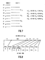
- the derivation of the chrominance signals is shown in Figure 7.
- First the 1050 2:1 source is converted to a 525 1:1 image, which implies no change in the data capacity. This conversion is accomplished using the same vertical filter as is used for luminance -- (1/4) : (3/4) for odd fields and (3/4) : (1/4) for even fields. This allows for compatibility with 525 1:1 and 525 2:1.
- the vertical processing shown in Figure 7 should be applied to the transmitted signals.
- the example in the figure is for field one lines of V.
- the interpolating filter requires two adjacent transmitted lines of a particular component, with successive weights of 15:1, 11:5, 7:9, and 3:13. This process repeats every four source lines.
- the fundamental format of transmission for the HDMAC-1050 system is comparable to transmission of signals in the HDMAC-60 system.
- the signal components and the corresponding "superline" timing budget are depicted.
- Y3 wideband luminance
- Y1 narrowband luminance
- LS2 and LS4 line subtraction signals from luminance
- U1 color difference for source line 1
- V3 color difference for line 3
- C1 clamp interval
- DSS digital synchronization and compact disk quality stereo sound
- chrominance signal bandwidths for each color difference signal may alternate on a particular field to field sequence as with HDMAC-60, but this feature is not a mandatory requirement. It is a feature that better matches the two-dimensional chrominance spectrum to the "diamond" response of the human visual system.
- the original 1050 2:1 source lines are vertically filtered in block 10 by a vertical FIR filter with coefficients (3/4) : (1/4) that alternate from field to field as previously described.
- the output of this vertical filter is the 525 1:1 signal.
- narrowband luminance line Y1 is formed.
- the original source wideband lines are 4:1 vertically decimated by block 30, and one of four lines are presented to the horizontal highpass filter block 40.
- This filter passes horizontal frequencies above 9.5 MHz and passes them to the vertical filter block 50, which is a FIR vertical filter device, which limits the vertical energy to help suppress aliasing after 1050 2:1 reconstruction at the decoder, as previously suggested.
- Wideband line Y3 is achieved by adding the Y1 narrowband component to the output of the vertical filter, using adder block 60.
- the line subtraction signal previously described is generated by FIR filter block 100 in Figure 9.
- the coefficients for the filter alternate from field to field from 1 : -1 to -1 : 1, as previously described.
- All encoder processing can now be performed on the HDMAC-1050 components derived above using the HDMAC-60 formatting hardware, with Y1, Y3, LS2, and LS4 substituted for components Y1, Y3, LD2, and LD4 in HDMAC-60.
- the chrominance signals derived in Figure 9 must be applied, which requires another vertical filter block 10 of Figure 11, and a decimator. Equalizing delays must also be provided that are tailored to the processing in the HDMAC-1050 video paths.
- the fundamental HDMAC-60 formatting hardware will suffice, but the video reconstruction must be performed for luminance according to the equations in Appendix 2 for luminance and Figure 7 for chrominance.
- Vertical interpolation of the high frequency luminance signal may be treated in the same manner for HDMAC-1050 and HDMAC-60 because a 1:4 interpolation is required in both systems.
- FIG. 10 a comparison of the two-dimensional luminance spectras expected from both HDMAC formats is shown in Figure 10.
- a first interlacing contribution region I1 above 480 TVL in HDMAC-1050 is shown at 30 Hz, due to the nature of interlace.
- HDMAC-1050 further provides a second 30 Hz interlacing contribution region I2 and a line subtraction contribution region LS which correspond to an interlacing contribution region I and a line differential contribution region LD in HDMAC-60.
- HDMAC-60 allows for the potential for more diagonal energy with less threat of heavy aliasing
- the HDMAC-1050 signal requires more filtering of this region to prevent severe aliasing due to the slow temporal update rate.
- Figure 10 indicates a field update rate of 7.5 Hz for HDMAC-1050, as described in the vertical decimation sequence embodiment illustrated by Fig. 8. It is to be noted however that the instant invention is not limited to the use of this particular decimation sequence and other vertical filtering techniques in conjunction with other decimation sequences can be used which will allow for higher field update rates, for example 15 Hz.
Landscapes
- Engineering & Computer Science (AREA)
- Multimedia (AREA)
- Signal Processing (AREA)
- Television Systems (AREA)
- Color Television Systems (AREA)
Applications Claiming Priority (2)
| Application Number | Priority Date | Filing Date | Title |
|---|---|---|---|
| US07/271,136 US4992853A (en) | 1988-11-14 | 1988-11-14 | System for transmission and reception of a high definition time multiplexed analog component (HDMAC) television signal having an interlaced input/output format |
| US271136 | 1994-07-06 |
Publications (2)
| Publication Number | Publication Date |
|---|---|
| EP0369523A2 true EP0369523A2 (fr) | 1990-05-23 |
| EP0369523A3 EP0369523A3 (fr) | 1991-07-17 |
Family
ID=23034346
Family Applications (1)
| Application Number | Title | Priority Date | Filing Date |
|---|---|---|---|
| EP19890202819 Withdrawn EP0369523A3 (fr) | 1988-11-14 | 1989-11-08 | Système de télévision haute définition à composantes analogiques multiplexées temporellement (HDMAC) |
Country Status (4)
| Country | Link |
|---|---|
| US (1) | US4992853A (fr) |
| EP (1) | EP0369523A3 (fr) |
| JP (1) | JPH02192377A (fr) |
| CA (1) | CA2002818A1 (fr) |
Cited By (2)
| Publication number | Priority date | Publication date | Assignee | Title |
|---|---|---|---|---|
| WO2011035406A1 (fr) * | 2009-09-24 | 2011-03-31 | Sensio Technologies Inc. | Procédé et système de transmission et de traitement de signaux vidéo numériques de haute définition |
| CN103442371A (zh) * | 2013-07-04 | 2013-12-11 | 无锡盟欣智能科技有限公司 | 一种无线网络扩展装置 |
Families Citing this family (3)
| Publication number | Priority date | Publication date | Assignee | Title |
|---|---|---|---|---|
| US5214501A (en) * | 1988-10-03 | 1993-05-25 | North American Philips Corporation | Method and apparatus for the transmission and reception of a multicarrier high definition television signal |
| JP2977104B2 (ja) * | 1991-07-26 | 1999-11-10 | ソニー株式会社 | 動画像データエンコード方法および装置、並びに動画像データデコード方法および装置 |
| US6724948B1 (en) * | 1999-12-27 | 2004-04-20 | Intel Corporation | Scaling images for display |
Family Cites Families (7)
| Publication number | Priority date | Publication date | Assignee | Title |
|---|---|---|---|---|
| JPS58225786A (ja) * | 1982-06-25 | 1983-12-27 | Nippon Hoso Kyokai <Nhk> | 高品位テレビジョン伝送方法 |
| JPS59219083A (ja) * | 1983-05-27 | 1984-12-10 | Nippon Hoso Kyokai <Nhk> | テレビジヨン画像信号伝送方式 |
| NL192488C (nl) * | 1983-12-05 | 1997-08-04 | Philips Electronics Nv | Informatiegever en informatie-ontvanger met overdracht van extra informatie behorend bij de televisie-rasteraftastinrichting. |
| JPS60134692A (ja) * | 1983-12-23 | 1985-07-17 | Hitachi Ltd | テレビジヨン装置 |
| US4589011A (en) * | 1984-01-16 | 1986-05-13 | At&T Bell Laboratories | Single sideband modulated chrominance information for compatible high-definition television |
| JPS60158785A (ja) * | 1984-01-30 | 1985-08-20 | Nippon Hoso Kyokai <Nhk> | 画像信号帯域圧縮伝送方式 |
| US4908697A (en) * | 1987-07-24 | 1990-03-13 | North American Philips Corporation | Two-line mac high definition television system |
-
1988
- 1988-11-14 US US07/271,136 patent/US4992853A/en not_active Expired - Fee Related
-
1989
- 1989-11-08 EP EP19890202819 patent/EP0369523A3/fr not_active Withdrawn
- 1989-11-13 JP JP1294756A patent/JPH02192377A/ja active Pending
- 1989-11-14 CA CA002002818A patent/CA2002818A1/fr not_active Abandoned
Cited By (2)
| Publication number | Priority date | Publication date | Assignee | Title |
|---|---|---|---|---|
| WO2011035406A1 (fr) * | 2009-09-24 | 2011-03-31 | Sensio Technologies Inc. | Procédé et système de transmission et de traitement de signaux vidéo numériques de haute définition |
| CN103442371A (zh) * | 2013-07-04 | 2013-12-11 | 无锡盟欣智能科技有限公司 | 一种无线网络扩展装置 |
Also Published As
| Publication number | Publication date |
|---|---|
| JPH02192377A (ja) | 1990-07-30 |
| US4992853A (en) | 1991-02-12 |
| EP0369523A3 (fr) | 1991-07-17 |
| CA2002818A1 (fr) | 1990-05-14 |
Similar Documents
| Publication | Publication Date | Title |
|---|---|---|
| US4908697A (en) | Two-line mac high definition television system | |
| EP0263112B1 (fr) | Traitement de signaux video en vue d'une reduction de la largeur de bande | |
| US4794447A (en) | Method and apparatus for transmitting and receiving a high definition NTSC compatible television signal over a single DBS channel in time division multiplex form | |
| US4942466A (en) | Bandwidth compression for television signals | |
| US5055927A (en) | Dual channel video signal transmission system | |
| CN1078797C (zh) | 提供可定标的压缩视频信号的方法和设备 | |
| US4967272A (en) | Bandwidth reduction and multiplexing of multiple component TV signals | |
| US4989091A (en) | Scan converter for a high definition television system | |
| JPH01200882A (ja) | 信号処理方法及び該信号受信装置 | |
| US5159453A (en) | Video processing method and apparatus | |
| EP0376978B1 (fr) | Procede et appareil ameliorant la definition verticale d'un signal de television transmis | |
| US4621287A (en) | Time-multiplexing of an interleaved spectrum of a television signal | |
| EP0386805A2 (fr) | Traitement de signaux de télévision à haute définition | |
| US4974064A (en) | Apparatus for encoding television signals of different formats for transmission and decoding upon reception | |
| EP0369523A2 (fr) | Système de télévision haute définition à composantes analogiques multiplexées temporellement (HDMAC) | |
| US5043805A (en) | TV signal transmission systems and methods | |
| JPS60229491A (ja) | 画像処理方法及び装置 | |
| US5113242A (en) | Two-line MAC high definition television system | |
| JPH04330884A (ja) | 多重信号受信装置 | |
| US5111287A (en) | TV signal transmission systems and methods | |
| EP0163512B1 (fr) | Traitement spatio-temporel à imbrication de fréquence d'un signal de télévision | |
| GB2191062A (en) | Transmitting television signals | |
| US4999701A (en) | High definition NTSC compatible television system with increased horizontal bandwidth and reduced color artifacts | |
| US5055915A (en) | Method and apparatus for the transmission and reception of two conventional television signals using a two-line MAC format | |
| US5278648A (en) | Mixed field time-multiplexed video transmission system and method |
Legal Events
| Date | Code | Title | Description |
|---|---|---|---|
| PUAI | Public reference made under article 153(3) epc to a published international application that has entered the european phase |
Free format text: ORIGINAL CODE: 0009012 |
|
| AK | Designated contracting states |
Kind code of ref document: A2 Designated state(s): DE FR GB |
|
| PUAL | Search report despatched |
Free format text: ORIGINAL CODE: 0009013 |
|
| AK | Designated contracting states |
Kind code of ref document: A3 Designated state(s): DE FR GB |
|
| STAA | Information on the status of an ep patent application or granted ep patent |
Free format text: STATUS: THE APPLICATION IS DEEMED TO BE WITHDRAWN |
|
| 18D | Application deemed to be withdrawn |
Effective date: 19920118 |