EP0369541B1 - Modulated gas radiator - Google Patents
Modulated gas radiator Download PDFInfo
- Publication number
- EP0369541B1 EP0369541B1 EP89202874A EP89202874A EP0369541B1 EP 0369541 B1 EP0369541 B1 EP 0369541B1 EP 89202874 A EP89202874 A EP 89202874A EP 89202874 A EP89202874 A EP 89202874A EP 0369541 B1 EP0369541 B1 EP 0369541B1
- Authority
- EP
- European Patent Office
- Prior art keywords
- air
- chamber
- gas
- burner
- outlet
- Prior art date
- Legal status (The legal status is an assumption and is not a legal conclusion. Google has not performed a legal analysis and makes no representation as to the accuracy of the status listed.)
- Expired - Lifetime
Links
Images

Classifications
-
- F—MECHANICAL ENGINEERING; LIGHTING; HEATING; WEAPONS; BLASTING
- F23—COMBUSTION APPARATUS; COMBUSTION PROCESSES
- F23D—BURNERS
- F23D14/00—Burners for combustion of a gas, e.g. of a gas stored under pressure as a liquid
- F23D14/34—Burners specially adapted for use with means for pressurising the gaseous fuel or the combustion air
-
- F—MECHANICAL ENGINEERING; LIGHTING; HEATING; WEAPONS; BLASTING
- F23—COMBUSTION APPARATUS; COMBUSTION PROCESSES
- F23D—BURNERS
- F23D14/00—Burners for combustion of a gas, e.g. of a gas stored under pressure as a liquid
- F23D14/46—Details
- F23D14/62—Mixing devices; Mixing tubes
- F23D14/64—Mixing devices; Mixing tubes with injectors
-
- F—MECHANICAL ENGINEERING; LIGHTING; HEATING; WEAPONS; BLASTING
- F23—COMBUSTION APPARATUS; COMBUSTION PROCESSES
- F23D—BURNERS
- F23D14/00—Burners for combustion of a gas, e.g. of a gas stored under pressure as a liquid
- F23D14/46—Details
- F23D14/68—Treating the combustion air or gas, e.g. by filtering, or moistening
-
- F—MECHANICAL ENGINEERING; LIGHTING; HEATING; WEAPONS; BLASTING
- F23—COMBUSTION APPARATUS; COMBUSTION PROCESSES
- F23N—REGULATING OR CONTROLLING COMBUSTION
- F23N1/00—Regulating fuel supply
- F23N1/02—Regulating fuel supply conjointly with air supply
Definitions
- This invention relates to a gas-fired heating apparatus, in particular a heating apparatus of the type having radiant bodies to be heated by gas flames, and in which fuel gas and combustion air are supplied under pressure to at least one burner nozzle in a proportion ensuring complete combustion, and further comprising in association with said at least one burner, an air chamber to which the combustion air is supplied, said chamber having an outlet terminating in the ambient space, a venturi extending from said chamber into the burner, and a gas supply nozzle disposed within the chamber coaxially in front of the venturi throat, as disclosed in JP-A-59 202318 (MATSUSHITA DENKI SANGYO K.K.).
- An advantage of such an apparatus is that no polluted air is sucked in from the ambient space, which may give rise to fouling of burners.
- the air supply and gas supply are controlled in dependence upon measurements of the air pressure within the air chamber and the gas pressure within the gas supply conduit to the nozzle.
- adjustment is effected with throttle means in the gas supply path and in the outlet to the outside air, the arrangement being such that the adjusted ratio has a constant value.
- means are provided for supplying a constant rate of air to the chamber in a quantity slightly larger than needed for complete combustion when the burner is operated at maximum capacity, and further by said outlet being of sufficient dimensions to offer no essential resistance to air flowing out into the ambient space.
- the apparatus according to the invention operates as follows: Owing to the combined effect of the effluent gas and the venturi, combustion air is sucked in at all times in a quantity sufficient for a complete combustion of the gas supplied. The air required is withdrawn from the chamber to which, however, the air is supplied in a slight excess. The excess can escape through the outlet.
- the advantages of the prior apparatus namely, clean air is supplied to the burner and there is a constant gas/air ratio
- the disadvantage of the prior apparatus namely, complex adjustment in the case of gas pressure fluctuations
- the invention owing to the relatively large outlet of the air chamber to the outside air, there is effected an automatic adaptation of the supply of air of combustion to the instantaneous gas rate, so that even when the gas pressure is greatly reduced, and accordingly the burner requires a much smaller quantity of air, no essential overpressure is created within the chamber, not even temporarily, because the outlet offers no essential resistance to air flowing out into the ambient atmosphere.
- the outlet ensures that through this opening, as a result of the effect of the venturi, air can be drawn into the chamber from the ambient atmosphere, so that even in the case of such calamities, the burner does not fail.
- the outlet is equipped with a relatively coarse (gauze) filter.
- this filter is not fouled, because it only needs to pass clean excess air of combustion.
- the filter retains dirt from the ambient atmosphere.
- an air pump arranged to deliver air under pressure to said chamber through an air conduit, and a pressure reducing means at the junction between said air conduit and said chamber.
- a structurally simple pressure reducing means comprises an adjustable passage and a widening transition member to the chamber.
- the apparatus comprises an air conduit 1 and a gas conduit 2. Clean air is pumped into the air conduit by an air pump, which air is drawn in through an air filter 4, so that a substantially constant overpressure prevails within the air conduit.
- Branch lines for example, in the form of flexible tubes 5, extend from the air conduit 1 to heat radiators 6 distributed over the space to be heated.
- tube 5 is connected to radiator 6 through a controllable or calibrated passage 7, a reducing member 8, a chamber 9, and a venturi 10.
- Chamber 9 is provided with an outlet 11 with a gauze filter 12.
- the gas conduit 2 is fed through a pressure control valve 14 operated by a motor 13 and controlled by a regulator 15, which may be equipped with a temperature sensor. Branching from gas conduit 2 are gas supply lines 17, equipped with valves 16, to the respective chambers 9. Each gas supply line 17 terminates coaxially with the venturi 10 in a nozzle 18 located in front of throat 19 of the venturi.
- the venturi terminates in a burner which is in the form shown is an incandescent body 20 functioning as a heat radiator.
- gas is blown at a variable pressure from nozzle 18 into the throat 19 of venturi 10.
- air is at all times drawn from chamber 9 in a quantity sufficient for a complete combustion of the gas supplied.
- Pump 3 supplies so much air that in each chamber 9 the supply of air is at all times slightly greater than needed for complete combustion of the gas supplied when the burner is operated under full-load conditions. The excess of air escapes through the outlet 11 into the ambient atmosphere.
- the outlet is dimensioned so that it offers no significant resistance to escaping air.
- the apparatus according to the invention offers additional safeguard against calamities, for example, failure of the air pump 3 and/or complete clogging of the air filter 4. In such cases, insufficient air, or none at all, is supplied through tube 5. Nevertheless, sufficient air can be drawn in through outlet 11. The gauze filter 12 then prevents the ingress of dirt. In order that, during normal operation, filter 12 should offer minimal resistance to effluent excess air, a relatively coarse gauze is selected for the filter 12.
- the apparatus according to the invention enlarges the applicability of gas-fired heat radiators, especially in polluted environments, without complex and expensive constructions being required.
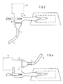
- Figs. 3 and 4 illustrate other embodiments of chamber 9 in which the positions of air passage 7 and outlet 11 are diametrically opposite.
Landscapes
- Engineering & Computer Science (AREA)
- Chemical & Material Sciences (AREA)
- Combustion & Propulsion (AREA)
- Mechanical Engineering (AREA)
- General Engineering & Computer Science (AREA)
- Regulation And Control Of Combustion (AREA)
- Pre-Mixing And Non-Premixing Gas Burner (AREA)
- Gas Burners (AREA)
Applications Claiming Priority (2)
| Application Number | Priority Date | Filing Date | Title |
|---|---|---|---|
| NL8802791 | 1988-11-14 | ||
| NL8802791A NL8802791A (nl) | 1988-11-14 | 1988-11-14 | Modulerend geregelde gasstraler. |
Publications (2)
| Publication Number | Publication Date |
|---|---|
| EP0369541A1 EP0369541A1 (en) | 1990-05-23 |
| EP0369541B1 true EP0369541B1 (en) | 1993-10-27 |
Family
ID=19853215
Family Applications (1)
| Application Number | Title | Priority Date | Filing Date |
|---|---|---|---|
| EP89202874A Expired - Lifetime EP0369541B1 (en) | 1988-11-14 | 1989-11-13 | Modulated gas radiator |
Country Status (5)
| Country | Link |
|---|---|
| US (1) | US5076781A (es) |
| EP (1) | EP0369541B1 (es) |
| DE (1) | DE68910277T2 (es) |
| ES (1) | ES2045393T3 (es) |
| NL (1) | NL8802791A (es) |
Families Citing this family (10)
| Publication number | Priority date | Publication date | Assignee | Title |
|---|---|---|---|---|
| US5353986A (en) * | 1993-06-15 | 1994-10-11 | Detroit Radiant Products Company | Demand radiant heating system |
| US5642724A (en) * | 1993-11-29 | 1997-07-01 | Teledyne Industries, Inc. | Fluid mixing systems and gas-fired water heater |
| US5431557A (en) * | 1993-12-16 | 1995-07-11 | Teledyne Industries, Inc. | Low NOX gas combustion systems |
| US5516282A (en) * | 1995-01-03 | 1996-05-14 | Unique Marketing 2000 Inc. | Burner tube and space heater employing the tube |
| FR2826434B1 (fr) * | 2001-06-26 | 2004-10-22 | 4E | Rampe de chauffage, notamment pour batiments d'elevage |
| US6786422B1 (en) | 2001-10-30 | 2004-09-07 | Detroit Radiant Products Co. | Infrared heating assembly |
| US6971871B2 (en) * | 2004-02-06 | 2005-12-06 | Solaronics, Inc. | Variable low intensity infrared heater |
| US8656904B2 (en) * | 2009-09-25 | 2014-02-25 | Detroit Radiant Products Co. | Radiant heater |
| EP2789915A1 (en) * | 2013-04-10 | 2014-10-15 | Alstom Technology Ltd | Method for operating a combustion chamber and combustion chamber |
| CN120947029B (zh) * | 2025-09-12 | 2026-04-14 | 醴陵陶润实业发展有限公司 | 基于不同燃料混合的燃烧控制方法 |
Family Cites Families (4)
| Publication number | Priority date | Publication date | Assignee | Title |
|---|---|---|---|---|
| DE1113532B (de) * | 1957-11-15 | 1961-09-07 | Licentia Gmbh | Strahlapparat, der der Herstellung eines Brenngemisches dient |
| JPS58161107A (ja) * | 1982-03-19 | 1983-09-24 | Canon Inc | 磁気記録装置 |
| JPS59202318A (ja) * | 1983-04-28 | 1984-11-16 | Matsushita Electric Ind Co Ltd | ガス燃焼制御装置 |
| FR2560359B3 (fr) * | 1984-02-23 | 1987-04-10 | Laurent Francois | Perfectionnements a un dispositif de chauffage a bruleur a gaz et tube radiant |
-
1988
- 1988-11-14 NL NL8802791A patent/NL8802791A/nl not_active Application Discontinuation
-
1989
- 1989-11-13 EP EP89202874A patent/EP0369541B1/en not_active Expired - Lifetime
- 1989-11-13 DE DE89202874T patent/DE68910277T2/de not_active Expired - Fee Related
- 1989-11-13 ES ES89202874T patent/ES2045393T3/es not_active Expired - Lifetime
- 1989-11-14 US US07/436,213 patent/US5076781A/en not_active Expired - Fee Related
Also Published As
| Publication number | Publication date |
|---|---|
| NL8802791A (nl) | 1990-06-01 |
| DE68910277D1 (de) | 1993-12-02 |
| EP0369541A1 (en) | 1990-05-23 |
| ES2045393T3 (es) | 1994-01-16 |
| US5076781A (en) | 1991-12-31 |
| DE68910277T2 (de) | 1994-04-28 |
Similar Documents
| Publication | Publication Date | Title |
|---|---|---|
| US8061347B2 (en) | Dual fuel vent free gas heater | |
| US5076781A (en) | Modulated gas radiator | |
| US5860411A (en) | Modulating gas valve furnace control method | |
| USRE46308E1 (en) | Dual fuel heater | |
| US4436506A (en) | Control system for a gas heated water or air heater | |
| US3843310A (en) | Combustion control device | |
| CA2229129C (en) | A differential pressure modulated gas valve for single stage combustion control | |
| US4189295A (en) | Control for heating apparatus | |
| US4573912A (en) | Space heater | |
| EP0279771B1 (de) | Verfahren zum Regeln des Verbrennungsluftdurchsatzes für eine brennstoffbeheizte Wärmequelle | |
| KR930006168B1 (ko) | 연소기의 제어장치 | |
| EP0320072A2 (en) | Heating appliance | |
| CA1147225A (en) | Combustion device | |
| KR930006170B1 (ko) | 연소기의 제어장치 | |
| EP0509155A1 (en) | Radiant heating systems | |
| KR910002734B1 (ko) | 연소제어장치 | |
| JPH0268449A (ja) | バイパスミキシング式給湯器 | |
| KR940004171B1 (ko) | 바이패스 믹싱식 급탕기 | |
| JP3215557B2 (ja) | 燃焼装置 | |
| GB2059568A (en) | Burner controls | |
| CA2003021A1 (en) | Devices for controlling and regulating the gas supply to the burner of a boiler or similar | |
| JPS6325252B2 (es) | ||
| JP3570227B2 (ja) | 燃焼装置 | |
| JP2642272B2 (ja) | 強制送風式燃焼機器 | |
| JPH02161210A (ja) | 燃焼装置 |
Legal Events
| Date | Code | Title | Description |
|---|---|---|---|
| PUAI | Public reference made under article 153(3) epc to a published international application that has entered the european phase |
Free format text: ORIGINAL CODE: 0009012 |
|
| AK | Designated contracting states |
Kind code of ref document: A1 Designated state(s): BE DE ES FR IT NL |
|
| 17P | Request for examination filed |
Effective date: 19901121 |
|
| 17Q | First examination report despatched |
Effective date: 19920422 |
|
| GRAA | (expected) grant |
Free format text: ORIGINAL CODE: 0009210 |
|
| AK | Designated contracting states |
Kind code of ref document: B1 Designated state(s): BE DE ES FR IT NL |
|
| ITF | It: translation for a ep patent filed | ||
| REF | Corresponds to: |
Ref document number: 68910277 Country of ref document: DE Date of ref document: 19931202 |
|
| ET | Fr: translation filed | ||
| REG | Reference to a national code |
Ref country code: ES Ref legal event code: FG2A Ref document number: 2045393 Country of ref document: ES Kind code of ref document: T3 |
|
| PLBE | No opposition filed within time limit |
Free format text: ORIGINAL CODE: 0009261 |
|
| STAA | Information on the status of an ep patent application or granted ep patent |
Free format text: STATUS: NO OPPOSITION FILED WITHIN TIME LIMIT |
|
| 26N | No opposition filed | ||
| PGFP | Annual fee paid to national office [announced via postgrant information from national office to epo] |
Ref country code: ES Payment date: 19981113 Year of fee payment: 10 |
|
| PGFP | Annual fee paid to national office [announced via postgrant information from national office to epo] |
Ref country code: FR Payment date: 19981126 Year of fee payment: 10 |
|
| PGFP | Annual fee paid to national office [announced via postgrant information from national office to epo] |
Ref country code: DE Payment date: 19981127 Year of fee payment: 10 |
|
| PGFP | Annual fee paid to national office [announced via postgrant information from national office to epo] |
Ref country code: NL Payment date: 19981130 Year of fee payment: 10 |
|
| PGFP | Annual fee paid to national office [announced via postgrant information from national office to epo] |
Ref country code: BE Payment date: 19981210 Year of fee payment: 10 |
|
| PG25 | Lapsed in a contracting state [announced via postgrant information from national office to epo] |
Ref country code: ES Free format text: LAPSE BECAUSE OF NON-PAYMENT OF DUE FEES Effective date: 19991114 |
|
| PG25 | Lapsed in a contracting state [announced via postgrant information from national office to epo] |
Ref country code: BE Free format text: LAPSE BECAUSE OF NON-PAYMENT OF DUE FEES Effective date: 19991130 |
|
| BERE | Be: lapsed |
Owner name: FANCOM B.V. Effective date: 19991130 |
|
| PG25 | Lapsed in a contracting state [announced via postgrant information from national office to epo] |
Ref country code: NL Free format text: LAPSE BECAUSE OF NON-PAYMENT OF DUE FEES Effective date: 20000601 |
|
| PG25 | Lapsed in a contracting state [announced via postgrant information from national office to epo] |
Ref country code: FR Free format text: LAPSE BECAUSE OF NON-PAYMENT OF DUE FEES Effective date: 20000731 |
|
| NLV4 | Nl: lapsed or anulled due to non-payment of the annual fee |
Effective date: 20000601 |
|
| PG25 | Lapsed in a contracting state [announced via postgrant information from national office to epo] |
Ref country code: DE Free format text: LAPSE BECAUSE OF NON-PAYMENT OF DUE FEES Effective date: 20000901 |
|
| REG | Reference to a national code |
Ref country code: FR Ref legal event code: ST |
|
| REG | Reference to a national code |
Ref country code: ES Ref legal event code: FD2A Effective date: 20001214 |
|
| PG25 | Lapsed in a contracting state [announced via postgrant information from national office to epo] |
Ref country code: IT Free format text: LAPSE BECAUSE OF NON-PAYMENT OF DUE FEES Effective date: 20051113 |