EP0369680B1 - Fensterheber mit Rückstelleinrichtung - Google Patents
Fensterheber mit Rückstelleinrichtung Download PDFInfo
- Publication number
- EP0369680B1 EP0369680B1 EP89311607A EP89311607A EP0369680B1 EP 0369680 B1 EP0369680 B1 EP 0369680B1 EP 89311607 A EP89311607 A EP 89311607A EP 89311607 A EP89311607 A EP 89311607A EP 0369680 B1 EP0369680 B1 EP 0369680B1
- Authority
- EP
- European Patent Office
- Prior art keywords
- glass
- members
- drive
- upright
- window
- Prior art date
- Legal status (The legal status is an assumption and is not a legal conclusion. Google has not performed a legal analysis and makes no representation as to the accuracy of the status listed.)
- Expired - Lifetime
Links
Images


Classifications
-
- B—PERFORMING OPERATIONS; TRANSPORTING
- B60—VEHICLES IN GENERAL
- B60J—WINDOWS, WINDSCREENS, NON-FIXED ROOFS, DOORS, OR SIMILAR DEVICES FOR VEHICLES; REMOVABLE EXTERNAL PROTECTIVE COVERINGS SPECIALLY ADAPTED FOR VEHICLES
- B60J1/00—Windows; Windscreens; Accessories therefor
- B60J1/08—Windows; Windscreens; Accessories therefor arranged at vehicle sides
- B60J1/12—Windows; Windscreens; Accessories therefor arranged at vehicle sides adjustable
- B60J1/16—Windows; Windscreens; Accessories therefor arranged at vehicle sides adjustable slidable
- B60J1/17—Windows; Windscreens; Accessories therefor arranged at vehicle sides adjustable slidable vertically
-
- B—PERFORMING OPERATIONS; TRANSPORTING
- B60—VEHICLES IN GENERAL
- B60J—WINDOWS, WINDSCREENS, NON-FIXED ROOFS, DOORS, OR SIMILAR DEVICES FOR VEHICLES; REMOVABLE EXTERNAL PROTECTIVE COVERINGS SPECIALLY ADAPTED FOR VEHICLES
- B60J5/00—Doors
- B60J5/04—Doors arranged at the vehicle sides
- B60J5/0412—Lower door structure
- B60J5/0416—Assembly panels to be installed in doors as a module with components, e.g. lock or window lifter, attached thereto
-
- E—FIXED CONSTRUCTIONS
- E05—LOCKS; KEYS; WINDOW OR DOOR FITTINGS; SAFES
- E05F—DEVICES FOR MOVING WINGS INTO OPEN OR CLOSED POSITION; CHECKS FOR WINGS; WING FITTINGS NOT OTHERWISE PROVIDED FOR, CONCERNED WITH THE FUNCTIONING OF THE WING
- E05F11/00—Man-operated mechanisms for operating wings, including those which also operate the fastening
- E05F11/38—Man-operated mechanisms for operating wings, including those which also operate the fastening for sliding windows, e.g. vehicle windows, to be opened or closed by vertical movement
- E05F11/52—Man-operated mechanisms for operating wings, including those which also operate the fastening for sliding windows, e.g. vehicle windows, to be opened or closed by vertical movement combined with means for producing an additional movement, e.g. a horizontal or a rotary movement
- E05F11/525—Man-operated mechanisms for operating wings, including those which also operate the fastening for sliding windows, e.g. vehicle windows, to be opened or closed by vertical movement combined with means for producing an additional movement, e.g. a horizontal or a rotary movement for vehicle windows
-
- E—FIXED CONSTRUCTIONS
- E05—LOCKS; KEYS; WINDOW OR DOOR FITTINGS; SAFES
- E05F—DEVICES FOR MOVING WINGS INTO OPEN OR CLOSED POSITION; CHECKS FOR WINGS; WING FITTINGS NOT OTHERWISE PROVIDED FOR, CONCERNED WITH THE FUNCTIONING OF THE WING
- E05F15/00—Power-operated mechanisms for wings
- E05F15/60—Power-operated mechanisms for wings using electrical actuators
- E05F15/603—Power-operated mechanisms for wings using electrical actuators using rotary electromotors
- E05F15/665—Power-operated mechanisms for wings using electrical actuators using rotary electromotors for vertically-sliding wings
- E05F15/689—Power-operated mechanisms for wings using electrical actuators using rotary electromotors for vertically-sliding wings specially adapted for vehicle windows
-
- E—FIXED CONSTRUCTIONS
- E05—LOCKS; KEYS; WINDOW OR DOOR FITTINGS; SAFES
- E05Y—INDEXING SCHEME ASSOCIATED WITH SUBCLASSES E05D AND E05F, RELATING TO CONSTRUCTION ELEMENTS, ELECTRIC CONTROL, POWER SUPPLY, POWER SIGNAL OR TRANSMISSION, USER INTERFACES, MOUNTING OR COUPLING, DETAILS, ACCESSORIES, AUXILIARY OPERATIONS NOT OTHERWISE PROVIDED FOR, APPLICATION THEREOF
- E05Y2900/00—Application of doors, windows, wings or fittings thereof
- E05Y2900/50—Application of doors, windows, wings or fittings thereof for vehicles
- E05Y2900/53—Type of wing
- E05Y2900/55—Windows
Definitions
- This invention relates generally to a window regulator mechanism for a motor vehicle and more particularly to a dual drive window regulator mechanism which includes a kick-out feature to move the lower edge of the window glass outward as the glass reaches the raised position closing the window opening.
- window glass is flush with the vehicle exterior along all four sides of the glass.
- vehicle side door windows have been constructed with window glass that slides in a guide channel extending from a window storage cavity beneath the window opening upward along the periphery of the window opening. When the glass is in the raised position closing the window opening, the exterior surface of the glass is recessed relative to the exterior surface of the vehicle door.
- the window opening and glass guidance system with four-side flush glass is designed such that as the glass is raised to the upper position, the upper edge of the glass contacts and seals against the upper edge of the window opening flush with the vehicle exterior along the upper edge of the window opening.
- the difficulty is with positioning of the lower edge of the glass flush to the vehicle exterior.
- the door assembly In order to lower the window into a storage cavity beneath the window opening, it is necessary for the door assembly to have an opening along the sill at the bottom edge of the window opening to allow the glass to move downward into the storage cavity.
- This opening into the storage cavity by necessity is inboard of the outer surface of the door.
- GB-A-1 468 774 (or FR-A-2 279 581) discloses a window regulator mechanism in accordance with the prior art portion of claim 1.
- guide channels are provided at the top and bottom of the window space bodily laterally to displace the top and bottom of the glass window to fit flush into its aperture, such movement being accompanied by simultaneous lateral movement of the upper part of the lifting mechanism.
- the present invention provides a simple glass guidance system having a window regulator mechanism which incorporates the glass guidance system into the regulator system thereby eliminating the need for separate glass guide channels. It achieves this by appreciating the possibility of simply rotating the glass about its upper edge to cause flush fitting of its lower edge to the aperture, the drive for this rotation being obtainable from the same drive as causes lifting of the glass to its closed position, but without need to displace the lifting drive itself and without a complicated rotary pusher cam lever as used in GB-A-1 468 774.
- the present invention as defined in claim 1 provides a window regulator mechanism having a kick-out mechanism which does not require use of a separate glass guide system and which operates in a very simple and positive manner, using guide means to move the bottom of the window laterally as the glass is moved into the upper closed position.
- the window regulator mechanism of this invention includes a dual drive system which drives the window glass at two points, one at the forward edge of the glass and the other at the rearward edge of the glass.
- the glass in the later illustrated embodiment is driven by translating racks contained within stationary tracks.
- the regulator includes two racks, one connected to each drive point on the glass.
- Each track has a longitudinal slot along one side providing access to evenly spaced transverse teeth in the rack.
- the teeth of a drive pinion extend through the slots in the track and engage the teeth of the rack.
- a mounting flange attached to the end of the rack in each track is used to connect the rack to the glass at the drive point.
- the attachment of the mounting flange to the glass includes a pair of sliding blocks.
- the mounting flange is attached to a lower dovetail sliding block which includes a dovetail shaped mortise along its upper surface.
- An upper dovetail block, having a corresponding dovetail tenon, is positioned above the lower block with the tenon engaged with the mortise.
- the mortise and tenon extend side-to-side relative to the vehicle door to allow the upper block to move outward as the glass is raised.
- a pin extending from the upper dovetail block engages a slotted cam as the glass approaches its upper position. The slotted cam urges the upper dovetail block outward moving the lower edge of the window glass flush with the vehicle exterior along the lower edge of the window opening.
- the slotted cam is replaced with an inclined wedge which engages the upper dovetail block and urges it outward as the glass approaches the raised position.
- a push rod extends inwardly from the glass through a rod guide attached to the mounting flange.
- a button is attached to the opposite end of the push rod by a ball and socket joint.
- the button has an annular groove around its periphery which engages a guide rail positioned generally parallel to the track.
- the upper end of the guide rail is inclined outward such that as the glass is raised, the button follows the incline in the guide rail and moves outward, thereby sliding the push rod through the rod guide, pushing the lower edge of the glass outward into a flush relationship with the door exterior surface.
- the dual drive window regulator mechanism of this invention is shown in Figure 1 assembled in a vehicle door assembly 10.
- the door assembly includes a door skin 12 having an outer sheet metal panel 14, the outer surface of which defines the exterior surface of the door.
- the door skin also includes a window frame 16 which defines a window opening 18.
- the door assembly 10 also includes a functional door cartridge 19 comprised of the window regulator mechanism 20, window glass 22 and cross member 24 being inserted into the door skin 12.
- a functional door cartridge 19 comprised of the window regulator mechanism 20, window glass 22 and cross member 24 being inserted into the door skin 12.
- the regulator mechanism of this invention is not limited to use in a vehicle door assembly constructed with a functional door cartridge but can be used in conventional vehicle door assemblies.
- the window regulator mechanism 20 includes a forward track 26 and a rearward track 28 which extend vertically at the forward and rearward edges 23 and 25 respectively, of the glass 22.
- the tracks 26 and 28 curve and extend horizontally along the lower edge of the door assembly.
- the two tracks 26 and 28 are hollow and define a generally rectangular shaped inner surface 29 shown in Figures 5 and 9.
- a slot 32 extends lengthwise of the tracks 26 and 28 also shown in Figures 5 and 9.
- the slot 32 in the two tracks 26 and 28 are facing rearward relative to the vehicle, to the right in Figure 1.
- the slots 32 in the two tracks face one another.
- a continuous rack member 34 preferably formed of a suitable flexible plastic material which can economically manufactured, is mounted in the tracks 26 and 28.
- the racks 34 are of generally rectangular shape in cross section corresponding to the rectangular shape of the inner surface 29 of the tracks 26 and 28.
- the racks 34 are formed with transverse evenly spaced grooves 36 which cooperate to form outwardly extending teeth 38 that are located facing the continuous slots 32 in the tracks.
- the grooves and teeth are shown in Figure 8.
- a drive pinion 40 is located at the center of the door assembly along the lower edge thereof and engages the racks 34 of both tracks 26 and 28 through the slots 32. As the drive pinion 40 is rotated by a motor 41, both racks 34 are simultaneously driven longitudinally through the tracks 26 and 28.
- Mounting flanges 42 are attached to the ends of the two racks 34 and extend outward through the slots 32, the function of which will be described in detail below. As the drive pinion 40 is rotated, simultaneously driving the two racks 34, the mounting flanges 42 are moved longitudinally relative to the two tracks 26 and 28.
- Figure 2 is a view looking toward the vehicle door assembly from the vehicle interior showing the kick-out structure at the top of the rearward track 28 with the glass 22 in the raised position.
- a lower dovetail slide block 44 is rotatably attached to the mounting flange 42 by a pin 46 extending through the lower dovetail block 44 and mounting flange 42.
- the lower dovetail block has a dovetail shaped groove or mortise 48 machined in its upper surface 50.
- An upper dovetail slide block 52 is positioned above lower dovetail block 44 and contains a dovetail shaped flaring tenon 54 for sliding within the mortise 48 of block 44.
- the mortise and tenon are directed longitudinally side-to-side relative to the vehicle door to allow the upper block to move outward as the glass is raised.
- a bracket 56 attaches the upper dovetail block 52 to a glass attaching bracket 58 extending along the lower edge of the glass 22. As the upper dovetail block 52 moves outward, the lower edge of the glass 22 moves outward from the phantom line position to the solid line position in Figure 3.
- the dovetail mortise and tenon are curved upwardly concaved as shown in Figure 3. This curve is necessary to provide for rotation of the glass 22 about an axis along the uppermost edge of the glass 22. Accordingly, the radius of curvature of the dovetail mortise and tenon is dictated by the size of the glass 22.
- the dovetail joint can be straight, as opposed to curved, and the attachment of bracket 56 to the upper dovetail block 52 can be pivoted to allow for the rotational movement of the glass.
- a cam 62 is provided to move the upper dovetail block outward as the window approaches the raised position.
- the cam 62 is constructed of a angle member having a mounting portion 64 attached to interior member 66 of the door assembly.
- a cam portion 68 extends outward from the mounting portion 64 and defines a slot 70.
- Slot 70 includes a generally vertical lower portion 72 which parallels the track 28 and an inclined upper portion 74 which is angled upward and outward relative to the vehicle from the vertical portion 72.
- a pin 76 extending from the side 78 of upper dovetail block 52 engages the slot 70 as the dovetail block 52 is raised. As the pin engages the inclined portion 74 of the slot, the pin follows the slot and moves the upper block 52 outward relative to the vehicle.
- Seal 88 defines the lower edge of the window opening 18 immediately above the sheet metal panel 14.
- a second pin extending from the lower dovetail block 44 and engaging only the vertical portion 72 of slot 70, can be provided to give greater stability to the positioning of the glass lower edge.
- Figure 4 is a view similar to Figure 3 in which the glass 22 has been lowered from the uppermost position shown in Figure 3 closing the window opening 18.
- the glass 22 is lowered by rotating the drive pinion 40 ( Figure 1) such that the racks 34 of tracks 26 and 28 are lowered, causing the mounting flanges 42 to move downward.
- the lower 44 and upper 52 dovetail blocks move downward resulting in lowering of the glass 22.
- the inclined slot 74 guides the pin 76 of the upper dovetail block inward. This results in moving the lower edge of the glass 22 inward as it begins to move downward.
- the lip 89 of seal 88 wipes the outer surface of the glass and seals against the glass to prevent water from entering the door assembly interior.
- the face 78 of the upper dovetail block 52 contains a channel 82 which engages the exterior of track 28 when the dovetail block is in a lowered position as shown in Figures 4 and 5.
- the purpose of the channel 82 is to prevent relative motion between the two dovetail blocks when the glass 22 is in a lowered position where the pin 76 no longer engages slot 70.
- the channel 82 thus provides side-to-side stability of the glass position thereby allowing accurate placement and alignment of the glass during travel.
- Separate guide channels, as used in previous window regulator mechanisms to position the glass, are no longer necessary. This results in a reduction in the number of components in the door assembly and the weight of the door assembly.
- Identical kick-out structure is provided at both glass drive attachment locations.
- Figure 6 shows a second embodiment of the sliding block dovetail kick-out mechanism shown in Figures 2-5.
- the cam 62 used to move the upper dovetail block outward as the window approaches the closed position has been replaced by a wedge 86 attached to the door assembly by screw 87.
- the wedge has an inclined surface 90 which, as viewed in Figure 6, is inclined outwardly and upwardly.
- the upper dovetail block 52 has a correspondingly inclined surface 92 which engages the surface 90 of wedge 86 as the dovetail block 52 is moved upward.
- the inclined surface forces the dovetail block to move outwardly thereby moving the glass 22 outward such that the glass lower edge is flush with the exterior surface of the door and rests upon seal 88.
- the surface 90 of the wedge and the engaging surface 92 of the upper dovetail block are also a curved concave upward. By curving these contact surfaces, surface contact is maintained as the upper block slides along the curved dovetail.
- a spring stop comprised of a coil spring 94, is attached to the inner surface of the sheet metal panel 14 and extends inwardly toward the upper dovetail block 52.
- the spring 94 is of sufficient length in the uncompressed condition that the glass mounting bracket 84 attached to the dovetail block 52 will engage the end of the spring 94 simultaneously with engagement of block 52 with wedge 86.
- the spring 94 thus ensures continuous engagement of the inclined surfaces 92 and 90 when the glass is in the raised position.
- the spring 94 moves the dovetail block 52 inward thereby moving the lower edge of glass 22 inward until the channel 82 in the upper dovetail block 52 engages the track 28 as described above with respect to Figures 4 and 5.
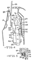
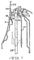
- a third embodiment of structure providing the kick-out feature is shown in Figures 7-9.
- the glass attaching bracket 102 is attached to the inner surface of glass 22 adjacent the lower glass edge. Bracket 102, like bracket 58, can be attached to the glass by bonding, a reaction injection molding process (RIM), or the like.
- the glass attaching bracket 102 has integrally formed thereon push rods 104 for attaching the glass 22 to the window regulator mechanism. Two push rods 104 are used, one at or near each edge 23 and 25 of the glass 22 at the two glass drive points. The end of push rod 104 extending away from the glass 22 forms a ball 106. Push rod 104 slides through a rod guide block 108 which in turn is attached to the mounting flange 42 by a pin 110 as shown in Figure 9.
- a circular button 112 having a central socket is mounted to the ball 106 of push rod 104 with a ball and socket joint which allows the button 112 to pivot about the ball 106.
- the outer periphery of the button 112 includes an annular groove 118.
- a flat guide rail 114 is positioned inwardly of the track 28 and is generally parallel to the track 28.
- the guide rail is a flat plate having a longitudinal slot 116.
- the button 112 is positioned within the slot 116 with the groove 118 engaging the edges of slot 116 in the guide rail.
- the upper end of the guide rail 114 is inclined outwardly at 115 as shown in Figure 7.
- the rod guide 108 also moves upward.
- the button 112 enters the inclined portion of the guide rail 114.
- the button 112 pivots around the ball 106 and moves outward sliding the push rod outward through the rod guide 108.
- the outward motion of the push rod moves the lower edge of the glass 22 outward such that it seats upon the seal 88.
- the button 112 follows the guide rail and moves inward thus pulling the lower edge of the glass inward off the seal 88 and into the storage cavity.
- the lower edge of the glass and rod guide are shown in phantom lines in Figure 7 in a lowered position.
- a glass kick-out mechanism is thus provided for use with a window regulator which provides both glass guidance and glass motion without the use of separate glass guide channels.
- the kick-out structure moves the lower edge of the glass outward to a position flush with the vehicle exterior.
- the same structure used to apply forces to raise and lower the glass is also used to move the lower edge of the glass outward as the glass approaches the upper position.
Landscapes
- Engineering & Computer Science (AREA)
- Mechanical Engineering (AREA)
- Window Of Vehicle (AREA)
- Power-Operated Mechanisms For Wings (AREA)
Claims (5)
- Fenstereinstellmechanismus (20) für eine Fahrzeugtüranordnung mit einer Außenfläche (14), einer im allgemeinen vertikalen Fensteröffnung (18) und einem Aufbewahrungshohlraum unter der Fensteröffnung, einem im allgemeinen vertikalen Fensterglas (22) mit einer vorderen senkrechten und einer hinteren senkrechten Kante (23, 25), einer Oberkante und einer Unterkante, wobei das Glas zwischen einer die Fensteröffnung schließenden oberen Stellung und einer in dem Aufbewahrungshohlraum aufbewahrten unteren Stellung bewegbar ist, welcher Fenstereinstellmechanismus (20) umfaßt: Antriebsmittel (34, 40, 42), welche in dem Aufbewahrungshohlraum angeordnet sind und so betreibbar sind, daß sie das Glas (22) längs eines im allgemeinen senkrechten Bewegungspfades zwischen der oberen und der unteren Stellung bewegen; Mittel (42) zum Befestigen der Antriebsmittel (34, 40) an dem Glas (22) an zwei horizontal beabstandeten Stellen, die an die Unterkante des Glases grenzen, so daß an den beiden Stellen Kräfte auf das Glas ausgeübt werden, welche das Glas zwischen der oberen und der unteren Stellung bewegen; und Mittel (26, 28) zum Führen des Glases (22) längs des Bewegungspfades zwischen der oberen und der unteren Stellung, welche mit den Antriebsmitteln (34, 40) wirksam verbunden sind und in dem Aufbewahrungshohlraum angeordnet sind, wobei der Pfad eine Verschiebung des Glases enthält, um das Glas während einer Aufwärtsbewegung des Glases, wenn sich das Glas der oberen Stellung nähert und in dieselbe bewegt wird, ach außen zur Außenoberfläche der Türanordnung hin zu bewegen, wobei die Führungsmittel durch die Befestigungsmittel so wirken, daß sie das Glas führen, wobei die Befestigungsmittel an jeder beabstandeten Stelle ein an den Antriebsmitteln (42) festgelegtes erstes Teil (44), ein am Glas (22) festgelegtes zweites Teil (56) und das erste und das zweite Teil (44, 56) zusammenkoppelnde Mittel (48, 54) zur Bewegung des zweiten Teils (56) relativ zum ersten Teil (44) enthalten, und wobei die Führungsmittel eine zusammenwirkende Führung (70, 74) und Mittel einer Folgeeinrichtung (76) enthalten, welche auf das zweite Teil (56) wirken, dadurch gekennzeichnet, daß die zusammenwirkende Führung (70, 74) und die Mittel einer Folgeeinrichtung (76) dazu betrieben werden, um das zweite Teil (56) während einer Aufwärtsbewegung der Antriebsmittel (42) seitlich relativ zu dem ersten Teil (44) zu bewegen, wenn sich das Glas der oberen Stellung nähert und in dieselbe bewegt wird, um zu veranlassen, daß sich die Unterkante des Glases nach außen zur Außenfläche der Türanordnung hin bewegt, wodurch das Glas derart verschoben wird, daß es im allgemeinen um die Oberkante des Glases rotiert, wenn die Unterkante des Glases nach außen bewegt wird.
- Fenstereinstellmechanismus nach Anspruch 1, bei welchem das Führungsmittel ein senkrechtes Teil (114) mit einem darin längs verlaufenden Schlitz (116) enthält, wobei die Folgeeinrichtungsmittel eine Folgeeinrichtung (112) enthalten, welche an dem zweiten Teil (104) angebracht ist und welche in dem Schlitz (116) zur Bewegung darin, wenn das Glas angehoben und abgesenkt wird, angeordnet ist, wobei das senkrechte Teil (114) und der Schlitz (116) am oberen Ende des Schlitzes (116) nach außen geneigt sind, so daß sich das zweite Teil (104) und die Glasunterkante nach außen bewegen, wenn sich das Glas (27) der oberen Stellung nähert und in dieselbe bewegt wird.
- Fenstereinstelleinrichtung nach einem der vorhergehenden Ansprüche, bei welchem die eine der beiden Stellen an dem Glas, an welchen die Befestigungsmittel an dem Glas (22) befestigt sind, an die vordere senkrechte Glaskante (23) grenzt, und bei welchem die andere der beiden Stellen an die hintere senkrechte Glaskante (25) grenzt.
- Fenstereinstelleinrichtung nach einem der vorhergehenden Ansprüche, bei welchem das Antriebsmittel enthält: ein Paar von im allgemeinen vertikalen Hohlschienenteilen (26, 28), welche in dem Hohlraum angeordnet sind, wobei eines der Schienenteile an jede senkrechte Kante (23, 25) des Glases grenzt, ein Paar von Antriebsteilen (34), wobei jedes mit einem der Schienenteile zur vertikalen Gleitbewegung in den Schienenteilen wirksam verbunden ist, Mittel (41, 40) zum gleichzeitigen vertikalen Bewegen der beiden Antriebsteile (34) in derselben Richtung; und die ersten Teile (108), welche an den Antriebsteilen (34) an den beiden horizontal beabstandeten Stellen befestigt sind, wodurch das Glas (22) in Reaktion auf eine Bewegung der Antriebsteile vertikal bewegt wird.
- Fenstereinstellmechanismus nach Anspruch 4, bei welchem die zweiten Teile ein Paar von Stößeln (104) umfassen, welche an dem Glas (22) befestigt sind und sich von dem Glas nach innen erstrecken, wobei einer der Stößel (104) an dem Glas an jeder der beiden horizontal beabstandeten Stellen befestigt ist, wobei sich die Stößel (104) durch Antriebsblöcke (108) hindurch verschiebbar erstrecken, welche das an den Antriebsteilen (34) befestigte erste Teil umfassen, so daß die Antriebsblöcke (108) die Stößel (104) und das Glas (22) bewegen, wenn die Antriebsteile (34) bewegt werden, und bei welchem das Führungsmittel enthält: ein Paar von senkrechten Teilen (114), wobei eines an jede der vertikalen Schienen (26, 28) grenzt, wobei die senkrechten Teile (114) einen längs verlaufenden Schlitz (116) darin aufweisen, wobei die senkrechten Teile (114) und die Schlitze (116) am oberen Ende der Schlitze (116) nach außen geneigt sind, und eine Folgeeinrichtung (112), die an jedem der Stößel (104) angebracht ist und in den Schlitzen (116) angeordnet ist, so daß die senkrechten Teile (114) die Stößel (104) und die Glasunterkante nach außen führen, wenn das Glas (22) in die obere Stellung angehoben wird, wobei die Stößel (104) durch die Antriebsblöcke (108) gleiten.
Applications Claiming Priority (2)
| Application Number | Priority Date | Filing Date | Title |
|---|---|---|---|
| US27263988A | 1988-11-17 | 1988-11-17 | |
| US272639 | 1988-11-17 |
Publications (3)
| Publication Number | Publication Date |
|---|---|
| EP0369680A2 EP0369680A2 (de) | 1990-05-23 |
| EP0369680A3 EP0369680A3 (de) | 1991-03-27 |
| EP0369680B1 true EP0369680B1 (de) | 1995-01-11 |
Family
ID=23040658
Family Applications (1)
| Application Number | Title | Priority Date | Filing Date |
|---|---|---|---|
| EP89311607A Expired - Lifetime EP0369680B1 (de) | 1988-11-17 | 1989-11-09 | Fensterheber mit Rückstelleinrichtung |
Country Status (6)
| Country | Link |
|---|---|
| EP (1) | EP0369680B1 (de) |
| JP (1) | JPH02186090A (de) |
| KR (1) | KR900007642A (de) |
| AT (1) | ATE116912T1 (de) |
| CA (1) | CA2002913A1 (de) |
| DE (1) | DE68920553T2 (de) |
Families Citing this family (7)
| Publication number | Priority date | Publication date | Assignee | Title |
|---|---|---|---|---|
| FR3076770B1 (fr) * | 2018-01-18 | 2020-01-24 | Cooper Standard France | Dispositif de guidage d'une vitre coulissante, porte vitree de vehicule equipee de ce dispositif et vehicule equipe d'une telle porte |
| DE102018200924B4 (de) * | 2018-01-22 | 2022-02-10 | Brose Fahrzeugteile Se & Co. Kommanditgesellschaft, Bamberg | Fensterheberbaugruppe mit zwei Führungskulissen für die Verstellung eines mit einer Fensterscheibe verbundenen Verbindungselements |
| CN112141027B (zh) * | 2019-06-29 | 2022-06-14 | 比亚迪股份有限公司 | 一种车窗控制方法、系统及车辆 |
| DE102021103604A1 (de) | 2021-02-16 | 2022-08-18 | Bayerische Motoren Werke Aktiengesellschaft | Kraftfahrzeug mit einem Fensterheber |
| EP4323216A1 (de) * | 2021-06-07 | 2024-02-21 | Apple Inc. | Fenster |
| US11851926B1 (en) | 2021-09-23 | 2023-12-26 | Apple Inc. | Panel with pivoting and translational motion |
| US12168902B1 (en) | 2022-06-07 | 2024-12-17 | Apple Inc. | Window |
Family Cites Families (2)
| Publication number | Priority date | Publication date | Assignee | Title |
|---|---|---|---|---|
| IT996654B (it) * | 1973-09-05 | 1975-12-10 | Mantovani A | Dispositivo di guida per cristalli spostabili verticalmente di autovei coli |
| DE2435766C3 (de) * | 1974-07-25 | 1978-09-14 | Adam Opel Ag, 6090 Ruesselsheim | In der Höhe verschiebbare Fensterscheibe für Kraftfahrzeuge |
-
1989
- 1989-11-09 DE DE68920553T patent/DE68920553T2/de not_active Expired - Fee Related
- 1989-11-09 AT AT89311607T patent/ATE116912T1/de not_active IP Right Cessation
- 1989-11-09 EP EP89311607A patent/EP0369680B1/de not_active Expired - Lifetime
- 1989-11-14 CA CA002002913A patent/CA2002913A1/en not_active Abandoned
- 1989-11-16 KR KR1019890016856A patent/KR900007642A/ko not_active Withdrawn
- 1989-11-17 JP JP1299455A patent/JPH02186090A/ja active Pending
Also Published As
| Publication number | Publication date |
|---|---|
| ATE116912T1 (de) | 1995-01-15 |
| JPH02186090A (ja) | 1990-07-20 |
| EP0369680A2 (de) | 1990-05-23 |
| EP0369680A3 (de) | 1991-03-27 |
| DE68920553D1 (de) | 1995-02-23 |
| KR900007642A (ko) | 1990-06-01 |
| DE68920553T2 (de) | 1995-08-03 |
| CA2002913A1 (en) | 1990-05-17 |
Similar Documents
| Publication | Publication Date | Title |
|---|---|---|
| US6018913A (en) | Sliding window with improved closure | |
| US4920697A (en) | Dual drive window regulator mechanism | |
| JP2680911B2 (ja) | スライディングルーフ | |
| US4420906A (en) | Window regulator | |
| US6325453B1 (en) | Open roof construction for a vehicle | |
| EP0087879B1 (de) | Mit der Scheibe bündiger Aufbau eines Kraftfahrzeugfensters | |
| US20110120019A1 (en) | Vehicle Window Regulator Having a Floating Window Carrier | |
| EP1719651A1 (de) | Nocken und verschiebares Verbindungsglied | |
| US5718472A (en) | Automotive slide roof system | |
| US6224146B1 (en) | Spoiler sunroof mechanism | |
| US5099611A (en) | Window regulator mechanism with kick-out feature | |
| EP0143589B1 (de) | Schiebedach für Kraftfahrzeuge | |
| US3427748A (en) | Guiding arrangement for sliding windows of automotive vehicles | |
| US4783930A (en) | Vehicle door assembly having flush side glass | |
| EP0369680B1 (de) | Fensterheber mit Rückstelleinrichtung | |
| US4647105A (en) | Opening roof for a motor vehicle | |
| US4924930A (en) | Window assembly | |
| EP0255811B1 (de) | Kraftfahrzeugtür mit versenkbarer Fensterscheibe | |
| EP1084881B1 (de) | Konstruktion eines öffnungsfähigen Farzeugdaches | |
| US5094501A (en) | Side door constructed as sliding door for passenger motor vehicles | |
| EP0468587A1 (de) | Kraftfahrzeug-Hebeschiebedach | |
| EP0577319A1 (de) | Fensterheber für Kraftfahrzeugtier | |
| US5184870A (en) | Raisable-sliding roof of shallow construction for motor vehicles | |
| US4895410A (en) | Sliding and lifting roofs | |
| EP0106611B1 (de) | Schiebedach für Kraftfahrzeuge |
Legal Events
| Date | Code | Title | Description |
|---|---|---|---|
| PUAI | Public reference made under article 153(3) epc to a published international application that has entered the european phase |
Free format text: ORIGINAL CODE: 0009012 |
|
| AK | Designated contracting states |
Kind code of ref document: A2 Designated state(s): AT BE CH DE ES FR GB GR IT LI LU NL SE |
|
| PUAL | Search report despatched |
Free format text: ORIGINAL CODE: 0009013 |
|
| AK | Designated contracting states |
Kind code of ref document: A3 Designated state(s): AT BE CH DE ES FR GB GR IT LI LU NL SE |
|
| 17P | Request for examination filed |
Effective date: 19910802 |
|
| 17Q | First examination report despatched |
Effective date: 19920626 |
|
| GRAA | (expected) grant |
Free format text: ORIGINAL CODE: 0009210 |
|
| AK | Designated contracting states |
Kind code of ref document: B1 Designated state(s): AT BE CH DE ES FR GB GR IT LI LU NL SE |
|
| PG25 | Lapsed in a contracting state [announced via postgrant information from national office to epo] |
Ref country code: IT Free format text: LAPSE BECAUSE OF FAILURE TO SUBMIT A TRANSLATION OF THE DESCRIPTION OR TO PAY THE FEE WITHIN THE PRE;WARNING: LAPSES OF ITALIAN PATENTS WITH EFFECTIVE DATE BEFORE 2007 MAY HAVE OCCURRED AT ANY TIME BEFORE 2007. THE CORRECT EFFECTIVE DATE MAY BE DIFFERENT FROM THE ONE RECORDED.SCRIBED TIME-LIMIT Effective date: 19950111 Ref country code: AT Effective date: 19950111 Ref country code: BE Effective date: 19950111 Ref country code: CH Effective date: 19950111 Ref country code: LI Effective date: 19950111 Ref country code: ES Free format text: THE PATENT HAS BEEN ANNULLED BY A DECISION OF A NATIONAL AUTHORITY Effective date: 19950111 Ref country code: NL Effective date: 19950111 Ref country code: GR Free format text: LAPSE BECAUSE OF FAILURE TO SUBMIT A TRANSLATION OF THE DESCRIPTION OR TO PAY THE FEE WITHIN THE PRESCRIBED TIME-LIMIT Effective date: 19950111 |
|
| REF | Corresponds to: |
Ref document number: 116912 Country of ref document: AT Date of ref document: 19950115 Kind code of ref document: T |
|
| REF | Corresponds to: |
Ref document number: 68920553 Country of ref document: DE Date of ref document: 19950223 |
|
| REG | Reference to a national code |
Ref country code: CH Ref legal event code: PUE Owner name: EXCEL INDUSTRIES INC. |
|
| RAP2 | Party data changed (patent owner data changed or rights of a patent transferred) |
Owner name: EXCEL INDUSTRIES INC |
|
| ET | Fr: translation filed | ||
| PG25 | Lapsed in a contracting state [announced via postgrant information from national office to epo] |
Ref country code: SE Effective date: 19950411 |
|
| REG | Reference to a national code |
Ref country code: CH Ref legal event code: PL |
|
| NLV1 | Nl: lapsed or annulled due to failure to fulfill the requirements of art. 29p and 29m of the patents act | ||
| PLBE | No opposition filed within time limit |
Free format text: ORIGINAL CODE: 0009261 |
|
| STAA | Information on the status of an ep patent application or granted ep patent |
Free format text: STATUS: NO OPPOSITION FILED WITHIN TIME LIMIT |
|
| PG25 | Lapsed in a contracting state [announced via postgrant information from national office to epo] |
Ref country code: LU Free format text: LAPSE BECAUSE OF NON-PAYMENT OF DUE FEES Effective date: 19951130 |
|
| 26N | No opposition filed | ||
| PGFP | Annual fee paid to national office [announced via postgrant information from national office to epo] |
Ref country code: GB Payment date: 19961009 Year of fee payment: 8 |
|
| PGFP | Annual fee paid to national office [announced via postgrant information from national office to epo] |
Ref country code: FR Payment date: 19961113 Year of fee payment: 8 |
|
| PGFP | Annual fee paid to national office [announced via postgrant information from national office to epo] |
Ref country code: DE Payment date: 19961128 Year of fee payment: 8 |
|
| PG25 | Lapsed in a contracting state [announced via postgrant information from national office to epo] |
Ref country code: GB Free format text: LAPSE BECAUSE OF NON-PAYMENT OF DUE FEES Effective date: 19971109 |
|
| PG25 | Lapsed in a contracting state [announced via postgrant information from national office to epo] |
Ref country code: FR Free format text: THE PATENT HAS BEEN ANNULLED BY A DECISION OF A NATIONAL AUTHORITY Effective date: 19971130 |
|
| GBPC | Gb: european patent ceased through non-payment of renewal fee |
Effective date: 19971109 |
|
| PG25 | Lapsed in a contracting state [announced via postgrant information from national office to epo] |
Ref country code: DE Free format text: LAPSE BECAUSE OF NON-PAYMENT OF DUE FEES Effective date: 19980801 |
|
| REG | Reference to a national code |
Ref country code: FR Ref legal event code: ST |