EP0369745A2 - Directional drilling tool - Google Patents
Directional drilling tool Download PDFInfo
- Publication number
- EP0369745A2 EP0369745A2 EP89311782A EP89311782A EP0369745A2 EP 0369745 A2 EP0369745 A2 EP 0369745A2 EP 89311782 A EP89311782 A EP 89311782A EP 89311782 A EP89311782 A EP 89311782A EP 0369745 A2 EP0369745 A2 EP 0369745A2
- Authority
- EP
- European Patent Office
- Prior art keywords
- housing
- fluid flow
- assembly
- drilling
- drilling fluid
- Prior art date
- Legal status (The legal status is an assumption and is not a legal conclusion. Google has not performed a legal analysis and makes no representation as to the accuracy of the status listed.)
- Withdrawn
Links
Images
Classifications
-
- E—FIXED CONSTRUCTIONS
- E21—EARTH OR ROCK DRILLING; MINING
- E21B—EARTH OR ROCK DRILLING; OBTAINING OIL, GAS, WATER, SOLUBLE OR MELTABLE MATERIALS OR A SLURRY OF MINERALS FROM WELLS
- E21B23/00—Apparatus for displacing, setting, locking, releasing or removing tools, packers or the like in boreholes or wells
- E21B23/004—Indexing systems for guiding relative movement between telescoping parts of downhole tools
- E21B23/006—"J-slot" systems, i.e. lug and slot indexing mechanisms
-
- E—FIXED CONSTRUCTIONS
- E21—EARTH OR ROCK DRILLING; MINING
- E21B—EARTH OR ROCK DRILLING; OBTAINING OIL, GAS, WATER, SOLUBLE OR MELTABLE MATERIALS OR A SLURRY OF MINERALS FROM WELLS
- E21B7/00—Special methods or apparatus for drilling
- E21B7/04—Directional drilling
- E21B7/06—Deflecting the direction of boreholes
- E21B7/062—Deflecting the direction of boreholes the tool shaft rotating inside a non-rotating guide travelling with the shaft
Definitions
- cams 5c and 5d are shown on a shaft enlargement with dotted lines symbolizing a bearing arrangement. If the housing is mud filled, the bearing is needed. If the housing is oil filled, some arrangements are best run without the bearing so that cams 5c and 5d rotate against the cooperating cam surfaces.
Landscapes
- Life Sciences & Earth Sciences (AREA)
- Engineering & Computer Science (AREA)
- Geology (AREA)
- Mining & Mineral Resources (AREA)
- Physics & Mathematics (AREA)
- Environmental & Geological Engineering (AREA)
- Fluid Mechanics (AREA)
- General Life Sciences & Earth Sciences (AREA)
- Geochemistry & Mineralogy (AREA)
- Earth Drilling (AREA)
- Processing Of Stones Or Stones Resemblance Materials (AREA)
Abstract
An improved directional drilling tool permits changing the downhole drilling assembly between straight and directional drilling configuration by manipulation of conventional drilling fluid flow controls at the surface. A housing (2), with stabilizer features (2H), shrouds a shaft (1, 5, 9) which functions as an extension of the drill string and attaches to a drill head. A drilling fluid flow rate responsive selector valve (6) is situated in the shaft and responds to drilling fluid flow rate manipulations to change assembly configuration. In the straight configuration the shaft remains straight and is rotationally locked to the housing. In the directional configuration the housing is rotationally unlocked from the shaft, normally after directional orientation, so that the shaft can rotate through it. The same action tranversely displaces the shaft midsection relative to the housing and the shaft and drill head below is angularly deflected by way of a hinge arrangement near the drill head end of the housing. The process can be reversed for straight drilling by further drilling fluid flow rate manipulations.
Description
- This invention pertains to downhole apparatus for use just above the drill head on a drilling fluid conducting drill string in a well being drilled to influence the path to be followed by the progressing drill head. More specifically, the invention pertains to apparatus responsive to selective manipulations of drilling fluid flow controls, at the surface, to change the downhole assembly between straight and directional drilling configuration.
- Directional well drilling practices are well known in the well drilling art. Directional drilling is often necessary to prevent unwanted well bore deviation and often economically advantageous in producing well bores that reach laterally from the drilling site to the production zone.
- Devices used just above the drill head to cause lateral deflection of the well bore being drilled have progressed from primitive to complex in the years of expansion of the use of downhole motors and Measurement While Drilling (MWD) instrumentation. Such evolution has been a slow process, each step of which is well known to those skilled in the well drilling art.
- Conventional drilling practices require tripping the drill string to change the drill head. For many years a common drill head might last no more than thirty hours. The frequent inevitable tripping of the drill string made servicing the downhole assembly used for directional control a minor burden. Drill heads, both diamond and roller, may now last over two hundred hours. Special drill string trips to change directional control apparatus is now parasitic to the system. There is an understandable urge to develop downhole apparatus that will allow change of downhole apparatus between straight and directional drilling configuration without tripping the drill string.
- Changing the configuration of the downhole drilling assembly has been made possible without tripping the drill string by the use of wire line tools run down the drill string bore. This too takes time and causes some problems, some of which are dangerous. It is very desirable to do the same thing by manipulation of drilling fluid flow controls that are always present. Downlink command of configuration change by way of flow controls places no additional technical burden on surface gear and little additional technical burden on operating personnel.
- It is therefore an object of this invention to provide a downhole drill string deflecting apparatus to change between straight drilling and directional drilling configuration in response to preselected manipulations of drilling fluid flow controls at the surface.
- It is a further object of this invention to provide a remote control selector valve that is responsive to preselected drilling fluid flow manipulations to direct the action of the downhole deflecting machinery so that the change between the two configurations may be repeatedly exercised.
- It is yet another object of this invention to provide apparatus that will produce a drilling fluid pressure drop in the apparatus that is representative of the configuration of the apparatus downhole.
- An improved directional drilling tool responds to manipulation of drilling fluid flow controls at the surface to change the downhole assemble between straight drilling configuration and directional drilling configuration. A housing encloses a torque passing assembly that has flexible joints that permit the torque passing assembly to rotate within the housing with a lower output shaft rotating about a deflected centerline to drive an attached drill head.
- Drilling fluid is conducted from the drill string through a channel extending through a bore in the torque passing assembly to the drill head. A remote control selector valve in the bore responds to preselected amounts of drilling fluid flow rate increase to change the resistance to flow of drilling fluid through the bore. On each occasion of the preselected amount of flow rate increase, the valve responds to change between a low flow resistance and a high flow resistance.
- An actuator in the torque passing assembly responds to high flow resistance in the valve to move a cam arrangement to urge a portion of the torque passing assembly, between two flex joints, radially from the housing centerline. When the selector valve has low flow resistance, a spring moves the cam arrangement to force the torque passing assembly to straightness within the housing, on the housing centerline.
- When the portion of the torque passing assembly is moved radially, a gimbal arrangement on the output shaft serves as a fulcrum to cause the rotational centerline of the output shaft to be angularly deflected from the centerline of the housing. The housing has well bore wall engagement surfaces to align the housing and well bore, hence, the deflected output shaft is deflected from the well bore centerline.
- When the valve has not caused the actuator to move and the spring controls the cam arrangement, a rotational lock on the torque passing assembly engages a cooperating lock on the housing and the entire tool rotates as a length of the drill string.
- The valve is in the drilling fluid circuit and flow resistance in the valve is reflected in the total standpipe pressure at the surface and can be used to determine the configuration of the tool downhole.
- Before the drilling fluid controls at the surface are actuated to place the downhole tool in the directional drilling configuration the tool is commonly oriented azimuthally relative to earth. The orientation processes are in common use and well known to those in the drilling art. After orientation, the selector valve is actuated by manipulation of drilling fluid flow controls and the housing is rotationally decoupled from the torque passing assembly, and hence the drill string, and the housing remains rotationally stationary while the deflected output shaft rotates with the drill string for directional drilling.
- In the drawings wherein like features have like captions,
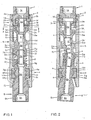
- figure 1 is a side sectional view of the preferred embodiment in the straight drilling configuration.
- Figure 2 is a view identical to that of fig. 1 with the tool actuated to the directional drilling configuration.
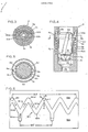
- Figure 3 is a sectional view taken along line 3-3 of figure 1.
- Figure 4 is a side elevation, rather enlarged and mostly cut away, of the
valve 6 of figures 1 and 2. - Figure 5 is a sectional view taken along line 5-5 of figure 4.
- Figure 6 is a development, further enlarged, of the outer surface of
sleeve 6b of figure 4. - Bearings and seals on downhole drilling machinery are an art in themselves and no point of novelty in this disclosure bears thereon. In some downhole machinery, bearings run in mud, some operate in an oil filled general enclosure, and some bearings are separately sealed. Bearings and seals shown in the drawings are conceptually adequate to demonstrate ability to practice the art disclosed but may be regarded as symbolic. Seal details are not shown but closures subject to contact or labyrinth sealing are simply captioned s.
- In the interest of descriptive clarity, features of manufacturing and maintenance utility, such as threaded connections and the like, are omitted unless they bear on points of novelty. For convenience it may be assumed that the various machine shapes are assembled by appropriate welding.
- Figures 1 and 2 are essentially identical with fig. 1 showing the straight drilling configuration and fig. 2 showing the directional drilling configuration. The deflection angle of fig. 2 is exaggerated. The actual deflection angle is usually less than two degrees.
-
Valve 6, in opening 5f, is too small for detailed description on the scale of figs. 1 and 2 and is described later. For fig. 1,valve 6 is open and fluid pressure inchannels valve 6 is actuated to resist fluid flow and fluid pressure inchannel 3a is higher than fluid pressure inchannel 5b. -
Input shaft 1 hastool joint box 1a for fluid tight connection to an upwardly continuing portion of a drill string. The input shaft is rotationally coupled tooutput shaft 9 by way offemale spline 1e and cooperatingmale spline 3e, flexjoint drive pin 3d and cooperatingarcuate slot 5e,arcuate slot 5k and cooperating flexjoint drive pin 7d and, finally,male spline 7c and cooperatingfemale spline 9f. The entire assembly of fig. 1 rotates together when rotationally driven by the upwardly continuing portion of the drill string becausespring 8 has pushed themidsection 5 upward causinglock lugs 5h to engage slots inlock flange 2c. The straightness ofmidsection 5 is assured by the engagement ofcam 5d andcam 2k. The entire assembly performs as a length of drill string and in the configuration of fig. 1, normal drilling continues. - Drilling fluid flows, generally unresisted, through
channels joint box 9a. The downwardly continuing drill string may comprise only a drill head. -
Mid-section shaft 5 can move a limited amount axially relative to the housing,input shaft 1, andoutput shaft 9. The movement is enabled by slip joints provided bysplined pair pair piston 3b when fluid pressure inchannel 3a, in fluid communication with the upper face of the piston, exceeds fluid pressure inchannel 5b, communicated to the lower face of the piston by way ofvent 5j and the housing general enclosure, by an amount sufficient for the piston to overcomespring 8. - Figure 2 shows the mid-section shaft moved downward in response to fluid flow restricting action of
valve 6 in response to drilling fluid flow manipulations to be described later herein. - When it is desirable to deflect the well bore, as drilling proceeds,
valve 6 is caused to actuate by processes yet to be described. Beforevalve 6 is actuated, the drill string is normally rotated until the downhole assembly is azimuthally oriented relative to earth by MWD procedures well known to those skilled in the drilling art. Whenvalve 6 is actuated, fluid flow therethrough is resisted and fluid pressure inchannel 5b is reduced relative to that inchannel 3a.Vent 5j feeds pressure fromchannel 5b into the housing general enclosure and causes a pressure differential acrosspiston 3b.Piston 3b moves downward incylinder 1d, compressingspring 8.Lock lug 5h is moved out of engagement withlock flange 2c.Housing 2 now has no rotational drive and remains stationary while the torque passing assembly inside rotates with the drill string.Optional stabilizer blades 2h engage the well bore wall. - When
midsection 5 moves downward,cam 5c engagescam 2e and forces the midsection to the right. In effect, these cams move the midsection and the housing in opposite radial directions. The gimbal formed byball 9d andsocket 4c becomes a fulcrum and the output shaft is angularly deflected from the housing centerline. The housing is on the same centerline as theinput shaft 1 which is journaled to the housing. -
Shaft 9 hasdrive pin 9h in arcuate slot 4b and bearingsurface 4a rotates in bearingbox 2g about the housing centerline. If the housing is not rotating and torque passing elements are rotating,cam 2e displaces the midsection in a fixed radial direction relative to earth. The center ofball 7b is a fixed point and theshaft 9c rotates about a fixed deflected centerline. - The
cams cams -
Bearing flange 2b andbearing box 1b represent a journal and thrust bearing arrangement that assures a coaxial relationship betweenshaft 1 andhousing 2. Flexjoint ball 3c andsocket 5a have centers on the housing centerline.Gimbal ball 9d andgimbal socket 4c have centers on the housing centerline and the centers are axially located in the housing by bearingblock 4a in bearingbox 2g.Actuator 3 moves axially but stays on the housing centerline.Seal 2a is not necessary if the housing is mud flooded. By-pass flow resistance may be adequate and is captioned(s)in fig. 2. -
Openings - The housing may be similar, externally, to a square drill collar. In that case,
stabilizer blades 2h would be omitted andhousing end 2j would accomplish well bore and housing alignment. - Figure 3 shows lock
flange 2c inhousing 2. Lockinglugs 5h comprise a wide lug 5ha and a narrow lug 5hb. The torque passing assembly can be locked to the housing in only one rotational position where lug 5ha enters flange opening 2ca and lug 5hb enters opening 2cb. - In figure 4,
valve 6 is shown to havepoppet 6c situated in the bore ofsleeve 6b.Poppet 6c is free to rotate and move axially within limits. Axial travel is limited bypins 6e moving inserpentine guideway 6m, better shown in the development of fig. 6.Coaxial sleeves spring 6j andspring collar 6n.Spring 6j, by way ofcollar 6n, urgespins 6e and theconnected poppet 6c upward.Pins 6e slide oncollar 6n to allow the poppet to rotate in a path dictated byserpentine groove 6m. - Fluid flowing downward in
channel 3a enters bore 6p ofvalve 6 and urgespoppet 6c downward. Some fluid may flow past the poppet periphery but most will flow throughturbine channels 6d. Thechannels 6d are spiral in shape and reaction to fluid flow produces forces that tend to rotate the poppet counterclockwise when viewed from the top. fluid flowing through the channels continue throughchannel 5b when the valve is open as shown. The valve can move downward under conditions to be described later andsurface 6f engagesseat surface 6k and block the previous fluid route tochannel 5b. - When the poppet is fully downward, fluid flowing through
channels 6d entersholes 6g and flows throughorifice 6h. The orifice is sized to give a preselected pressure differential betweenchannels channels - Figure 5 shows diametrically
opposite pins 6e and the relationships of the threechannels 6d. - Figure 6 is a development of the outer surface of
sleeve 6b which is cut in two by theserpentine groove 6m to form upper sleeve portion 6ba and lower portion 6bb. The development is viewed toward the centerline. Forces onpins 6e are shown by arrows. Bias force B is produced byspring 6j. Entrainment force E is produced by the action of the downward flowing fluid upon the poppet. Torque force T is produced by the turbine effect ofslots 6d. there are two pins but the movement description will address only the left pin. Starting with theleft pin 6e, the upward position shown results from spring force only. Fluid flow produces both E and T forces in preselected proportion and the pin moves along groove component 6ma and down into groove component 6mc. At this low point,poppet 6c will reachseat surface 6k and the tool will be actuated to the directional configuration by processes previously described herein. The tool and valve will stay actuated until fluid flow is reduced enough for bias force B to exceed Force E. - When fluid flow is reduced below a preselected amount,
pins 6e move upward.Pins 6e move along groove component 6mb as shown by the arrow therein. Some amount of force T remains as long as the pin is below portion 6md. At some low flow rate, the pins are at portion 6md. - When flow is again increased, forces E and T move the pins down portion 6me in the direction of the arrow. The pins then stop at portion 6mf and do not move down far enough for the poppet to reach
seat surface 6k and the tool stays in the straight configuration while fluid flow and drilling continues. - With the preferred serpentine form of the groove shown, the tool will change alternately between straight and directtional configuration in response to reduction of flow and subsequent increase of flow of preselected amounts and will do so continuously as long as the process is repeated.
-
Groove 6m can be of many serpentine forms. The poppet can be stopped before reaching the seat a number of times before being allowed to reach the seat and may be allowed to reach the seat any number of times before being stopped above the seat. By way of description then, the valve responds to drilling fluid flow increases within a preselected flow rate range to produce a mechanical signal. The mechanical signal is the movement of the poppet. The poppet movement produces an output signal in the form of a pressure differen tial across the poppet. The output signal characteristics, low pressure differential if the poppet is stopped above the orifice and high pressure differential if the poppet is allowed to reach the orifice, is determined by the number of times the drilling fluid flow rate is increased by the preselected amount. In effect, then, the tool assumes the straight drilling configuration in response to drilling fluid flow rate manipulations of a first characteristic and assumes the directional drilling configuration in response to drilling fluid flow rate manipulations of a second (or any other than the first) characteristic. - From the foregoing, it will be seen that this invention is one well adapted to attain all of the ends and objects hereinabove set forth, together with other advantages which are obvious and which are inherent to the method and apparatus.
- It will be understood that certain features and subcombinations are of utility and may be employed without reference to other features and subcombinations. This is contemplated by and is within the scope of the claims.
- As many possible embodiments may be made of the appratus and method of this invention without departing from the scope thereof, it is to be understood that all matter herein set forth or shown in the accompanying drawings is to be interpreted as illustrative and not in a limiting sense.
Claims (9)
1. A controllable directional drilling tool for use on a fluid conducting drill string in a well bore, the tool comprising:
a) an elongate, outer, orientable housing having well bore wall engegement surfaces to generally align said housing in said bore, an upper end, a lower end, and a general centerline;
b) an inner, flexible, torque passing member arranged for rotation of a drill head, journaled within said housing, with means at an upper end for fluid tight attachment to an upwardly continuing portion of a drill string, means at the lower end for fluid tight attachment to a downwardly continuing portion of said drill string, and at least one fluid channel arranged to conduct drilling fluid between said portions of said drill string;
c) a remote control selector valve situated to variably resist the flow of drilling fluid through said channel in response to increase in drilling fluid flow rate greater than a preselected amount, said valve responsive to drilling fluid flow rate manipulations having first characteristics to provide a first amount of fluid flow resistance and responsive to drilling fluid flow rate manipulations of second characteristics to provide a second amount of fluid flow resistance smaller than said first amount;
d) deflector means, responsive to said first amount of fluid flow resistance, to deflect, with respect to the orientation of said housing, said torque passing member; and
e) coupler means, responsive to said fluid flow resistance to rotationally couple said torque passing member to said housing in response to said second amount, and responsive to said first amount to decouple said torque passing member from said housing.
2. A well bore deviation control tool for use on a fluid conducting drill string in a well being drilled, the tool comprising:
a) an elongated generally cylindrical housing having an upper end, a lower end, and a general centerline;
b) a torque passing assembly extending along said general centerline, arranged for rotating therein and comprising, an input shaft journaled for rotation on said general centerline and having means for fluid tight attachment to an upwardly continuing portion of a drill string, an output shaft bearingly supported for rotation in said housing and extending from said lower end thereof with means for fluid tight attachment to a downwardly continuing portion of the drill string, a rigid mid-section shaft rotationally coupled by flexible joints between said input shaft and said output shaft, and at least one drilling fluid channel extending longitudinally through said assembly;
c) well bore wall engagement surfaces on said housing to generally align said housing and the well bore;
d) selector valve means situated in said channel and arranged to variably resist drilling fluid flow therethrough, responsive to drilling fluid flow rate changes of a first characteristic to produce a first fluid flow resistance when drilling fluid flow rate is increased a preselected amount and responsive to drilling fluid flow rate changes of other characteristics to produce a higher fluid flow resistance than said first flow resistance when drilling fluid flow is increased said preselected amount;
e) actuator means situated in said assembly, responsive to fluid flow resistance across said valve to move from a first position to a second position in response to said higher fluid flow resistance than said first fluid flow resistance;
f) bias means situated on said assembly and arranged to move said actuator to said first position in response to said first fluid flow resistance;
g) lateral displacement means mounted on said assembly, and responsive to movement of said actuator means to move said mid-section shaft a preselected radial distance relative to said housing when said actuator moves to said second position;
h) gimbal mounting means in said housing arranged to rotationally support said output shaft for rotation about an angularly deflected axis relative to said centerline, said gimbal mounting means to serve as a fulcrum to deflect said angularly deflected axis when said mid-section shaft is moved said radial distance; and
i) rotational coupling means, responsive to said positions of said actuator means, arranged to rotationally couple said assembly to said housing when said actuator is in said first position and to rotationally decouple said assembly from said housing when said actuator is in said second position.
3. The tool of claim 2 wherein said actuator means comprises a variable volume actuator chamber with fluid communication channels to opposite fluid flow related sides of said valve.
4. The tool of claim 2 wherein said lateral displacement means comprises a first cam mounted for movement on said assembly, responsive to movement of said actuator, and is arranged to engage a cooperating cam surface on said housing to move said mid-section said radial distance.
5. The tool of claim 4 wherein said first cam has a first cam surface arranged to produce said radial displacement when said actuator is in said second position and a second cam surface arranged to engage a cooperating surface on said housing to move said mid-section shaft to a generally central position when said actuator is in said first position.
6. The tool of claim 2 wherein said gimbal mounting means comprises a bearing arranged for radial and axial support of said output shaft in said housing and has a spherical socket to support a cooperating spherical surface on said output shaft to accomodate rotation of said output shaft about an axis angularly deflected from said centerline.
7. The tool of claim 2 wherein said rotational coupling means is arranged to rotationally couple said assembly to said housing only when said assembly has a preselected rotational orientation relative to said housing.
8. The tool of claim 7 wherein said rotational coupling means comprises at least one element on said assembly that interdigitatingly engages a cooperating element on said housing and said interdigitating element is arranged to be compatible with said cooperating element only when said assembly is in a preselected rotational orientation relative to said housing.
9. The tool of claim 2 wherein said housing has radially extended stabilizer surfaces to engage the well bore wall.
Applications Claiming Priority (2)
| Application Number | Priority Date | Filing Date | Title |
|---|---|---|---|
| US272787 | 1988-11-18 | ||
| US07/272,787 US4895214A (en) | 1988-11-18 | 1988-11-18 | Directional drilling tool |
Publications (2)
| Publication Number | Publication Date |
|---|---|
| EP0369745A2 true EP0369745A2 (en) | 1990-05-23 |
| EP0369745A3 EP0369745A3 (en) | 1991-09-25 |
Family
ID=23041277
Family Applications (1)
| Application Number | Title | Priority Date | Filing Date |
|---|---|---|---|
| EP19890311782 Withdrawn EP0369745A3 (en) | 1988-11-18 | 1989-11-14 | Directional drilling tool |
Country Status (3)
| Country | Link |
|---|---|
| US (1) | US4895214A (en) |
| EP (1) | EP0369745A3 (en) |
| CA (1) | CA2002594A1 (en) |
Cited By (5)
| Publication number | Priority date | Publication date | Assignee | Title |
|---|---|---|---|---|
| EP0497420A1 (en) * | 1991-02-01 | 1992-08-05 | Anadrill International SA | Directional drilling methods and apparatus |
| WO1995026454A3 (en) * | 1994-03-25 | 1995-11-30 | Amoco Corp | Curved drilling apparatus |
| EP0763647A3 (en) * | 1995-09-14 | 1998-12-23 | Anadrill International SA | Steerable drilling tool and system |
| EP0994236A3 (en) * | 1998-10-12 | 2001-03-21 | Pilot Drilling Control Limited | Indexing mechanism |
| RU2235180C2 (en) * | 2002-07-29 | 2004-08-27 | Открытое акционерное общество Научно-производственное объединение "Буровая техника" | Device for directional drilling |
Families Citing this family (65)
| Publication number | Priority date | Publication date | Assignee | Title |
|---|---|---|---|---|
| FR2659383B1 (en) * | 1990-03-07 | 1992-07-10 | Inst Francais Du Petrole | ROTARY DRILLING DEVICE COMPRISING MEANS FOR ADJUSTING THE TRAJECTORY OF THE DRILLING TOOL IN AZIMUTES AND CORRESPONDING DRILLING METHOD. |
| WO1992008872A1 (en) * | 1990-11-19 | 1992-05-29 | Den Norske Stats Oljeselskap A.S | Converter group and pressure converter for use therein |
| FR2670824B1 (en) * | 1990-12-21 | 1997-01-24 | Inst Francais Du Petrole | DEVICE FOR THE REMOTE OPERATION OF EQUIPMENT COMPRISING A HARD / NEEDLE SYSTEM AND ITS APPLICATION TO A DRILLING LINING. |
| FR2671130B1 (en) * | 1990-12-28 | 1993-04-23 | Inst Francais Du Petrole | DEVICE COMPRISING TWO ELEMENTS ARTICULATED IN A PLANE, APPLIED TO DRILLING EQUIPMENT. |
| US5117927A (en) * | 1991-02-01 | 1992-06-02 | Anadrill | Downhole adjustable bent assemblies |
| US5213168A (en) * | 1991-11-01 | 1993-05-25 | Amoco Corporation | Apparatus for drilling a curved subterranean borehole |
| US5259467A (en) * | 1992-04-09 | 1993-11-09 | Schoeffler William N | Directional drilling tool |
| US5445230A (en) * | 1993-10-01 | 1995-08-29 | Wattenburg; Willard H. | Downhole drilling subassembly and method for same |
| US5673765A (en) * | 1993-10-01 | 1997-10-07 | Wattenburg; Willard H. | Downhole drilling subassembly and method for same |
| RU2112128C1 (en) * | 1994-01-05 | 1998-05-27 | Государственное научно-производственное предприятие "Пилот" | Gear for directed drilling |
| US5450914A (en) * | 1994-02-18 | 1995-09-19 | Precision Radius, Inc. | Fluid powered stepping motor for rotating a downhole assembly relative to a supporting pipe string |
| US5484029A (en) * | 1994-08-05 | 1996-01-16 | Schlumberger Technology Corporation | Steerable drilling tool and system |
| US5503235A (en) * | 1994-11-28 | 1996-04-02 | Falgout, Sr.; Thomas E. | Directional drilling control method |
| DE59609624D1 (en) * | 1996-06-07 | 2002-10-10 | Baker Hughes Inc | Control device for a directional drilling tool |
| US5957222A (en) * | 1997-06-10 | 1999-09-28 | Charles T. Webb | Directional drilling system |
| GB9801644D0 (en) | 1998-01-28 | 1998-03-25 | Neyrfor Weir Ltd | Improvements in or relating to directional drilling |
| US6092610A (en) * | 1998-02-05 | 2000-07-25 | Schlumberger Technology Corporation | Actively controlled rotary steerable system and method for drilling wells |
| WO1999064712A1 (en) * | 1998-06-08 | 1999-12-16 | Webb Charles T | Directional drilling system and apparatus |
| US6158529A (en) * | 1998-12-11 | 2000-12-12 | Schlumberger Technology Corporation | Rotary steerable well drilling system utilizing sliding sleeve |
| US6318481B1 (en) | 1998-12-18 | 2001-11-20 | Quantum Drilling Motors, Inc. | Drill string deflector sub |
| US6213205B1 (en) | 1999-02-25 | 2001-04-10 | Halliburton Energy Services, Inc. | Pressure activated bendable tool |
| US6109372A (en) * | 1999-03-15 | 2000-08-29 | Schlumberger Technology Corporation | Rotary steerable well drilling system utilizing hydraulic servo-loop |
| US7136795B2 (en) | 1999-11-10 | 2006-11-14 | Schlumberger Technology Corporation | Control method for use with a steerable drilling system |
| DE60011587T2 (en) | 1999-11-10 | 2005-06-30 | Schlumberger Holdings Ltd., Road Town | CONTROL PROCEDURE FOR CONTROLLABLE DRILLING SYSTEM |
| US6364034B1 (en) | 2000-02-08 | 2002-04-02 | William N Schoeffler | Directional drilling apparatus |
| CA2307514C (en) * | 2000-04-28 | 2003-11-04 | Halliburton Energy Services, Inc. | Piston actuator assembly for an orienting device |
| US6394193B1 (en) | 2000-07-19 | 2002-05-28 | Shlumberger Technology Corporation | Downhole adjustable bent housing for directional drilling |
| US6474415B1 (en) | 2000-11-15 | 2002-11-05 | Schlumberger Technology Corporation | Method and apparatus for milling openings in downhole structures |
| US7188685B2 (en) | 2001-12-19 | 2007-03-13 | Schlumberge Technology Corporation | Hybrid rotary steerable system |
| WO2003096075A1 (en) | 2002-05-13 | 2003-11-20 | Camco International (Uk) Limited | Recalibration of downhole sensors |
| US6827158B1 (en) * | 2002-07-31 | 2004-12-07 | The Charles Machine Works, Inc. | Two-pipe on-grade directional boring tool and method |
| RU2244795C1 (en) * | 2003-08-11 | 2005-01-20 | Илясов Валерий Николаевич | Device for drilling slanting-horizontal wells |
| GB0521693D0 (en) * | 2005-10-25 | 2005-11-30 | Reedhycalog Uk Ltd | Representation of whirl in fixed cutter drill bits |
| US8522897B2 (en) | 2005-11-21 | 2013-09-03 | Schlumberger Technology Corporation | Lead the bit rotary steerable tool |
| US8360174B2 (en) * | 2006-03-23 | 2013-01-29 | Schlumberger Technology Corporation | Lead the bit rotary steerable tool |
| US8297375B2 (en) | 2005-11-21 | 2012-10-30 | Schlumberger Technology Corporation | Downhole turbine |
| US8408336B2 (en) | 2005-11-21 | 2013-04-02 | Schlumberger Technology Corporation | Flow guide actuation |
| US7571780B2 (en) * | 2006-03-24 | 2009-08-11 | Hall David R | Jack element for a drill bit |
| US20080142268A1 (en) * | 2006-12-13 | 2008-06-19 | Geoffrey Downton | Rotary steerable drilling apparatus and method |
| GB2455734B (en) | 2007-12-19 | 2010-03-24 | Schlumberger Holdings | Steerable system |
| GB2457497B (en) | 2008-02-15 | 2012-08-08 | Pilot Drilling Control Ltd | Flow stop valve |
| US9133674B2 (en) | 2009-02-24 | 2015-09-15 | Schlumberger Technology Corporation | Downhole tool actuation having a seat with a fluid by-pass |
| US8371400B2 (en) * | 2009-02-24 | 2013-02-12 | Schlumberger Technology Corporation | Downhole tool actuation |
| US7669663B1 (en) | 2009-04-16 | 2010-03-02 | Hall David R | Resettable actuator for downhole tool |
| EP2467561B1 (en) | 2009-08-18 | 2017-03-15 | Pilot Drilling Control Limited | Flow stop valve |
| US8353354B2 (en) | 2010-07-14 | 2013-01-15 | Hall David R | Crawler system for an earth boring system |
| US8172009B2 (en) | 2010-07-14 | 2012-05-08 | Hall David R | Expandable tool with at least one blade that locks in place through a wedging effect |
| US8281880B2 (en) | 2010-07-14 | 2012-10-09 | Hall David R | Expandable tool for an earth boring system |
| FR2963945B1 (en) | 2010-08-20 | 2013-05-10 | Breakthrough Design | ANNULAR DEVICE FOR RADIAL MOVEMENT OF CONNECTED ORGANS BETWEEN THEM |
| US8365821B2 (en) | 2010-10-29 | 2013-02-05 | Hall David R | System for a downhole string with a downhole valve |
| US8640768B2 (en) | 2010-10-29 | 2014-02-04 | David R. Hall | Sintered polycrystalline diamond tubular members |
| AU2013257160A1 (en) * | 2012-05-04 | 2014-10-30 | Tempress Technologies, Inc. | Steerable gas turbodrill |
| GB201214784D0 (en) * | 2012-08-20 | 2012-10-03 | Smart Stabilizer Systems Ltd | Articulating component of a downhole assembly |
| US9371696B2 (en) | 2012-12-28 | 2016-06-21 | Baker Hughes Incorporated | Apparatus and method for drilling deviated wellbores that utilizes an internally tilted drive shaft in a drilling assembly |
| US9366087B2 (en) * | 2013-01-29 | 2016-06-14 | Schlumberger Technology Corporation | High dogleg steerable tool |
| WO2015142333A1 (en) | 2014-03-20 | 2015-09-24 | Halliburton Energy Services, Inc. | Automated locking joint in a wellbore tool string |
| US9206649B1 (en) | 2014-06-24 | 2015-12-08 | Pine Tree Gas, Llc | Systems and methods for drilling wellbores having a short radius of curvature |
| US20160168944A1 (en) * | 2014-12-11 | 2016-06-16 | Schlumberger Technology Corporation | Setting Sleeve |
| US11261667B2 (en) * | 2015-03-24 | 2022-03-01 | Baker Hughes, A Ge Company, Llc | Self-adjusting directional drilling apparatus and methods for drilling directional wells |
| CN107939290B (en) * | 2017-12-11 | 2024-01-05 | 德州联合石油科技股份有限公司 | Static pointing type rotary steering drilling tool actuating mechanism |
| US11193331B2 (en) | 2019-06-12 | 2021-12-07 | Baker Hughes Oilfield Operations Llc | Self initiating bend motor for coil tubing drilling |
| US12331604B2 (en) * | 2022-10-31 | 2025-06-17 | Arrival Energy Solutions Inc. | Indexing control system |
| CN115788297A (en) * | 2022-12-02 | 2023-03-14 | 北京中煤矿山工程有限公司 | Rectangular-section excavating equipment |
| FR3143061B1 (en) * | 2022-12-08 | 2024-12-13 | Breakthrough Design | Device for guiding the rotation of a drilling tool and associated method |
| CN119352899A (en) * | 2024-12-24 | 2025-01-24 | 中国石油集团西部钻探工程有限公司 | Downhole rotary guide device and adjustment method for oil production |
Family Cites Families (7)
| Publication number | Priority date | Publication date | Assignee | Title |
|---|---|---|---|---|
| US2819040A (en) * | 1956-07-13 | 1958-01-07 | Eastman Oil Well Survey Co | Deflecting tool |
| SU969881A1 (en) * | 1981-04-02 | 1982-10-30 | Всесоюзный Ордена Трудового Красного Знамени Научно-Исследовательский Институт Буровой Техники | Deflector for drilling directional wells |
| US4732223A (en) * | 1984-06-12 | 1988-03-22 | Universal Downhole Controls, Ltd. | Controllable downhole directional drilling tool |
| US4597454A (en) * | 1984-06-12 | 1986-07-01 | Schoeffler William N | Controllable downhole directional drilling tool and method |
| US4655299A (en) * | 1985-10-04 | 1987-04-07 | Petro-Design, Inc. | Angle deviation tool |
| US4655289A (en) * | 1985-10-04 | 1987-04-07 | Petro-Design, Inc. | Remote control selector valve |
| US4811798A (en) * | 1986-10-30 | 1989-03-14 | Team Construction And Fabrication, Inc. | Drilling motor deviation tool |
-
1988
- 1988-11-18 US US07/272,787 patent/US4895214A/en not_active Expired - Fee Related
-
1989
- 1989-11-09 CA CA002002594A patent/CA2002594A1/en not_active Abandoned
- 1989-11-14 EP EP19890311782 patent/EP0369745A3/en not_active Withdrawn
Cited By (5)
| Publication number | Priority date | Publication date | Assignee | Title |
|---|---|---|---|---|
| EP0497420A1 (en) * | 1991-02-01 | 1992-08-05 | Anadrill International SA | Directional drilling methods and apparatus |
| WO1995026454A3 (en) * | 1994-03-25 | 1995-11-30 | Amoco Corp | Curved drilling apparatus |
| EP0763647A3 (en) * | 1995-09-14 | 1998-12-23 | Anadrill International SA | Steerable drilling tool and system |
| EP0994236A3 (en) * | 1998-10-12 | 2001-03-21 | Pilot Drilling Control Limited | Indexing mechanism |
| RU2235180C2 (en) * | 2002-07-29 | 2004-08-27 | Открытое акционерное общество Научно-производственное объединение "Буровая техника" | Device for directional drilling |
Also Published As
| Publication number | Publication date |
|---|---|
| CA2002594A1 (en) | 1990-05-18 |
| EP0369745A3 (en) | 1991-09-25 |
| US4895214A (en) | 1990-01-23 |
Similar Documents
| Publication | Publication Date | Title |
|---|---|---|
| US4895214A (en) | Directional drilling tool | |
| US5316093A (en) | Fitting for controlled trajectory drilling, comprising a variable geometry stabilizer and use of this fitting | |
| US5495900A (en) | Drill string deflection sub | |
| US5232058A (en) | Equipment for a drilling fitting comprising an element to be actuated, a motor and control means | |
| US4811798A (en) | Drilling motor deviation tool | |
| DE60202097T2 (en) | Steerable rotary drilling tool | |
| EP0571045B1 (en) | Directional drilling with downhole motor on coiled tubing | |
| US5273123A (en) | Fitting for controlled trajectory drilling, comprising a variable angle elbow element and use of this fitting | |
| DE68914286T2 (en) | DIRECTIONAL DRILLING DEVICE AND METHOD. | |
| US4286676A (en) | Crank connector for directional drilling | |
| EP0763647B1 (en) | Steerable drilling tool and system | |
| CA2587738C (en) | Orientation tool | |
| US5259467A (en) | Directional drilling tool | |
| US12203368B2 (en) | Rotary steerable drilling assembly and method | |
| US20090166089A1 (en) | Drilling Tool Steering Device | |
| US5503235A (en) | Directional drilling control method | |
| EP0695850A2 (en) | Steerable drilling tool and system | |
| DE112010003039T5 (en) | Slip ring device for a steerable turning tool | |
| US4374547A (en) | Crank connector for directional drilling | |
| US5775444A (en) | Drill string orienting motor | |
| US4928776A (en) | Deviation control tool | |
| US4834196A (en) | Well drilling tool | |
| US5297641A (en) | Drilling deviation control tool | |
| CA2382596C (en) | Directional well drilling | |
| GB2085055A (en) | Crank Connectors for Directional Drilling |
Legal Events
| Date | Code | Title | Description |
|---|---|---|---|
| PUAI | Public reference made under article 153(3) epc to a published international application that has entered the european phase |
Free format text: ORIGINAL CODE: 0009012 |
|
| AK | Designated contracting states |
Kind code of ref document: A2 Designated state(s): AT BE DE FR GB IT NL SE |
|
| PUAL | Search report despatched |
Free format text: ORIGINAL CODE: 0009013 |
|
| AK | Designated contracting states |
Kind code of ref document: A3 Designated state(s): AT BE DE FR GB IT NL SE |
|
| STAA | Information on the status of an ep patent application or granted ep patent |
Free format text: STATUS: THE APPLICATION IS DEEMED TO BE WITHDRAWN |
|
| 18D | Application deemed to be withdrawn |
Effective date: 19920326 |