EP0369799B1 - Magnetische Fensterscheibendichtung - Google Patents
Magnetische Fensterscheibendichtung Download PDFInfo
- Publication number
- EP0369799B1 EP0369799B1 EP89311900A EP89311900A EP0369799B1 EP 0369799 B1 EP0369799 B1 EP 0369799B1 EP 89311900 A EP89311900 A EP 89311900A EP 89311900 A EP89311900 A EP 89311900A EP 0369799 B1 EP0369799 B1 EP 0369799B1
- Authority
- EP
- European Patent Office
- Prior art keywords
- windowpane
- seal assembly
- vehicle
- sealing strip
- window
- Prior art date
- Legal status (The legal status is an assumption and is not a legal conclusion. Google has not performed a legal analysis and makes no representation as to the accuracy of the status listed.)
- Expired - Lifetime
Links
- 238000007789 sealing Methods 0.000 claims description 86
- 241001074085 Scophthalmus aquosus Species 0.000 claims description 83
- 230000006835 compression Effects 0.000 claims description 11
- 238000007906 compression Methods 0.000 claims description 11
- CWYNVVGOOAEACU-UHFFFAOYSA-N Fe2+ Chemical compound [Fe+2] CWYNVVGOOAEACU-UHFFFAOYSA-N 0.000 claims description 7
- 239000002184 metal Substances 0.000 claims description 7
- 229910052751 metal Inorganic materials 0.000 claims description 7
- 239000000919 ceramic Substances 0.000 claims description 6
- 230000003247 decreasing effect Effects 0.000 claims description 4
- 230000000295 complement effect Effects 0.000 claims description 3
- 229920001971 elastomer Polymers 0.000 claims description 2
- 239000005060 rubber Substances 0.000 claims description 2
- 239000000463 material Substances 0.000 description 6
- 238000000576 coating method Methods 0.000 description 4
- 230000007423 decrease Effects 0.000 description 4
- XEEYBQQBJWHFJM-UHFFFAOYSA-N Iron Chemical compound [Fe] XEEYBQQBJWHFJM-UHFFFAOYSA-N 0.000 description 3
- 239000011248 coating agent Substances 0.000 description 3
- 230000001419 dependent effect Effects 0.000 description 2
- 239000004677 Nylon Substances 0.000 description 1
- 229910000831 Steel Inorganic materials 0.000 description 1
- 239000004809 Teflon Substances 0.000 description 1
- 229920006362 Teflon® Polymers 0.000 description 1
- 239000000853 adhesive Substances 0.000 description 1
- 230000001070 adhesive effect Effects 0.000 description 1
- 239000002390 adhesive tape Substances 0.000 description 1
- 238000013459 approach Methods 0.000 description 1
- 230000000712 assembly Effects 0.000 description 1
- 238000000429 assembly Methods 0.000 description 1
- 230000000694 effects Effects 0.000 description 1
- 239000013536 elastomeric material Substances 0.000 description 1
- 230000008030 elimination Effects 0.000 description 1
- 238000003379 elimination reaction Methods 0.000 description 1
- 230000004907 flux Effects 0.000 description 1
- 239000011521 glass Substances 0.000 description 1
- 229910052742 iron Inorganic materials 0.000 description 1
- 230000003137 locomotive effect Effects 0.000 description 1
- 239000006249 magnetic particle Substances 0.000 description 1
- 230000005389 magnetism Effects 0.000 description 1
- 238000000034 method Methods 0.000 description 1
- 229920003052 natural elastomer Polymers 0.000 description 1
- 229920001194 natural rubber Polymers 0.000 description 1
- 229920001778 nylon Polymers 0.000 description 1
- 239000002245 particle Substances 0.000 description 1
- 239000004033 plastic Substances 0.000 description 1
- 229920003023 plastic Polymers 0.000 description 1
- 229920000728 polyester Polymers 0.000 description 1
- 229920002635 polyurethane Polymers 0.000 description 1
- 239000004814 polyurethane Substances 0.000 description 1
- 229920000915 polyvinyl chloride Polymers 0.000 description 1
- 239000004800 polyvinyl chloride Substances 0.000 description 1
- 239000000843 powder Substances 0.000 description 1
- 229910052710 silicon Inorganic materials 0.000 description 1
- 239000010703 silicon Substances 0.000 description 1
- 239000010959 steel Substances 0.000 description 1
- 229920003051 synthetic elastomer Polymers 0.000 description 1
- 239000005061 synthetic rubber Substances 0.000 description 1
Images

Classifications
-
- B—PERFORMING OPERATIONS; TRANSPORTING
- B60—VEHICLES IN GENERAL
- B60J—WINDOWS, WINDSCREENS, NON-FIXED ROOFS, DOORS, OR SIMILAR DEVICES FOR VEHICLES; REMOVABLE EXTERNAL PROTECTIVE COVERINGS SPECIALLY ADAPTED FOR VEHICLES
- B60J1/00—Windows; Windscreens; Accessories therefor
-
- B—PERFORMING OPERATIONS; TRANSPORTING
- B60—VEHICLES IN GENERAL
- B60J—WINDOWS, WINDSCREENS, NON-FIXED ROOFS, DOORS, OR SIMILAR DEVICES FOR VEHICLES; REMOVABLE EXTERNAL PROTECTIVE COVERINGS SPECIALLY ADAPTED FOR VEHICLES
- B60J10/00—Sealing arrangements
- B60J10/70—Sealing arrangements specially adapted for windows or windscreens
- B60J10/74—Sealing arrangements specially adapted for windows or windscreens for sliding window panes, e.g. sash guides
- B60J10/79—Sealing arrangements specially adapted for windows or windscreens for sliding window panes, e.g. sash guides for flush-glass windows, i.e. for windows flush with the vehicle body or the window frame
-
- B—PERFORMING OPERATIONS; TRANSPORTING
- B60—VEHICLES IN GENERAL
- B60J—WINDOWS, WINDSCREENS, NON-FIXED ROOFS, DOORS, OR SIMILAR DEVICES FOR VEHICLES; REMOVABLE EXTERNAL PROTECTIVE COVERINGS SPECIALLY ADAPTED FOR VEHICLES
- B60J10/00—Sealing arrangements
- B60J10/20—Sealing arrangements characterised by the shape
- B60J10/24—Sealing arrangements characterised by the shape having tubular parts
-
- B—PERFORMING OPERATIONS; TRANSPORTING
- B60—VEHICLES IN GENERAL
- B60J—WINDOWS, WINDSCREENS, NON-FIXED ROOFS, DOORS, OR SIMILAR DEVICES FOR VEHICLES; REMOVABLE EXTERNAL PROTECTIVE COVERINGS SPECIALLY ADAPTED FOR VEHICLES
- B60J10/00—Sealing arrangements
- B60J10/30—Sealing arrangements characterised by the fastening means
- B60J10/38—Sealing arrangements characterised by the fastening means using magnetic means
Definitions
- the present invention relates to a frameless window assembly using a magnetic seal and having a movable windowpane capable of having all edges flush with the adjacent vehicle body panel.
- full flush window systems pose unique problems with respect to windowpane movement. For example, since a full flush windowpane is flush with the vehicle body at the beltline, opening of the window requires lateral or transverse inward movement of the windowpane at the beltline prior to its descent into the tracking channel in the vehicle door. Conventional framed automotive windows do not permit such lateral or transverse movement of the windowpane. Although elimination of window framework to allow for such movement would circumvent this problem, it is difficult to achieve a satisfactory window seal in frameless systems using conventional sealing techniques.
- automotive windows are conventionally sealed using elastomeric strips which depend primarily upon compression for their sealing force.
- the use of conventional sealing strips generally requires higher compression to form an adequate seal, making it difficult to open and close the windows of the vehicle.
- repeated compression of a sealing strip particularly one requiring high compressive force for sealing, shortens the effective sealing life of the strip. If less compression of the strip is used to offset these problems, the integrity of the seal between the windowpane and vehicle body is reduced. This leads to increased windowpane flutter, wind noise and air entering the passenger compartment during operation of the vehicle.
- a full flush or a frameless window assembly having a satisfactory seal between the window and the automotive body. It would also be desirable to provide a window assembly in which the sealing force is not entirely dependent upon the compression of the sealing member. It would further be desirable to provide a satisfactory window assembly including a window which is opened and closed by a camming mechanism, in which the sealing member does not offer undue compressive resistance to lateral or transverse movement of the windowpane at the beltline. It would also be desirable to provide a magnetic window assembly in a frameless system in which the door can be easily opened with the windowpane in the ascended, i.e. window opening closed, position.
- US-4535563 discloses a window assembly having the features of the precharacterizing portion of claim 1.
- a window assembly in an automotive vehicle comprising:-
- said mounting portion of the seal assembly is mounted on said vehicle and said second magnetic element is associated with, or forms part of, an edge portion of the windowpane.
- said mounting portion of the seal assembly is mounted on an edge portion of the windowpane and said second magnetic element is associated with, or forms part of, the vehicle.
- said compressible body portion of the seal assembly includes a common wall, an outer wall and side walls extending therebetween, said walls defining a hollow interior of said body portion; said mounting portion of the seal assembly, for attaching said sealing strip to said one of said adjacent body panels of the vehicle, extends from and shares said common wall with said body portion; said first magnetic element of the seal assembly is embedded in said outer wall of said body portion; and said second magnetic element of the seal assembly complementary to said first magnetic element, is attached to a lateral edge of said windowpane for cooperative engagement with said first magnetic element.
- said side walls are bellowed, and:- with the windowpane in a closed position, said sealing strip is compressively tapered by selective compression of said body portion along the length of said sealing strip, causing at least a portion of said bellowed side walls to compress in an accordion-like fashion.
- said windowpane is located between the beltline and roofline of said vehicle and forward of the B-pillar of said vehicle, and:- said mounting portion of the seal assembly is a U-shaped mounting portion, for attaching said sealing strip to said adjacent side panels of the vehicle, said U-shaped mounting portion defining a U-shaped channel and said mounting portion including gripping ribs extending into said U-shaped channel; and:- said U-shaped mounting portion of the seal assembly is mounted on a lateral edge of said B pillar adjacent to said lateral edge of said windowpane, and:- said sealing strip of the sealing assembly is compressively tapered when in sealing engagement with said adjacent body panels of the vehicle and said windowpane, said sealing strip being less compressed at the beltline relative to the roofline of the vehicle.
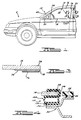
- Automotive vehicle V has a window opening 12 for a side windowpane 14.
- Window opening 12 is generally defined by roofline 16, beltline 18, mirror panel 20, and B pillar 22, with mirror panel 20 and B pillar 22 respectively defining the forward 24 and rearward 26 tracking lines for windowpane movement.
- window seal assembly 10 sealingly engages the lateral edge portions of windowpane 14 adjacent to mirror panel 20 and B pillar 22.
- FIG 2 is a partial cross-section taken along the line 2-2 of Figure 1, window seal assembly 10 used in the present invention is shown engaging lateral edge portion 28 of windowpane 14 and B pillar 22.
- B pillar 22 generally comprises inner sheet metal 30 and outer sheet metal 32 pinch-welded together to form pillar flanges 34 and 36.
- a decorative applique 38 of glass or plastic or the like can be attached to the outer surface of B pillar 22 by conventional means such as an adhesive 40 or double-sided adhesive tape.
- Mirror panel 20 also generally comprises two sheets of metal pinch-welded together to form a panel flange (not shown in the Figures), generally extending along forward tracking line 24, which provides a point of attachment for window seal assembly 10, similar to B pillar flange 36 described below.
- window seal assembly 10 is described below in relation to lateral edge 28 of windowpane 14 and flange 36 of B pillar 22, it should be understood that a similar arrangement of window seal assembly 10 is provided between the flange of mirror panel 20 and the lateral edge portion of windowpane 14 proximate thereto. It should also be appreciated that in vehicles lacking a mirror panel, the window seal assembly can instead directly engage the A pillar 42 of the vehicle.
- any panel, pillar or the like providing a forward tracking line for windowpane and a suitable point of attachment for windowpane seal assembly as described below can be utilized.
- window seal assembly 10 comprises a flexible sealing strip 44 which, in the section shown in Figure 2, is mounted on flange 36 of B pillar 22.
- Sealing strip 44 comprises a generally tubular body portion 46 and a U-shaped mounting portion 48 extending from and sharing common wall 50 with body portion 46.
- common and outer walls 50, 52 and side walls 54, 56 cooperate to define a hollow body interior 58 which extends at least substantially the entire length of sealing strip 44.
- the hollow tubular structure and side wall bellows of body portion 46 permit variable compression and expansion of body portion 46 of sealing strip 44 by an "accordian-like" action.
- Sealing strip 44 can be constructed of a conventional elastomeric material suitable for use in the sealing strip art. Suitable materials include polyvinyl chloride, natural or synthetic rubber, or the like. Preferably sealing strip 44 is comprised of rubber. Outer wall 52 of sealing strip 44 can also include a friction-reducing coating on its outer surface 60 to facilitate sliding of windowpane 14 into its ascended or descended positions. Alternatively, a friction-reducing coating can be provided on the opposing surface 62 of the second magnetic element 72 (to be described below), or on both surfaces 60 and 62. Suitable coating materials including low-friction coatings such as teflon, polyurethane and silicon, or flocking comprised of nylon or polyester.
- U-shaped mounting portion 48 of sealing strip 44 defines a U-shaped channel 64 for mounting sealing strip 44 onto flange 36 of B pillar 22.
- U-shaped mounting portion 48 is also provided with one or more gripping ribs 66 extending into U-shaped channel 64 which help maintain sealing strip 44 in position on flange 36.
- sealing strip 44 be provided with a metal core element 68, as is conventional in the art, for additional structural and gripping strength.
- sealing strip 44 further comprises a first magnetic element 70 embedded in outer wall 52 of body portion 46.
- Magnetic element 70 generally comprises either a permanent magnet or a ferrous material such as iron or steel.
- first magnetic element 70 may be in the form of a strip, particles, powder or the like, magnetic element 70 is preferably provided in the form of a strip which extends substantially the length of sealing strip 44.
- flexible elastomeric magnets such as those commonly used in refrigerator seals and which can be coextruded with sealing strip 44.
- window seal assembly 10 further comprises a second magnetic element 72 complementary to first magnetic element 70, mounted onto lateral edge portion 28 of side windowpane 14.
- Windowpane 14 is preferably provided with a ceramic layer 74 to which second magnetic element 72 is adhesively attached.
- Second magnetic element 72 also comprises a permanent magnet or a ferrous material as described with respect to first magnetic element 70.
- second magnetic element 76 mounted on edge portion 28 of windowpane 14 is depicted in Figure 3.
- second magnetic element 76 is provided with a nonmagnetic rim 78 which is in turn attached or adhesively bonded to ceramic layer 74.
- the second magnetic element can be provided directly in the ceramic layer by the addition of iron powder, magnetic particles, and the like, or can be directly attached to the window without an intermediate ceramic layer.
- both elements can be permanent magnets.
- permanent magnets with multiple pole magnetism patterns are used for magnetic elements, their orientation must be vertical such that each magnetic field is continuous for the entire length of the sealing portion strip.
- first and second magnetic elements herein described preferably comprise combinations of permanent magnets and ferrous materials, the magnetic aspect of the window seal assembly used in the present invention can instead be provided by electromagnetic means.
- window seal assembly 110 also comprises a flexible sealing strip 144 with a first magnetic element 170 embedded therein.
- sealing strip 144 is mounted directly on lateral edge portion 28 of side windowpane 14 by its U-shaped mounting portion 148.
- Second magnetic element 172 can be provided by the metal of the B pillar 22 of the vehicle body as shown in Figure 4, or, alternatively, in the form of a strip of magnetic or ferrous material (not shown in the Figures) attached thereto.
- FIG. 2 and 5 cross-sections of window seal assembly 10 taken along lines 2-2 and 5-5 of Figure 1, respectively, the operation of window seal assembly used in the present invention in sealing engagement with windowpane 14 and B pillar 22 can be further understood.
- body portion 46 of flexible sealing strip 44 When in sealing engagement, body portion 46 of flexible sealing strip 44 is compressively tapered along its length. As shown by Figures 2 and 5, when in position on B pillar 22, hollow body portion 46 of sealing strip 44 is increasingly compressed and decreases in width as it ascends from beltline 18 toward roofline 16 of vehicle V.
- sealing strip width is meant the distance between outer wall 52 and common wall 50 of body portion 46.
- this tapering can also be obtained or enhanced by providing a structurally tapered sealing strip in which the width of bellowed side walls 54, 56, and consequently the cross-sectional area of hollow interior 58 of body portion 46, is decreased as sealing strip 44 ascends from beltline 18 toward roofline 16.
- the compressibility of sealing strip 44 and its tapered configuration when in sealing engagement allows for the use of a camming mechanism for movement of a full flush window and, in addition, provides for a tear-away action of the magnetic seal used in the present invention.
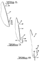
- FIG. 6 shows windowpane 14 in an ascended or closed position.
- windowpane 14 pivots at its transverse roofline edge 80, allowing beltline edge 82 of windowpane 14 to move laterally or transversely inwardly (hereinafter referred to as a "camming" action), toward the passenger compartment.
- beltline transverse edge 82 of windowpane 14 has moved inward sufficiently to clear the beltline edge 84 of the vehicle door 86, windowpane 14 can begin its decent into a window tracking channel (not shown in the Figures) within the door, as shown in Figure 8.
- transverse roofline edge 80 of windowpane 14 must be held relatively stable in place provide a pivot point for the windowpane's inward movement at the beltline.
- the window sealing mechanism at the lateral edges of windowpane 14 must allow for the lateral or transverse movement of the windowpane 14 at its transverse beltline edge 82 so that the camming action for the opening of the window is not impeded.
- the sealing strip stop short of full compression or, if structurally tapered, short of a full taper, i.e. retaining some bellows in side walls 54, 56 at the roofline portion, in order to maintain good contact between seal surfaces.
- the relatively increased compressibility of the body portion of the sealing strip as it approaches beltline 18 results in a window seal assembly which does not offer undue compressive resistance to such movement of the windowpane's transverse beltline edge 82.
- the camming action required for full flush window movement is not impeded by the window seal assembly used in the present invention.
- a further feature of the window seal assembly used in the present invention is the tear-away action of the magnetic seal.
- tear-away action is particularly advantageous in frameless window systems in which the window is directly sealed to the automotive vehicle body and opening of the door requires the breaking of the magnetic seal.
- the sealing strip used in the present invention has a tapered configuration, with the body portion being less compressed at the beltline than at the roofline.
- the seal will naturally first break-away from beltline portion, and tear or peel away from the beltline to the roofline, allowing the door to be opened with ease.
- This offers an advantage over conventional magnetic seals utilizing sealing members which are uniformly configured in sealing engagement, since the require breaking of the magnetic seal at all points simultaneously.
- the tear-away action is less pronounced but is offset by the decrease in length of engagement of the magnetic seal.
- window seal assembly used in the present invention is herein described as directed toward automotive side windows located between the vehicle's roofline and beltline, the window seal assembly used in the present invention is not limited to automotive side windows.
- the window seal assembly used in the invention can be employed in a variety of vehicle window openings, wherever any of its features as described herein would be desirable.
- the window seal assembly can be used for vehicle "moonroofs", truck windows, locomotive windows or the like.
Landscapes
- Engineering & Computer Science (AREA)
- Mechanical Engineering (AREA)
- Seal Device For Vehicle (AREA)
- Window Of Vehicle (AREA)
- Specific Sealing Or Ventilating Devices For Doors And Windows (AREA)
Claims (14)
- Fenstereinrichtung (10, 110) für ein Automobil (V) mit:(a) einer rahmenlosen, bewegbaren Fensterscheibe (14),(b) einer Fensteröffnung (12), deren Öffnung durch benachbarte Gehäuseplatten des Fahrzeuges (V) definiert ist und die durch die Fensterscheibe (14) geöffnet und geschlossen wird, und(c) einer Dichtungseinrichtung (10, 110), die der Abdichtung der Fensterscheibe (14) dient, wenn diese in der geschlossenen Position ist, wobei die Kanten der Fensterscheibe bündig mit den benachbarten Gehäuseplatten des Fahrzeuges (V) abschließen und wobei die Dichtungseinrichtung (10, 110):wobei die Fenstereinrichtung dadurch gekennzeichnet ist, daß:(i) einen länglichen, flexiblen Dichtungsstreifen (44, 144) aufweist, der ein erstes und ein zweites Ende hat sowie einen zusammenpreßbaren Körperabschnitt (46) und einen Befestigungsabschnitt (48, 148) für die Befestigung des Dichtungsstreifens (44, 144) entweder an einer der benachbarten Gehäuseplatten des Fahrzeuges (V) oder an einem Kantenabschnitt der Fensterscheibe (14);(ii) ein erstes Magnetelement (70, 170), das an dem Körperabschnitt (46) befestigt ist; und(iii) ein zweites Magnetelement (72, 172), das entweder an dem Kantenabschnitt der Fensterscheibe (14) oder an der einen benachbarten Gehäuseplatte des Fahrzeuges (V) befestigt ist und zwar daran, was nicht von dem Befestigungsabschnitt (48, 148) besetzt ist;
der Körperabschnitt (46) des Dichtungsstreifens (44, 144) der Dichtungseinrichtung (10, 110) ein länglicher, röhrenförmiger, hohler Abschnitt ist, der seitlich zusammenpreßbar ist,
und daß:
bei geschlossener Position der Fensterscheibe (14) die Kanten der Fensterscheibe (14) bündig mit den benachbarten Gehäuseplatten des Fahrzeuges (V) sind und die Fensterdichtungseinrichtung (10, 110) in wirksamen Dichtungseingriff mit der Fensterscheibe (14) steht, der Körperabschnitt (46) eine konische Gestalt hat und der zusammenpreßbare Körperabschnitt (46) von dem ersten Ende des Dichtungsstreifens (44, 144) zu dem zweiten Ende des Dichtungsstreifens (44, 144) in der Breite abnimmt. - Fenstereinrichtung nach Anspruch 1, worin der Befestigungsabschnitt (48) der Dichtungseinrichtung (10) an dem Fahrzeug (V) befestigt ist und das zweite Magnetelement (72) einem Kantenabschnitt (28) der Fensterscheibe (14) zugeordnet ist oder einen Teil davon bildet.
- Fenstereinrichtung nach Anspruch 1, worin der Befestigungsabschnitt (148) der Dichtungseinrichtung (110) an einem Kantenabschnitt (28) der Fensterscheibe (14) befestigt ist und das zweite Magnetelement (172) dem Fahrzeug (V) zugeordnet ist oder einen Teil davon bildet.
- Fenstereinrichtung nach Anspruch 3, worin das zweite Magnetelement (172) der Dichtungseinrichtung (110) von dem Fahrzeug (V) gebildet wird, das gemäß seiner Natur eisenhaltig ist.
- Fenstereinrichtung nach einem der Ansprüche 1 bis 4, worin der Dichtungsstreifen (44, 144) der Dichtungseinrichtung (10, 110) baulich verjüngt ist.
- Fenstereinrichtung nach einem der vorangehenden Ansprüche, worin wenigstens ein Magnetelement (70, 170, 72, 172) der Dichtungseinrichtung (10, 110) ein Dauermagnet ist.
- Fenstereinrichtung nach einem der vorangehenden Ansprüche, worin wenigstens ein Magnetelement (70, 170, 72, 172) der Dichtungseinrichtung (10, 110) ein Eisenmetall ist.
- Fenstereinrichtung nach Anspruch 1, worin der zusammendrückbare Körperabschnitt (46) der Dichtungseinrichtung (10) eine gemeinsame Wand (50), eine äußere Wand (52) und sich dazwischen erstreckende Seitenwände (54, 56) aufweist, wobei die Wände (50, 52, 54, 56) einen hohlen Innenraum (58) in dem Körperabschnitt (46) definieren;
der Befestigungsabschnitt (48) der Dichtungseinrichtung (10) sich für die Befestigung des Dichtungsstreifens (44) an einer der benachbarten Gehäuseplatten des Fahrzeuges (V) von der gemeinsamen Wand (50) erstreckt und sich diese Wand mit dem Körperabschnitt (46) teilt;
das erste Magnetelement (70) der Dichtungseinrichtung (10) in der äußeren Wand (52) des Körperabschnitts (46) eingebettet ist; und
das zweite Magnetelement (72) der Dichtungseinrichtung (10, 110) komplementär zu dem ersten Magnetelement (70) ist und an einer seitlichen Kante (28) der Fensterscheibe (14) für einen zusammenwirkenden Eingriff mit dem ersten Magnetelement (70) befestigt ist. - Fenstereinrichtung nach Anspruch 8, worin das erste Magnetelement (70) der Dichtungseinrichtung (10) ein flexibler elastomerer Magnet ist.
- Fenstereinrichtung nach Anspruch 8 oder 9, worin
die Seitenwände (54, 56) in der Dichtungseinrichtung (10) gefaltet sind
und worin
bei geschlossener Position der Fensterscheibe (14) der Dichtungsstreifen (44) durch die selektive Kompression des Körperabschnitts (46) entlang der Länge des Dichtungsstreifens (44) aufgrund des Zusammendrückens verjüngt vorliegt, wodurch veranlaßt wird, daß wenigstens ein Abschnitt der gefalteten Seitenwände (54, 56) sich in einer Akkordeon-ähnlichen Weise zusammendrückt. - Fenstereinrichtung nach einem der Ansprüche 8 bis 10, wobei die Dichtungseinrichtung (10) ferner eine keramische Schicht (74) an der seitlichen Kante (28) der Fensterscheibe (14) aufweist und das zweite Magnetelement (72) mit der keramischen Schicht (74) verbunden ist.
- Fenstereinrichtung nach einem der vorangehenden Ansprüche, worin der Dichtungsstreifen (44) der Dichtungseinrichtung (10, 110) aus Gummi besteht.
- Fenstereinrichtung nach Anspruch 9, worin die Fensterscheibe (14) zwischen der Gürtellinie (18) und der Dachlinie (16) des Fahrzeuges (V) und vor der B-Säule (22) des Fahrzeuges (V) angeordnet ist und worin
der Befestigungsabschnitt (48) der Dichtungseinrichtung (10, 110) ein U-förmiger Befestigungsabschnitt (48) ist, um den Dichtungsstreifen (44) an den benachbarten Seitenplatten des Fahrzeuges (V) zu befestigen, wobei der U-förmige Befestigungsabschnitt (48) einen U-förmigen Kanal (64) definiert und der Befestigungsabschnitt (48) Greifrippen (66) aufweist, die sich in den U-förmigen Kanal (64) erstrecken;
und worin
der U-förmige Befestigungsabschnitt (48) der Dichtungseinrichtung (10, 110) an einer Seitenkante der B-Säule (22) befestigt ist, die benachbart zu der Seitenkante (28) der Fensterscheibe (14) angeordnet ist;
und worin
der Dichtungsstreifen (44) der Dichtungseinrichtung aufgrund des Zusammendrückens konisch ausgebildet ist, wenn der Dichtungsstreifen in Dichtungseingriff mit den benachbarten Gehäuseplatten des Fahrzeuges (V) und der Fensterscheibe (14) steht, wobei der Dichtungsstreifen (44) an der Gürtellinie (18) weniger stark zusammengedrückt ist als an der Dachlinie (16) des Fahrzeuges (V). - Fenstereinrichtung nach Anspruch 13, worin die Fensterscheibe (14) durch einen Nockenmechanismus bewegt wird.
Applications Claiming Priority (2)
| Application Number | Priority Date | Filing Date | Title |
|---|---|---|---|
| US27248488A | 1988-11-16 | 1988-11-16 | |
| US272484 | 1988-11-16 |
Publications (3)
| Publication Number | Publication Date |
|---|---|
| EP0369799A2 EP0369799A2 (de) | 1990-05-23 |
| EP0369799A3 EP0369799A3 (en) | 1990-12-27 |
| EP0369799B1 true EP0369799B1 (de) | 1994-02-09 |
Family
ID=23039995
Family Applications (1)
| Application Number | Title | Priority Date | Filing Date |
|---|---|---|---|
| EP89311900A Expired - Lifetime EP0369799B1 (de) | 1988-11-16 | 1989-11-16 | Magnetische Fensterscheibendichtung |
Country Status (6)
| Country | Link |
|---|---|
| EP (1) | EP0369799B1 (de) |
| JP (1) | JP2860566B2 (de) |
| KR (1) | KR900007641A (de) |
| AU (1) | AU637771B2 (de) |
| CA (1) | CA1326874C (de) |
| DE (1) | DE68913009T2 (de) |
Families Citing this family (22)
| Publication number | Priority date | Publication date | Assignee | Title |
|---|---|---|---|---|
| CA2002151A1 (en) * | 1989-05-11 | 1990-11-11 | Scott E. Baker | Magnetic seal |
| IT1248065B (it) * | 1991-06-17 | 1995-01-05 | Ilpea Ind Spa | Guarnizione magnetica adatta in particolare ad effettuare una tenuta tra una parte fissa, quale ad esempio la scocca di un autoveicolo, ed una parte apribile, quale ad esempio la portiera, nelle zone ad andamento curvilineo. |
| FR2724600B1 (fr) * | 1994-09-20 | 1997-04-18 | Peugeot | Agencement de maintien d'une vitre d'une porte d'un vehicule automobile sur la caisse de celui-ci |
| IT1284803B1 (it) * | 1996-09-19 | 1998-05-22 | Fiat Auto Spa | Sistema di copertura di parte del telaio della portiera di un autoveicolo |
| GB9711357D0 (en) * | 1997-06-02 | 1997-07-30 | Hobby Peter | Flexible strip |
| IT247920Y1 (it) * | 1999-03-09 | 2002-09-16 | Italdesign Spa | Sistema servo-assistito per l'apertura e la chiusura di vetri lateralidi un'autovettura. |
| GB2348232B (en) * | 1999-03-25 | 2003-10-01 | Draftex Ind Ltd | Sealing,trimming and finishing strips |
| DE10040919A1 (de) * | 2000-08-18 | 2002-03-07 | Webasto Vehicle Sys Int Gmbh | Dichtung für Fahrzeugdächer |
| FR2813244B1 (fr) * | 2000-08-28 | 2003-03-07 | Renault | Ouvrant de vehicule automobile comportant un joint aimante |
| US20050198904A1 (en) * | 2004-03-12 | 2005-09-15 | Browne Alan L. | Active seal assemblies for movable windows |
| KR100551802B1 (ko) * | 2004-05-13 | 2006-02-13 | 기아자동차주식회사 | 자동차용 도어 윈도우의 소음 방지 방법 및 장치 |
| JP5091405B2 (ja) * | 2005-12-28 | 2012-12-05 | 有限会社ヤマヱ | 液体浄化装置 |
| CA2650843C (en) * | 2006-05-05 | 2013-05-21 | Grant W. Crider | Portal covering for controlled environments |
| DE202006008136U1 (de) * | 2006-05-19 | 2006-07-20 | Rehau Ag + Co | Dichtungsprofil mit Magnet |
| DE102009035561A1 (de) * | 2009-07-31 | 2011-02-03 | Aktiebolaget Skf | Dichtungsanordnung zur Abdichtung eines Spalts und Stromversorgungsanordnung |
| FR2978517B1 (fr) * | 2011-07-29 | 2014-05-30 | Jpr | Joint de connexion entre deux structures mobiles entre elles. |
| CN102642310B (zh) * | 2012-05-09 | 2014-05-07 | 安徽万朗磁塑集团有限公司 | 全自动冰箱门密封条生产线 |
| US10718435B2 (en) * | 2018-03-12 | 2020-07-21 | Gdc, Inc. | Compressible seal for sealing an interface between a recreational vehicle slide out and a recreational vehicle frame |
| CN111422046B (zh) * | 2020-04-22 | 2022-03-25 | 东风汽车集团有限公司 | 一种磁力式玻璃导槽密封条及密封系统 |
| CN115709636B (zh) * | 2022-11-16 | 2026-01-02 | 北京海纳川汽车部件股份有限公司 | 无框车门玻璃密封结构和具有其的车辆 |
| CN116039352B (zh) * | 2023-01-29 | 2026-01-02 | 奇瑞汽车股份有限公司 | 一种车用可除雨水外水切密封装置及控制方法 |
| FR3155746B1 (fr) * | 2023-11-24 | 2025-11-28 | Saint Gobain | Vitrage de vehicule a support aimante |
Family Cites Families (4)
| Publication number | Priority date | Publication date | Assignee | Title |
|---|---|---|---|---|
| JPS55120517U (de) * | 1979-02-20 | 1980-08-26 | ||
| FR2544372B1 (fr) * | 1982-11-08 | 1985-11-08 | Mesnel Sa Ets | Glaces mobiles " affleurantes ", par effet magnetique, notamment pour des portes d'automobiles |
| FR2555650B1 (fr) * | 1983-11-30 | 1987-07-10 | Laques Indochin Caoutchouc Ind | Dispositif d'etancheite pour panneau mobile, notamment vitre laterale d'automobile |
| JPS61165818U (de) * | 1985-04-04 | 1986-10-15 |
-
1989
- 1989-08-14 CA CA000608237A patent/CA1326874C/en not_active Expired - Fee Related
- 1989-10-18 AU AU43515/89A patent/AU637771B2/en not_active Ceased
- 1989-11-02 JP JP1287309A patent/JP2860566B2/ja not_active Expired - Fee Related
- 1989-11-15 KR KR1019890016656A patent/KR900007641A/ko not_active Withdrawn
- 1989-11-16 DE DE68913009T patent/DE68913009T2/de not_active Expired - Fee Related
- 1989-11-16 EP EP89311900A patent/EP0369799B1/de not_active Expired - Lifetime
Also Published As
| Publication number | Publication date |
|---|---|
| AU4351589A (en) | 1990-05-24 |
| KR900007641A (ko) | 1990-06-01 |
| EP0369799A2 (de) | 1990-05-23 |
| EP0369799A3 (en) | 1990-12-27 |
| DE68913009D1 (de) | 1994-03-24 |
| AU637771B2 (en) | 1993-06-10 |
| JPH02175429A (ja) | 1990-07-06 |
| JP2860566B2 (ja) | 1999-02-24 |
| DE68913009T2 (de) | 1994-05-19 |
| CA1326874C (en) | 1994-02-08 |
Similar Documents
| Publication | Publication Date | Title |
|---|---|---|
| US4999951A (en) | Magnetic window seal assembly | |
| EP0369799A2 (de) | Magnetische Fensterscheibendichtung | |
| US5355628A (en) | Weatherstrip for a vehicle door | |
| US5038521A (en) | Sealing strips | |
| EP1232887B1 (de) | Türzarge für Kraftfahrzeuge | |
| US5345717A (en) | Window construction for vehicles | |
| US6691464B2 (en) | Vertical slider window assembly | |
| EP0612638B1 (de) | Scheibenausbildung mit vier aufliegenden Rändern | |
| US5027556A (en) | Window sealing and guiding arrangements | |
| JP2816405B2 (ja) | 自動車のフレーム構造とフレーム製作法 | |
| EP0599538A1 (de) | Fensterschachtdichtung | |
| EP0783988B1 (de) | Dichtungsstreifen für Kraftfahrzeuge | |
| EP0376450A2 (de) | Dichtungssystem für ein Fenster mit verschiebbarer Doppelscheibe | |
| EP0684158A1 (de) | Verformbare Dichtung für beweglichen Fensterscheiben | |
| EP0739770A1 (de) | Abdichtungssystem mit vier aufliegenden Rändern | |
| EP0436298B1 (de) | Dichtung für Kraftfahrzeugtür | |
| EP0521611B1 (de) | Türdichtung | |
| US5367831A (en) | Flush mount magnetic header seal | |
| US20040134132A1 (en) | Sealing and guiding strips | |
| US4581851A (en) | Window arrangement having a pane which is adjustable in height, particularly for motor vehicles | |
| JPS633284Y2 (de) | ||
| US6748638B2 (en) | Apparatus and method for locating a vehicle window panel | |
| JPH07223437A (ja) | ウエザーストリップの取付構造 | |
| EP0747265A1 (de) | Befestigungs-, Dichtungs- oder Zierstreifen | |
| GB2086459A (en) | Improvements in and relating to sealing strips |
Legal Events
| Date | Code | Title | Description |
|---|---|---|---|
| PUAI | Public reference made under article 153(3) epc to a published international application that has entered the european phase |
Free format text: ORIGINAL CODE: 0009012 |
|
| AK | Designated contracting states |
Kind code of ref document: A2 Designated state(s): DE FR GB |
|
| PUAL | Search report despatched |
Free format text: ORIGINAL CODE: 0009013 |
|
| AK | Designated contracting states |
Kind code of ref document: A3 Designated state(s): DE FR GB |
|
| 17P | Request for examination filed |
Effective date: 19901228 |
|
| 17Q | First examination report despatched |
Effective date: 19920124 |
|
| GRAA | (expected) grant |
Free format text: ORIGINAL CODE: 0009210 |
|
| AK | Designated contracting states |
Kind code of ref document: B1 Designated state(s): DE FR GB |
|
| REF | Corresponds to: |
Ref document number: 68913009 Country of ref document: DE Date of ref document: 19940324 |
|
| ET | Fr: translation filed | ||
| PLBE | No opposition filed within time limit |
Free format text: ORIGINAL CODE: 0009261 |
|
| STAA | Information on the status of an ep patent application or granted ep patent |
Free format text: STATUS: NO OPPOSITION FILED WITHIN TIME LIMIT |
|
| 26N | No opposition filed | ||
| PGFP | Annual fee paid to national office [announced via postgrant information from national office to epo] |
Ref country code: DE Payment date: 20001124 Year of fee payment: 12 |
|
| REG | Reference to a national code |
Ref country code: GB Ref legal event code: IF02 |
|
| PG25 | Lapsed in a contracting state [announced via postgrant information from national office to epo] |
Ref country code: DE Free format text: LAPSE BECAUSE OF NON-PAYMENT OF DUE FEES Effective date: 20020702 |
|
| PGFP | Annual fee paid to national office [announced via postgrant information from national office to epo] |
Ref country code: GB Payment date: 20041207 Year of fee payment: 16 |
|
| PGFP | Annual fee paid to national office [announced via postgrant information from national office to epo] |
Ref country code: FR Payment date: 20041222 Year of fee payment: 16 |
|
| REG | Reference to a national code |
Ref country code: FR Ref legal event code: CD |
|
| PG25 | Lapsed in a contracting state [announced via postgrant information from national office to epo] |
Ref country code: GB Free format text: LAPSE BECAUSE OF NON-PAYMENT OF DUE FEES Effective date: 20051116 |
|
| GBPC | Gb: european patent ceased through non-payment of renewal fee |
Effective date: 20051116 |
|
| PG25 | Lapsed in a contracting state [announced via postgrant information from national office to epo] |
Ref country code: FR Free format text: LAPSE BECAUSE OF NON-PAYMENT OF DUE FEES Effective date: 20060731 |
|
| REG | Reference to a national code |
Ref country code: FR Ref legal event code: ST Effective date: 20060731 |