EP0369827A1 - Production et utilisation d'un agent de refroidissement dans des dispositif cryogéniques - Google Patents
Production et utilisation d'un agent de refroidissement dans des dispositif cryogéniques Download PDFInfo
- Publication number
- EP0369827A1 EP0369827A1 EP89311971A EP89311971A EP0369827A1 EP 0369827 A1 EP0369827 A1 EP 0369827A1 EP 89311971 A EP89311971 A EP 89311971A EP 89311971 A EP89311971 A EP 89311971A EP 0369827 A1 EP0369827 A1 EP 0369827A1
- Authority
- EP
- European Patent Office
- Prior art keywords
- cryostat
- fluorocarbon
- liquid nitrogen
- cooling medium
- coolant
- Prior art date
- Legal status (The legal status is an assumption and is not a legal conclusion. Google has not performed a legal analysis and makes no representation as to the accuracy of the status listed.)
- Granted
Links
Images



Classifications
-
- C—CHEMISTRY; METALLURGY
- C09—DYES; PAINTS; POLISHES; NATURAL RESINS; ADHESIVES; COMPOSITIONS NOT OTHERWISE PROVIDED FOR; APPLICATIONS OF MATERIALS NOT OTHERWISE PROVIDED FOR
- C09K—MATERIALS FOR MISCELLANEOUS APPLICATIONS, NOT PROVIDED FOR ELSEWHERE
- C09K5/00—Heat-transfer, heat-exchange or heat-storage materials, e.g. refrigerants; Materials for the production of heat or cold by chemical reactions other than by combustion
- C09K5/02—Materials undergoing a change of physical state when used
- C09K5/04—Materials undergoing a change of physical state when used the change of state being from liquid to vapour or vice versa
- C09K5/041—Materials undergoing a change of physical state when used the change of state being from liquid to vapour or vice versa for compression-type refrigeration systems
- C09K5/044—Materials undergoing a change of physical state when used the change of state being from liquid to vapour or vice versa for compression-type refrigeration systems comprising halogenated compounds
- C09K5/045—Materials undergoing a change of physical state when used the change of state being from liquid to vapour or vice versa for compression-type refrigeration systems comprising halogenated compounds containing only fluorine as halogen
-
- C—CHEMISTRY; METALLURGY
- C09—DYES; PAINTS; POLISHES; NATURAL RESINS; ADHESIVES; COMPOSITIONS NOT OTHERWISE PROVIDED FOR; APPLICATIONS OF MATERIALS NOT OTHERWISE PROVIDED FOR
- C09K—MATERIALS FOR MISCELLANEOUS APPLICATIONS, NOT PROVIDED FOR ELSEWHERE
- C09K5/00—Heat-transfer, heat-exchange or heat-storage materials, e.g. refrigerants; Materials for the production of heat or cold by chemical reactions other than by combustion
- C09K5/02—Materials undergoing a change of physical state when used
- C09K5/04—Materials undergoing a change of physical state when used the change of state being from liquid to vapour or vice versa
-
- H—ELECTRICITY
- H10—SEMICONDUCTOR DEVICES; ELECTRIC SOLID-STATE DEVICES NOT OTHERWISE PROVIDED FOR
- H10W—GENERIC PACKAGES, INTERCONNECTIONS, CONNECTORS OR OTHER CONSTRUCTIONAL DETAILS OF DEVICES COVERED BY CLASS H10
- H10W40/00—Arrangements for thermal protection or thermal control
- H10W40/30—Arrangements for thermal protection or thermal control wherein the packaged device is completely immersed in a fluid other than air, e.g. immersed in a cryogenic fluid
- H10W40/305—Arrangements for thermal protection or thermal control wherein the packaged device is completely immersed in a fluid other than air, e.g. immersed in a cryogenic fluid the fluid being a liquefied gas, e.g. liquid nitrogen
-
- C—CHEMISTRY; METALLURGY
- C09—DYES; PAINTS; POLISHES; NATURAL RESINS; ADHESIVES; COMPOSITIONS NOT OTHERWISE PROVIDED FOR; APPLICATIONS OF MATERIALS NOT OTHERWISE PROVIDED FOR
- C09K—MATERIALS FOR MISCELLANEOUS APPLICATIONS, NOT PROVIDED FOR ELSEWHERE
- C09K2205/00—Aspects relating to compounds used in compression type refrigeration systems
- C09K2205/10—Components
- C09K2205/12—Hydrocarbons
- C09K2205/128—Perfluorinated hydrocarbons
-
- F—MECHANICAL ENGINEERING; LIGHTING; HEATING; WEAPONS; BLASTING
- F25—REFRIGERATION OR COOLING; COMBINED HEATING AND REFRIGERATION SYSTEMS; HEAT PUMP SYSTEMS; MANUFACTURE OR STORAGE OF ICE; LIQUEFACTION SOLIDIFICATION OF GASES
- F25D—REFRIGERATORS; COLD ROOMS; ICE-BOXES; COOLING OR FREEZING APPARATUS NOT OTHERWISE PROVIDED FOR
- F25D3/00—Devices using other cold materials; Devices using cold-storage bodies
- F25D3/10—Devices using other cold materials; Devices using cold-storage bodies using liquefied gases, e.g. liquid air
Definitions
- the present invention relates to a coolant having a high cooling capability for use in cryogenic devices.
- the coolant is particularly suitable as a cooling medium or a heat exchange medium when semiconductor devices such as those which can exhibit a high speed switching at a cryogenic temperature of about 123 K or less, such as 77.3 K, i.e,, a boiling point of liquid nitrogen (LN2), or other devices such as those using a superconducting material are cooled to a working temperature thereof.
- a cryogenic temperature of about 123 K or less, such as 77.3 K, i.e, a boiling point of liquid nitrogen (LN2), or other devices such as those using a superconducting material are cooled to a working temperature thereof.
- LN2 boiling point of liquid nitrogen
- any cryogenic temperature around the boiling point of liquid nitrogen is referred to herein as a liquid nitrogen temperature.
- the present invention also relates to a method for the production of the coolant, a method of cooling an, article to the cryogenic temperature,
- the mobility of a carrier in the semiconductor can be increased by reduction of a temperature to which the semiconductor is subjected, and based on this temperature characteristic, high speed switching devices which are operable at the liquid nitrogen temperature, such as high electron mobility transistors (HEMTs) or complementary metal oxide semiconductor (CMOS) devices, have been developed.
- HEMTs high electron mobility transistors
- CMOS complementary metal oxide semiconductor
- the latter cooling method based on the boiling heat transfer can be advantageously used when the devices to be cooled have a large heat generation density and a complex structure or configuration.
- this cooling method can be applied to the cooling of central processing units (CPUs) of a computer.
- CPUs central processing units
- Suitable liquefied gases having a stable and simple composition are liquefied nitrogen, described above, and liquefied helium. Liquefied nitrogen is obtained by liquefying air and separating the resulting fluid.
- cryogenic fluid Use of liquefied nitrogen as the cryogenic fluid is described in, for example, F.H. Gaensslen, V.L. Rideout, E. J. Walker and J.J. Walker, "Very Small MOSFET's for Low-Temperature Operation", IEEE TRANSACTIONS ON ELECTRON DEVICES, MARCH 1977, in which FET's are cooled by direct immersion in an open pool of the liquefied nitrogen.
- liquefied fluorocarbons as the cryogenic fluid is described in, for example, "Cooling a Superfast Computer", ELECTRONIC PACKAGING & PRODUCTION, JULY 1986, in which the entire computer is immersed in a non-conductive circular fluorocarbon liquid.
- cryogenic fluid a mixture of liquefied nitrogen and liquefied fluorocarbon (CF4) as the cryogenic fluid is described in, for example, T. Amano and M. Nagao, "Boiling Heat transfer Characteristics of Mixed Coolant", 1988 Cryogenic Society of Japan Spring Meeting, C1-4, May 1988, in which a superconducting material having a high Tc is directly immersed in a mixed coolant consisting of the liquefied nitrogen and liquefied CF4 in an open can.
- CF4 liquefied fluorocarbon
- thermocoupler 4 as a temperature sensor connected with a recorder 8 is also disposed in the mixed coolant 2.
- 5 is a balance-scale used to determine a change of the weight of the coolant 2
- 6 is a DC supply
- 7 is a resistor.
- the mixed coolant in a closed system has been considered, but since the mixed coolant must contain a higher amount of the liquefied CF4, i.e., as high as 8 to 20% by moles, the composition of the mixed coolant will be changed upon liquefaction of the vaporized coolant, thereby causing variations in the cooling capability of the coolant. Further, in the vaporized coolant, the high boiling components thereof tend to be condensed and separated in a liquefied or refrigerator used to again liquefy the vaporized coolant, because of a high concentration of the high boiling components. The separated components will cause clogging of the pipes, stoppage of the apparatus and other unavoidable drawbacks.
- An object of the present invention is to provide a novel coolant for use in cryogenic devices using a closed cycle or loop system.
- the coolant should exhibit an increased cooling capability, and also should not have the problem of the prior art as described above.
- a coolant for use in a cryogenic device having a closed cycle system, which comprises a mixture of a liquid nitrogen and a fluorocarbon of the formula: CnF 2n+2 , wherein n is an integer of 2 to 4.
- a method of producing a coolant comprising a mixture of a liquid nitrogen and a fluorocarbon of the formula: CnF 2n+2 , wherein n is an integer of 2 to 4, which method comprises the step of cooling a mixed gas of nitrogen and fluorocarbon of the formula: CnF 2n+2 , wherein n is as defined above, under pressure to liquefy the mixed gas.
- a method of producing a coolant comprising a mixture of a liquid nitrogen and a fluorocarbon of the formula: CnF 2n+2 , wherein n is an integer of 2 to 4, which method comprises the step of introducing a gaseous fluorocarbon of the formula: CnF 2n+2 , wherein n is as defined above, into a liquid nitrogen to obtain the liquid nitrogen having the fluorocarbon dissolved therein.
- a method of cooling an article to a cryogenic temperature of 123K or less comprises the step of immersing the article in a coolant which comprises a mixture of a liquid nitrogen and a fluorocarbon of the formula: C n F 2n+2 , wherein n is an integer of 2 to 4.
- a cryogenic device in a closed cycle system which comprises a closed cryostat containing, as a cooling medium, a mixture of a liquid nitrogen and a fluorocarbon of the formula: C n F 2n+2 , wherein n is an integer of 2 to 4, an article to be cooled being immersed in the cooling medium in the cryostat, and cooled to a cryogenic temperature of 123K or less.
- a cryogenic device having a closed cycle system, which comprises a closed cryostat containing, as a cooling medium, one or more liquid fluorocarbons of the formula: Cm F 2m+2 , wherein m is an integer of 1 to 4, an article to be cooled being immersed in the cooling medium, and a heat exchanger pipe which is disposed in an upper inner portion of the cryostat and is communicated with a separate liquifier, so that the cooling medium boiled and vaporized as a result of a heat generation in the cryostat is liquified within the same cryostat as a result of a heat exchange between a vapor of the cooling medium and a liquified gas circulated as a heat exchange medium in the heat exchanger pipe.
- an unexpectedly increased cooling capability can be obtained with the use of a small amount of the fluorocarbon in the liquefied nitrogen.
- about twice the cooling capability can be obtained in the present invention, without a separation of high boiling points in a liquefier and other prior art drawbacks.
- a coolant according to the present invention comprises a mixture of liquid nitrogen and a fluorocarbon CnF 2n+2 , wherein n is as defined above.
- the coolant comprises liquid nitrogen having the fluorocarbon dissolved therein.
- the fluorocarbon used is C2F6 , C3F8 , C4F10 or a mixture thereof.
- the use of CF4 must be avoided because as described above, it must be added in a remarkably increased amount to the liquid nitrogen, and thus produces drawbacks originating from such an addition of CF4.
- the use of C n F 2n+2 wherein n is 5 or more must be also avoided, because such fluorocarbons having a higher number of carbon atoms have an increased boiling point, and can solidify when mixed with the liquid nitrogen.
- a smaller amount of the fluorocarbon is generally added to the liquid nitrogen, in comparison with the prior art coolant in which the fluorocarbon or CF4 is added in an amount of about 8 to 20% by moles or more to the liquid nitrogen, to obtain a satisfactory cooling capability of the order of about 40 W/cm2.
- C2F6 an increase of the cooling capability begins at a concentration of 0.1% by mole and a maximum cooling capability is obtained at a concentration of 0.5% by mole.
- a saturated cooling capability is obtained at a concentration of more than 0.5% by mole.
- C2F6 is added in an amount of more than 3% by mole, the resultant coolant is clouded and has a reduced saturated cooling capability. Similar cooling characteristics can be observed for other fluorocarbons C3F8 and C4F10 except that an increased cooling capability can be obtained by an addition of an amount of 0.1 to 0.5% by mole for C and of 0.1 to 0.3% by mole for C4F10.
- the coolant according to the present invention can be advantageously produced in accordance with the following methods.
- One production method comprises the step of cooling a mixed gas of nitrogen and fluorocarbon of the formula: C n F 2n+2 , wherein n is as defined above, under pressure to liquefy the mixed gas.
- the ratio of fluorocarbon to nitrogen in the mixed gas is substantially the same as that of the resultant coolant, and an increased pressure of 1 to 2 atms is applied to the mixed gas during the cooling step, and further the mixed gas in a high pressure vessel is introduced into a liquefier where the gas is cooled with a compressed and adiabatically cooled gas.
- a second production method comprises the step of introducing a gaseous fluorocarbon of the formula: C n F 2n+2 , wherein n is as defined above, into a liquid nitrogen to obtain the liquid nitrogen having the fluorocarbon dissolved therein.
- a gaseous fluorocarbon of the formula: C n F 2n+2 wherein n is as defined above
- the gaseous fluorocarbon in a high pressure vessel is introduced into the liquid nitrogen in a Dewar's vessel, and further the gaseous fluorocarbon from the high pressure vessel is passed through the liquid nitrogen in another Dewar's vessel before an introduction thereof into the liquid nitrogen, to cool the gaseous fluorocarbon to a temperature beyond which the fluorocarbon is liquefied.
- the article is immersed in the coolant consisting of the liquid nitrogen and fluorocarbon as described above.
- the coolant is placed as a cooling medium in a closed cryostat of the cryogenic device.
- the cooling medium boiled and vaporized in the cryostat is preferably liquefied in a separate liquefier, and the thus produced cooling medium in the form of a liquid is returned to the cryostat.
- the cooling medium boiled and vaporized in the cryostat is liquefied within the same cryostat as a result of heat exchange between a vapor of the cooling medium and a heat exchange medium in a heat exchanger pipe disposed at a suitable position in the cryostat so that the heat exchange is made therein.
- the heat exchange medium circulated through the heat exchanger pipe is preferably a liquid nitrogen.
- other heat exchange media may be circulated, if desired.
- a wall of the cryostat is preferably provided with inlet and outlet openings communicated through pipes with a separate liquefier, so that the cooling medium boiled and vaporized as a result of heat generation of the article in the cryostat is guided into and liquefied in the liquefier, and the thus produced cooling medium in the form of a liquid is returned to the cryostat.
- an upper inner portion of the cryostat has a heat exchanger pipe disposed at a suitable position therein and communicated with a separate liquefier, so that the cooling medium boiled and vaporized as a result of heat generation in the cryostat is liquefied within the same cryostat, as a result of a heat exchange between vapor of the cooling medium and a heat exchange medium in the heat exchanger pipe.
- the liquefier used in the present invention may have any conventional structure, but preferably the liquefier comprises a Stirling cycle refrigerator with a compressor.
- any heat exchange medium may be used in the practice of the present invention, but to obtain a satisfactory heat exchange effect, it is necessary to circulate a heat exchange medium having a lower boiling point than that of the cooling medium used simultaneously in the cryostat, through the heat exchanger pipe of the liquefier. If the above requirements are satisfied, a heat transfer by boiling occurs at the portion of the heat exchanger pipe, and thus a higher efficiency heat transfer, compared with that of the convection heat transfer obtained by using a helium gas in the heat exchanger pipe, is ensured.
- the coolant of the present invention is preferably used as the cooling medium in the cryostat, and the liquid nitrogen as the heat exchange medium in the heat exchanger pipe.
- the present invention can be applied to the cooling of any articles which are to be cooled to a cryogenic temperature of 123 K or less.
- Typical examples of such articles are semiconductor devices such as high electron mobility transistors or complementary metal oxide semiconductor devices, devices using a superconducting material which exhibits a superconductivity at the cryogenic temperature, or electronic equipment which is operable at the cryogenic temperature.
- semiconductor devices such as high electron mobility transistors or complementary metal oxide semiconductor devices
- devices using a superconducting material which exhibits a superconductivity at the cryogenic temperature or electronic equipment which is operable at the cryogenic temperature.
- large-scale computers can be cooled, with a high efficiency, in a cryogenic device having a simple structure.
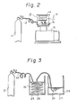
- a coolant was prepared by using a liquefier 13 which consists of a Stirling cycle refrigerator 14 and a high-pressure compressor 15.
- a mixed gas of nitrogen and fluorocarbon (C2F6 was used here ) was charged to a steel gas cylinder 11 and the gas was supplied through a conduit 12 to the refrigerator 14.
- the gas in a container 17 of the refrigerator 14 was cooled under an applied pressure of about 1.3 to 1.5 atm. to form the coolant, i.e., mixture of the liquid nitrogen (LN2) and C2F6 , 18.
- the gas was cooled by cooling a bottom portion of the container 17 with a cold head (not shown) of the refrigerator 14.
- a specific cooling gas having, for example, a temperature of about 70K, such as liquid helium of 11 to 13 kg/cm2 was compressed in the compressor 15, and the compressed gas was adiabatically cooled with a piston 16, and as a result of an indirect contact of the thus cooled gas in the cold head with the mixed gas from the gas cylinder 11, the coolant 18 was produced in the container 17.
- the coolant or liquefied gas of LN2 and C2F6 having a predetermined ratio of LN2 to C2F6 can be prepared with a good reproducibility and controllability, because such a ratio of LN2 to C2F6 is defined depending upon the specific composition of the mixed gas filled in the gas cylinder.
- a coolant was prepared by bubbling a gas of the fluorocarbon CnF 2n+2 (C2F6 was used here ) in a liquid nitrogen 28 in a Dewar vessel 27.
- the C2F6 gas was supplied through a conduit 22 to a cooling pipe 23 dipped in a liquid nitrogen 26 in a Dewar vessel 25, and after cooling, the cooled gas from the cooling pipe 23 was supplied through a conduit 24 to the vessel 27 and bubbled in the liquid nitrogen 28.
- the coolant i.e., mixture of the liquid nitrogen and C2F6, was prepared in the vessel 27.
- a mixing ratio of C2F6 in the resulting coolant could be freely controlled by suitably changing a pressure applied to the C2F6 gas in the gas cylinder and a flow rate of the C2F6 gas in the conduit 24.
- C2F6 was used as the fluorocarbon, but, it should be noted that similar satisfactory results can be obtained if C2F6 is replaced with a fluorocarbon C3F8 or C4F10 , or any combination of these fluorocarbons. Further, in the production of Fig. 3, the C2F6 gas in the cylinder 21 may additionally contain a nitrogen gas, if necessary.
- the coolant of the present invention is placed in a closed cryostat.
- the cooling using the cryostat will be described hereinafter with reference to Figs. 4 and 5. Note, a heat exchanger portion was omitted from Fig. 4, to simplify under standing of the present invention.
- a closed cryostat 33 was charged with the coolant or cooling medium 34 of the present invention.
- the cooling medium 34 used consists of the liquid nitrogen and fluorocarbon CF4 in an amount of 3.41% by mole relative to the total moles of the cooling medium.
- a circuit board 32 of 100 mm x 100 mm in size having 4 x 4 LSI chips 31 of 10 mm x 10 mm in size mounted thereon was dipped in the cooling medium 34. With an application of an electric voltage through an electric cable (not shown) to the LSI chips 31, the boiling of the cooling medium 34 begun and small bubbles 35 of the vapor of the medium 34 were generated on the surface of the heated LSI chips 31. The chips 31 were thus cooled as a result of removal of vaporization heat from the chip surface.
- the cooling capability of the used cooling medium was evaluated by defining it as the heat flux at the shift from nucleate boiling to layer or film boiling.
- the shift point was decided by measuring the relationship between the chip temperature and power dissipation.
- the chip temperature was measured at diodes formed on the chip surface.
- the results of this evaluation showed that the cooling capability per unit area of the LSI chip, at the point of the transition to the layer boiling state, is about 30 to 50 W/cm2, i.e., two to three times higher than that when the liquid nitrogen alone was used.
- the cooling capability of the pure liquid nitrogen under the same conditions was about 15 to 20 W/cm2.
- cryogenic cooling of the present invention was described above with reference to Fig. 4. More particu larly, the cryogenic cooling can be advantageously carried out by using a cryogenic device of Fig. 6 or Fig. 7.
- the cryogenic device of Fig. 6 was of the closed loop or cycle system which comprises a cryostat 33 and a liquefier 13.
- the liquefier 13, as have been described with reference to Fig. 2, consisted of a refrigerator 14 and a high-pressure compressor 15.
- a cooling medium 34 filled in the cryostat 33 was a mixture of the liquid nitrogen and 0.5% by mole of fluorocarbon (C2F6 was used here ).
- a circuit board 32 of 100 mm x 100 mm in size and having 4 x 4 LSI chips 31 of 10 mm x 10 mm in size mounted thereon was directly immersed in the cooling medium 34.
- the supply of an electric voltage to the chips 31 was made using a power cable (not shown) from an electric source, and boiling of the cooling medium 34 begun upon application of the electric voltage to the chips 31, whereby small bubbles 35 of the vapor of the medium 34 were generated on the surface of the heated chips 31.
- the chips 31 were thus cooled by the vaporization of heat therefrom.
- the vapor of the cooling medium thus produced was fed through a feed pipe 36 to a container 17 of the refrigerator 14.
- the vapor was liquefied in the container 17 by cooling a bottom portion of the container 17 with a cold head (not shown) of the refrigerator 14.
- This cooling was carried out by using the compressor 15 and the attached piston 16.
- the function of the liquefier 13 of Fig. 6 is substantially the same as that of Fig. 2.
- the produced fluid of the cooling medium in the container 17 was returned through a feed pipe 37 to the cryostat 33.
- the cooling capability of the used cooling medium was evaluated as described above, and the results of the evaluation were plotted in Fig. 8 as a function of the temperature of the LSI chips immersed in the cooling medium. Also, for comparison, the above procedure was repeated by using the liquid nitrogen as the cooling medium, and the results of the evaluation of the cooling capability were plotted in Fig. 8.
- the results plotted in Fig. 8 showed that the mixing of 0.5% by mole of C2F6 in the liquid nitrogen increases the cooling capability of the cooling medium to about 40 W/cm2, i.e., about two times higher than that of the cooling medium consisting of only the liquid nitrogen (about 15 to 20 W/cm2). Note, 0.5% by mole of C2F6 is a remarkably reduced concentration which does not cause any coagulation and separation problem in the liquefier of the closed system.
- the cryogenic device of Fig. 7 is a modification of the cryogenic device described above with reference to Fig. 4 or Fig. 6. As illustrated, a cryostat 33 was disposed apart from a liquefier 13, but a heat exchanger pipe 38 from the liquefier 13 was disposed in an upper inner portion of the cryostat 33 to carry cooling and liquefication of the vaporized cooling medium. A detailed description of the cryostat 33, the cooling medium 34 in the cryostat 33, the circuit board 32 with the LSI chips 31 and the liquefier 13 are omitted herein, as they correspond to those of Fig. 6 and have been already explained. Note, a heat exchange medium 39 circulated through the heat exchanger pipe 38 was liquid nitrogen.
- the circuit board 32 was immersed in the cooling medium 34, an electric voltage was applied through an electric cable (not shown) to the LSI chips 31.
- the chips 31 were thus heated and caused boiling of the surrounding cooling medium 34, whereby small bubbles 35 of the medium vapor were generated on the surface of the chips 31.
- the medium vapor was then subjected to an indirect heat exchange with the liquid nitrogen 39 in the heat exchanger pipe 38, and as a result, the medium vapor was liquefied and dropped in the not-vaporized cooling medium 34.
- the chips 31 were cooled as a result of a removal of vaporization heat from the chip surface during the generation of the bubbles 35.
- the cooling capability of the used cooling medium was evaluated as described above, and the results were satisfactory and were comparable to those obtained by using the cryogenic device of Fig. 6.
- the heat exchange medium is not a gas but a liquid such as liquid nitrogen, it is possible to reduce a diameter of the heat exchanger pipe, without reducing the cooling capability.
- the heat transfer can be increased to 105 W/m2K (103 W/m2K for the use of He gas), and the diameter of the heat exchanger pipe can be reduced to 25 mm ⁇ (50 mm ⁇ for He gas).
- cryogenic device of Fig. 2 which was used to produce the coolant may be used in the practice of the present invention if desired.
- an article to be cooled may be immersed in the produced coolant 18 in the container 17 of the refrigerator 14 (see, Fig. 2).
- a heater may be attached to a bottom portion of the container 17. The heater can be advantageously used to control temperature of the cooling medium to an approximate boiling point thereof, or to control the speed of the heat exchange reaction.
- Figure 9 is a graph plotted to summarize experimental data and from which the present invention will be further understood.
- a satisfactory cooling capability was obtained by an addition of a small amount of CnF 2n+2 to LN2.
- the dotted line in the range of 0.5 to 1% by mole of CnF 2n+2 means that the CnF 2n+2 was not dissolved in LN2.
- the prior art cooling medium LN2 alone or mixture of LN2 and CF4
- a satisfactory cooling capability could not be obtained, and, for the mixture of LN2 + C5F12(not shown), no increase of the cooling capability could be obtained; rather the mixture showed a tendency to solidify.
- any fluorocarbons including CF4 may be used as the cooling medium in the cryostat, and any liquified gas may be used as the heat exchange gas in the heat exchanger pipe of the liquifier, depending upon the specific properties of the selected fluorocarbon.
- the liquified gas in the heat exchanger pipe has a lower boiling point than that of the fluorocarbon used in the cryostat.
- liquid nitrogen is preferably used as the heat exchange medium.
- the vaporized cooling medium was subjected to an indirect heat exchange with the heat exchange medium (liquid N2) in the heat exchanger pipe 38, and as a result, the medium vapor was cooled to about 90K and the thus liquified medium was dropped in the not-vaporized cooling medium 34.
- the circulating liquid N2 was first boiled with the heat from the CF4 vapor to form a flow of the gas-liquid mixture, and returned to the liquifier 14 where it was liquified.
- the cooling capability of the device is 500 W, i.e., about five times higher than that (100 W) of the prior art device in which a He gas is used as the heat exchange medium.
- the liquid CF4 was used in the above experiment, it may be replaced with other fluorocarbons, i.e., liquid C2F6, C3F8, C4F10 or a mixture thereof, and a suitable heat exchange medium may be selected for each fluorocarbon.
Landscapes
- Chemical & Material Sciences (AREA)
- Engineering & Computer Science (AREA)
- Physics & Mathematics (AREA)
- Combustion & Propulsion (AREA)
- Thermal Sciences (AREA)
- Chemical Kinetics & Catalysis (AREA)
- Materials Engineering (AREA)
- Organic Chemistry (AREA)
- Mechanical Engineering (AREA)
- General Engineering & Computer Science (AREA)
- Cooling Or The Like Of Semiconductors Or Solid State Devices (AREA)
Priority Applications (1)
| Application Number | Priority Date | Filing Date | Title |
|---|---|---|---|
| EP93201033A EP0554966B1 (fr) | 1988-11-18 | 1989-11-20 | Dispositif cryogénique |
Applications Claiming Priority (4)
| Application Number | Priority Date | Filing Date | Title |
|---|---|---|---|
| JP29261488 | 1988-11-18 | ||
| JP292614/88 | 1988-11-18 | ||
| JP146994/89 | 1989-06-10 | ||
| JP14699489 | 1989-06-10 |
Related Child Applications (2)
| Application Number | Title | Priority Date | Filing Date |
|---|---|---|---|
| EP93201033A Division EP0554966B1 (fr) | 1988-11-18 | 1989-11-20 | Dispositif cryogénique |
| EP93201033.3 Division-Into | 1989-11-20 |
Publications (2)
| Publication Number | Publication Date |
|---|---|
| EP0369827A1 true EP0369827A1 (fr) | 1990-05-23 |
| EP0369827B1 EP0369827B1 (fr) | 1994-06-29 |
Family
ID=26477673
Family Applications (2)
| Application Number | Title | Priority Date | Filing Date |
|---|---|---|---|
| EP89311971A Expired - Lifetime EP0369827B1 (fr) | 1988-11-18 | 1989-11-20 | Production et utilisation d'un agent de refroidissement dans des dispositif cryogéniques |
| EP93201033A Expired - Lifetime EP0554966B1 (fr) | 1988-11-18 | 1989-11-20 | Dispositif cryogénique |
Family Applications After (1)
| Application Number | Title | Priority Date | Filing Date |
|---|---|---|---|
| EP93201033A Expired - Lifetime EP0554966B1 (fr) | 1988-11-18 | 1989-11-20 | Dispositif cryogénique |
Country Status (5)
| Country | Link |
|---|---|
| US (1) | US5038571A (fr) |
| EP (2) | EP0369827B1 (fr) |
| KR (2) | KR940000206B1 (fr) |
| CA (1) | CA2003062C (fr) |
| DE (2) | DE68916513T2 (fr) |
Cited By (7)
| Publication number | Priority date | Publication date | Assignee | Title |
|---|---|---|---|---|
| EP0456508A3 (en) * | 1990-05-11 | 1993-01-20 | Fujitsu Limited | Immersion cooling coolant and electronic device using this coolant |
| EP0579485A3 (fr) * | 1992-07-14 | 1994-02-16 | Oho Suk Jae | |
| EP1376033A3 (fr) * | 2002-06-28 | 2005-08-03 | Sanyo Electric Co., Ltd. | Système de préservation |
| GB2432460A (en) * | 2005-11-17 | 2007-05-23 | Iceotope Ltd | Tank for motherboard cooling |
| US7251949B2 (en) | 2004-02-09 | 2007-08-07 | Sanyo Electric Co., Ltd. | Refrigerant system |
| WO2009134569A3 (fr) * | 2008-03-31 | 2010-01-21 | American Superconductor Corporation | Système de refroidissement de composant |
| US12510941B2 (en) | 2019-12-24 | 2025-12-30 | Iceotope Group Limited | Cooling module |
Families Citing this family (22)
| Publication number | Priority date | Publication date | Assignee | Title |
|---|---|---|---|---|
| US5140821A (en) * | 1990-12-03 | 1992-08-25 | Westinghouse Electric Corp. | Apparatus and methods for thermal protection of liquid containers |
| US5269370A (en) * | 1991-03-28 | 1993-12-14 | General Dynamics Corporation, Space Systems Div. | Thermal cycling device |
| JPH04350906A (ja) * | 1991-05-28 | 1992-12-04 | Nippon Steel Corp | 酸化物超電導コイルの冷却方法および冷却装置 |
| JP3208151B2 (ja) * | 1991-05-28 | 2001-09-10 | 三洋電機株式会社 | 冷凍装置 |
| US5193349A (en) * | 1991-08-05 | 1993-03-16 | Chicago Bridge & Iron Technical Services Company | Method and apparatus for cooling high temperature superconductors with neon-nitrogen mixtures |
| GB2268751B (en) * | 1992-07-14 | 1996-01-24 | Suk Jae Oho | Refrigerant comprising liquid nitrogen, polyhydroxy alcohol, aqueous sodium chloride and surfactant |
| US5469711A (en) * | 1994-04-15 | 1995-11-28 | Infrared Components Corporation | Cryogenic packaging for uniform cooling |
| US5787715A (en) * | 1995-10-12 | 1998-08-04 | Cryogen, Inc. | Mixed gas refrigeration method |
| US6023934A (en) * | 1996-08-16 | 2000-02-15 | American Superconductor Corp. | Methods and apparatus for cooling systems for cryogenic power conversion electronics |
| US6173577B1 (en) | 1996-08-16 | 2001-01-16 | American Superconductor Corporation | Methods and apparatus for cooling systems for cryogenic power conversion electronics |
| US5806318A (en) * | 1996-12-30 | 1998-09-15 | Biomagnetic Technologies, Inc. | Cooling using a cryogenic liquid and a contacting gas |
| US6370911B1 (en) | 1999-08-13 | 2002-04-16 | Air Liquide America Corporation | Nitrous oxide purification system and process |
| US20040031291A1 (en) * | 2001-01-31 | 2004-02-19 | Takahiro Hamada | Drawing method for optical fiber |
| US7481375B2 (en) * | 2005-03-04 | 2009-01-27 | Honeywell International Inc. | Apparatuses and methods for controlling the temperature of a process fluid |
| US20070153480A1 (en) * | 2005-12-19 | 2007-07-05 | Honeywell International Inc. | Multi-fluid coolant system |
| CN106679217B (zh) * | 2016-12-16 | 2020-08-28 | 复旦大学 | 一种机械振动隔离的液氦再凝聚低温制冷系统 |
| US11047817B2 (en) * | 2019-04-17 | 2021-06-29 | Northrop Grumman Systems Corporation | Physical properties measurement system |
| US10785891B1 (en) * | 2019-06-17 | 2020-09-22 | Microsoft Technology Licensing, Llc | Superconducting computing system in a liquid hydrogen environment |
| NL2025574B1 (en) * | 2020-05-13 | 2021-11-30 | Microsoft Technology Licensing Llc | Systems and methods for vapor management in immersion cooling |
| US11692768B2 (en) * | 2020-07-28 | 2023-07-04 | Messer Industries Usa, Inc. | Liquid cryogen delivery and injection control apparatus |
| US12103839B2 (en) * | 2020-07-28 | 2024-10-01 | Messer Industries Usa, Inc. | Liquid cryogen delivery and injection control apparatus |
| US20230247795A1 (en) | 2022-01-28 | 2023-08-03 | The Research Foundation For The State University Of New York | Regenerative preheater for phase change cooling applications |
Family Cites Families (13)
| Publication number | Priority date | Publication date | Assignee | Title |
|---|---|---|---|---|
| US3406117A (en) * | 1956-11-19 | 1968-10-15 | Union Carbide Corp | Liquid oxygen-ozone solution containing trifluorochloromethane |
| US2984080A (en) * | 1958-06-25 | 1961-05-16 | Conch Int Methane Ltd | Method and means for the transportation of liquefied natural gas |
| NL262595A (fr) * | 1960-03-21 | 1900-01-01 | Du Pont | |
| US3901241A (en) * | 1973-05-31 | 1975-08-26 | Al Corp Du | Disposable cryosurgical instrument |
| SU565052A1 (ru) * | 1976-03-09 | 1977-07-15 | Предприятие П/Я М-5727 | Хладагент |
| SU637419A1 (ru) * | 1977-07-21 | 1978-12-15 | Одесский Технологический Институт Холодильной Промышленности | Хладагент |
| JPS57141986A (en) * | 1981-02-25 | 1982-09-02 | Fujitsu Ltd | Cooling method for semiconductor laser |
| JPS58146917A (ja) * | 1982-02-26 | 1983-09-01 | Fujitsu Ltd | クライオスタツト |
| US4543794A (en) * | 1983-07-26 | 1985-10-01 | Kabushiki Kaisha Toshiba | Superconducting magnet device |
| JPS63129280A (ja) * | 1986-11-18 | 1988-06-01 | 株式会社東芝 | ヘリウム冷却装置 |
| US4730460A (en) * | 1987-02-09 | 1988-03-15 | Castleton, Inc. | Ultra - rapid plasma freezing with halocarbon heat transfer liquids |
| US4803842A (en) * | 1987-02-09 | 1989-02-14 | Castleton, Inc. | Direct contact cooling of foodstuffs with halocarbon heat transfer liquids |
| US4796433A (en) * | 1988-01-06 | 1989-01-10 | Helix Technology Corporation | Remote recondenser with intermediate temperature heat sink |
-
1989
- 1989-11-15 CA CA002003062A patent/CA2003062C/fr not_active Expired - Fee Related
- 1989-11-17 US US07/437,710 patent/US5038571A/en not_active Expired - Lifetime
- 1989-11-18 KR KR1019890016740A patent/KR940000206B1/ko not_active Expired - Fee Related
- 1989-11-20 DE DE68916513T patent/DE68916513T2/de not_active Expired - Fee Related
- 1989-11-20 DE DE68923458T patent/DE68923458T2/de not_active Expired - Fee Related
- 1989-11-20 EP EP89311971A patent/EP0369827B1/fr not_active Expired - Lifetime
- 1989-11-20 EP EP93201033A patent/EP0554966B1/fr not_active Expired - Lifetime
-
1993
- 1993-08-05 KR KR1019930015212A patent/KR930012237B1/ko not_active Expired - Fee Related
Non-Patent Citations (3)
| Title |
|---|
| CHEMICAL ABSTRACTS, vol. 109, abstract no. 57500m, Columbus, Ohio, US; A.K. GREZIN et al.: "Thermodynamic analysis of an air-fractionation unit with a throttling refrigeration cycle", & KHIM. NEFT. MASHINOSTR., (5), 11-13 * |
| CHEMICAL ABSTRACTS, vol. 98, abstract no. 25353d, Columbus, Ohio, US; & JP-A-57 141 986 (FUJITSU LTD) 02-09-1982 * |
| DERWENT FILE SUPPLIER JAPS, Derwent Publications, London, GB; & JP-A-58 146 917 (FUJITSU K.K.) 01-09-1983 * |
Cited By (13)
| Publication number | Priority date | Publication date | Assignee | Title |
|---|---|---|---|---|
| EP0456508A3 (en) * | 1990-05-11 | 1993-01-20 | Fujitsu Limited | Immersion cooling coolant and electronic device using this coolant |
| US5349499A (en) * | 1990-05-11 | 1994-09-20 | Fujitsu Limited | Immersion cooling coolant and electronic device using this coolant |
| US6193905B1 (en) | 1990-05-11 | 2001-02-27 | Fujitsu Limited | Immersion cooling coolant |
| EP0579485A3 (fr) * | 1992-07-14 | 1994-02-16 | Oho Suk Jae | |
| EP1376033A3 (fr) * | 2002-06-28 | 2005-08-03 | Sanyo Electric Co., Ltd. | Système de préservation |
| US7251949B2 (en) | 2004-02-09 | 2007-08-07 | Sanyo Electric Co., Ltd. | Refrigerant system |
| GB2432460A (en) * | 2005-11-17 | 2007-05-23 | Iceotope Ltd | Tank for motherboard cooling |
| US7609518B2 (en) | 2005-11-17 | 2009-10-27 | Iceotope Limited | Cooling computer components |
| GB2432460B (en) * | 2005-11-17 | 2010-07-28 | Iceotope Ltd | Computer apparatus |
| GB2432460B8 (en) * | 2005-11-17 | 2010-08-18 | Iceotope Ltd | Computer apparatus |
| WO2009134569A3 (fr) * | 2008-03-31 | 2010-01-21 | American Superconductor Corporation | Système de refroidissement de composant |
| JP2011516817A (ja) * | 2008-03-31 | 2011-05-26 | アメリカン スーパーコンダクター コーポレーション | 構成部品冷却システム |
| US12510941B2 (en) | 2019-12-24 | 2025-12-30 | Iceotope Group Limited | Cooling module |
Also Published As
| Publication number | Publication date |
|---|---|
| DE68923458T2 (de) | 1995-12-14 |
| KR940000206B1 (ko) | 1994-01-12 |
| EP0554966A2 (fr) | 1993-08-11 |
| EP0554966B1 (fr) | 1995-07-12 |
| US5038571A (en) | 1991-08-13 |
| DE68916513T2 (de) | 1994-10-13 |
| DE68916513D1 (de) | 1994-08-04 |
| CA2003062C (fr) | 1998-09-29 |
| KR930012237B1 (ko) | 1993-12-24 |
| EP0554966A3 (fr) | 1993-10-13 |
| EP0369827B1 (fr) | 1994-06-29 |
| DE68923458D1 (de) | 1995-08-17 |
| KR910001341A (ko) | 1991-01-30 |
| CA2003062A1 (fr) | 1990-05-18 |
Similar Documents
| Publication | Publication Date | Title |
|---|---|---|
| EP0369827B1 (fr) | Production et utilisation d'un agent de refroidissement dans des dispositif cryogéniques | |
| US6173577B1 (en) | Methods and apparatus for cooling systems for cryogenic power conversion electronics | |
| KR950002271B1 (ko) | 침지 냉각용 냉각재 및 이 냉각재를 이용한 전자장치 | |
| AU746563B2 (en) | Method and device for cooling superconductor | |
| US6023934A (en) | Methods and apparatus for cooling systems for cryogenic power conversion electronics | |
| Hou et al. | Microchannel thermal management system with two-phase flow for power electronics over 500 W/cm 2 heat dissipation | |
| US4209657A (en) | Apparatus for immersion-cooling superconductor | |
| JPH0357389B2 (fr) | ||
| US5806318A (en) | Cooling using a cryogenic liquid and a contacting gas | |
| JP2004146830A (ja) | 高温超伝導用多重レベル冷却 | |
| CA2127812C (fr) | Dispositif pour la production et l'utilisation d'agents cryogeniques | |
| WO1998029669A9 (fr) | Refroidissement au moyen d'un liquide cryogenique et d'un gaz de contact | |
| JP2003086418A (ja) | 極低温装置 | |
| JPH086085B2 (ja) | 低温冷却媒体とその製造方法、ならびに冷却方法及び冷却装置 | |
| JP3310872B2 (ja) | 磁気冷凍機 | |
| AU774967B2 (en) | Method and device for cooling superconductor | |
| JPS6262478B2 (fr) | ||
| Wang | Criterion for quantum turbulence onset after rectangular heat pulse in superfluid helium | |
| US20070180836A1 (en) | Closed-loop cycle cryogenic electronics cooling system with parallel multiple cooling temperatures | |
| JPWO1999062127A1 (ja) | 超電導体の冷却方法および冷却装置 | |
| HK1028296A (en) | Method and device for cooling superconductor | |
| JPH0354849A (ja) | 低温冷却装置 | |
| CN1155061A (zh) | 致冷系统和用该系统冷却基座的方法 | |
| CA2042260A1 (fr) | Agent de refroidissement par immersion et dispositif electronique utilisant ledit agent | |
| JPS6081881A (ja) | 超流動超電導コイル装置 |
Legal Events
| Date | Code | Title | Description |
|---|---|---|---|
| PUAI | Public reference made under article 153(3) epc to a published international application that has entered the european phase |
Free format text: ORIGINAL CODE: 0009012 |
|
| AK | Designated contracting states |
Kind code of ref document: A1 Designated state(s): DE FR GB |
|
| 17P | Request for examination filed |
Effective date: 19900530 |
|
| 17Q | First examination report despatched |
Effective date: 19920605 |
|
| GRAA | (expected) grant |
Free format text: ORIGINAL CODE: 0009210 |
|
| AK | Designated contracting states |
Kind code of ref document: B1 Designated state(s): DE FR GB |
|
| REF | Corresponds to: |
Ref document number: 68916513 Country of ref document: DE Date of ref document: 19940804 |
|
| ET | Fr: translation filed | ||
| PLBE | No opposition filed within time limit |
Free format text: ORIGINAL CODE: 0009261 |
|
| STAA | Information on the status of an ep patent application or granted ep patent |
Free format text: STATUS: NO OPPOSITION FILED WITHIN TIME LIMIT |
|
| 26N | No opposition filed | ||
| REG | Reference to a national code |
Ref country code: GB Ref legal event code: IF02 |
|
| PGFP | Annual fee paid to national office [announced via postgrant information from national office to epo] |
Ref country code: FR Payment date: 20041109 Year of fee payment: 16 |
|
| PGFP | Annual fee paid to national office [announced via postgrant information from national office to epo] |
Ref country code: GB Payment date: 20041117 Year of fee payment: 16 |
|
| PGFP | Annual fee paid to national office [announced via postgrant information from national office to epo] |
Ref country code: DE Payment date: 20041118 Year of fee payment: 16 |
|
| PG25 | Lapsed in a contracting state [announced via postgrant information from national office to epo] |
Ref country code: GB Free format text: LAPSE BECAUSE OF NON-PAYMENT OF DUE FEES Effective date: 20051120 |
|
| PG25 | Lapsed in a contracting state [announced via postgrant information from national office to epo] |
Ref country code: DE Free format text: LAPSE BECAUSE OF NON-PAYMENT OF DUE FEES Effective date: 20060601 |
|
| GBPC | Gb: european patent ceased through non-payment of renewal fee |
Effective date: 20051120 |
|
| PG25 | Lapsed in a contracting state [announced via postgrant information from national office to epo] |
Ref country code: FR Free format text: LAPSE BECAUSE OF NON-PAYMENT OF DUE FEES Effective date: 20060731 |
|
| REG | Reference to a national code |
Ref country code: FR Ref legal event code: ST Effective date: 20060731 |