EP0369839A1 - Tête magnétique à entrefer saturable et dispositif matriciel comportant un ensemble de telles têtes - Google Patents
Tête magnétique à entrefer saturable et dispositif matriciel comportant un ensemble de telles têtes Download PDFInfo
- Publication number
- EP0369839A1 EP0369839A1 EP89402896A EP89402896A EP0369839A1 EP 0369839 A1 EP0369839 A1 EP 0369839A1 EP 89402896 A EP89402896 A EP 89402896A EP 89402896 A EP89402896 A EP 89402896A EP 0369839 A1 EP0369839 A1 EP 0369839A1
- Authority
- EP
- European Patent Office
- Prior art keywords
- air gap
- magnetic
- poles
- value
- saturated
- Prior art date
- Legal status (The legal status is an assumption and is not a legal conclusion. Google has not performed a legal analysis and makes no representation as to the accuracy of the status listed.)
- Granted
Links
- 239000011159 matrix material Substances 0.000 title claims description 9
- 239000000463 material Substances 0.000 claims abstract description 36
- 239000000696 magnetic material Substances 0.000 claims abstract description 23
- 229920006395 saturated elastomer Polymers 0.000 claims abstract description 18
- 230000005284 excitation Effects 0.000 claims description 23
- 239000004020 conductor Substances 0.000 claims description 14
- 229910052782 aluminium Inorganic materials 0.000 claims description 7
- XAGFODPZIPBFFR-UHFFFAOYSA-N aluminium Chemical compound [Al] XAGFODPZIPBFFR-UHFFFAOYSA-N 0.000 claims description 7
- XUIMIQQOPSSXEZ-UHFFFAOYSA-N Silicon Chemical compound [Si] XUIMIQQOPSSXEZ-UHFFFAOYSA-N 0.000 claims description 5
- 229910052710 silicon Inorganic materials 0.000 claims description 5
- 239000010703 silicon Substances 0.000 claims description 5
- 229910000859 α-Fe Inorganic materials 0.000 claims description 5
- 229910000640 Fe alloy Inorganic materials 0.000 claims description 3
- 239000000758 substrate Substances 0.000 claims description 3
- 230000004907 flux Effects 0.000 description 15
- 230000005415 magnetization Effects 0.000 description 12
- 238000010586 diagram Methods 0.000 description 5
- 229910000702 sendust Inorganic materials 0.000 description 5
- XEEYBQQBJWHFJM-UHFFFAOYSA-N Iron Chemical compound [Fe] XEEYBQQBJWHFJM-UHFFFAOYSA-N 0.000 description 4
- 230000000694 effects Effects 0.000 description 2
- 229910052742 iron Inorganic materials 0.000 description 2
- 230000005347 demagnetization Effects 0.000 description 1
- 244000045947 parasite Species 0.000 description 1
- 230000003071 parasitic effect Effects 0.000 description 1
- 230000035699 permeability Effects 0.000 description 1
Images

Classifications
-
- G—PHYSICS
- G11—INFORMATION STORAGE
- G11B—INFORMATION STORAGE BASED ON RELATIVE MOVEMENT BETWEEN RECORD CARRIER AND TRANSDUCER
- G11B5/00—Recording by magnetisation or demagnetisation of a record carrier; Reproducing by magnetic means; Record carriers therefor
- G11B5/127—Structure or manufacture of heads, e.g. inductive
- G11B5/187—Structure or manufacture of the surface of the head in physical contact with, or immediately adjacent to the recording medium; Pole pieces; Gap features
-
- G—PHYSICS
- G11—INFORMATION STORAGE
- G11B—INFORMATION STORAGE BASED ON RELATIVE MOVEMENT BETWEEN RECORD CARRIER AND TRANSDUCER
- G11B15/00—Driving, starting or stopping record carriers of filamentary or web form; Driving both such record carriers and heads; Guiding such record carriers or containers therefor; Control thereof; Control of operating function
- G11B15/02—Control of operating function, e.g. switching from recording to reproducing
- G11B15/12—Masking of heads; circuits for Selecting or switching of heads between operative and inoperative functions or between different operative functions or for selection between operative heads; Masking of beams, e.g. of light beams
-
- G—PHYSICS
- G11—INFORMATION STORAGE
- G11B—INFORMATION STORAGE BASED ON RELATIVE MOVEMENT BETWEEN RECORD CARRIER AND TRANSDUCER
- G11B5/00—Recording by magnetisation or demagnetisation of a record carrier; Reproducing by magnetic means; Record carriers therefor
- G11B5/127—Structure or manufacture of heads, e.g. inductive
- G11B5/187—Structure or manufacture of the surface of the head in physical contact with, or immediately adjacent to the recording medium; Pole pieces; Gap features
- G11B5/245—Structure or manufacture of the surface of the head in physical contact with, or immediately adjacent to the recording medium; Pole pieces; Gap features comprising means for controlling the reluctance of the magnetic circuit in a head with single gap, for co-operation with one track
-
- G—PHYSICS
- G11—INFORMATION STORAGE
- G11B—INFORMATION STORAGE BASED ON RELATIVE MOVEMENT BETWEEN RECORD CARRIER AND TRANSDUCER
- G11B5/00—Recording by magnetisation or demagnetisation of a record carrier; Reproducing by magnetic means; Record carriers therefor
- G11B5/48—Disposition or mounting of heads or head supports relative to record carriers ; arrangements of heads, e.g. for scanning the record carrier to increase the relative speed
- G11B5/49—Fixed mounting or arrangements, e.g. one head per track
- G11B5/4969—Details for track selection or addressing
Definitions
- the invention relates to a magnetic head intended, in particular, to be part of a recording device with a plurality of heads.
- a magnetic head is a device for recording and / or reading information on a magnetic medium. Registration is carried out by varying the magnetization of the support locally.
- Such a head comprises two magnetic poles separated by a non-magnetic gap.
- a magnetic field is induced in a magnetic circuit comprising the two poles and the magnetic support is applied against the ends of the poles and against the air gap. Therefore the magnetic circuit is closed by the support to the right of the air gap, which allows the magnetization (or demagnetization) of the support at this location.
- the reading of information written on the support is obtained by an electrical signal which results from an electromotive force induced by the variation of magnetic flux in the magnetic circuit closed by the support.
- This variation in flux comes from the variation of the magnetization on the support when the latter moves relative to the head or, conversely, when the head moves relative to the support.
- a signal is written on the magnetic support only when the magnetization of this support exceeds a determined threshold.
- the magnetizations of the support below the threshold cause, during reading, parasitic signals which it is preferable to eliminate by particular provisions of the reading circuit.
- the magnetic head according to the invention makes it possible to magnetize the support only when the magnetic flux exceeds a determined threshold, which eliminates the parasites during reading.
- this head is characterized in that the air gap comprises a magnetic material with saturation lower than that of the material constituting the poles and such that, when this material is not saturated, the magnetic field remains in the air gap and does not therefore not go through the support. It is only when the air gap is saturated that the support can be magnetized because, then, the magnetic flux can escape from the air gap material.
- the air gap When the excitation of the magnetic circuit is weak, the air gap is not saturated and the reluctance of the magnetic circuit is low; it follows that the material of the air gap can saturate easily. In certain cases this property is opposed to the aim sought here, namely to avoid the recording of information on the magnetic support for weak excitations.
- a non-magnetic element which increases by an important value the total reluctance of the circuit.
- this reluctance is obtained by placing a layer of non-magnetic material between the magnetic circuit with which the excitation wires are associated and the assembly formed by the two poles and the air gap.
- a magnetic head according to the invention is, whatever its embodiment, particularly useful for producing a device with a plurality of magnetic heads in which the heads are arranged in the form of a matrix array and, for the excitation of the heads, a network of conducting wires associated with this matrix network is provided so that each head is coupled to a line wire and a column wire.
- the intensity of the electric current in each of the two conductors of a head recording information on the support has a first value; heads not required to enter information are associated with at least one driver by a current of an intensity having a second determined value, lower in absolute value than the first value.
- the first value is an intensity current I
- the second value is an intensity current - I / 3.
- the characteristics of each magnetic head are chosen so that the support is magnetized only when the sum of the intensities in the two wires of a head is greater than the value 2I / 3.
- a conductor associated with a head writing information on the support is traversed by two successive pulses of opposite polarities and the other conductor associated with the head is traversed by a current of constant intensity, the sum of this constant intensity and the intensity of the pulse of the same sign as this constant current being sufficient to write information while the sum of the constant intensity and the pulse of opposite polarity is insufficient to write information, that is to say magnetize the support.
- the intensity of the constant current is for example approximately half the intensity of a pulse in one direction.
- FIG. 1 shows a matrix device with magnetic heads for recording information on a magnetic medium such as a tape (not shown) with a plurality of tracks.
- This matrix device comprises a plate made of magnetic material, for example ferrite, from which protruding blocks 101, 102, 103, 104, 105, etc. of rectangular section and separated by grooves 111, 112 ... 121, 122 ...
- the grooves 121, 122, etc. are mutually parallel and perpendicular to the grooves 111, 112 ...
- each rectangular magnetic block 101 is covered by a layer 15 of magnetic material which extends at a corner, in the direction of a diagonal of the rectangle, according to a strip 16 separated by a gap 17 d 'a corresponding strip 18 extending another magnetic layer 19 on a neighboring block 105 whose diagonal of the rectangular surface extends the corresponding diagonal of the block 101.
- the conductors 131, 141 which are in line with the air gap 17 produce a magnetic field for writing information on a magnetic support which, of course, is arranged in the vicinity of the air gap 17.
- FIG. 2 In a first example (FIG. 2) some of the conductors are traversed by a current of intensity I and of conductive fields are traversed by a current of intensity -I / 3.
- a magnetic head writes information on the magnetic support when the two conductors associated with this head are traversed by a current of intensity I.
- one of the two conductors, or the two conductors, is (are) traversed (s) ) by an intensity current - I / 3 there is no information recorded by the corresponding magnetic head on the magnetic support.
- each line is traversed by two successive pulses: a positive pulse, that is to say a current of intensity + 2I / 3 , followed by a negative pulse, i.e. a current of intensity -2I / 3. If you want to write a number "1", the corresponding column is traversed by a current + I / 3 while if you want to write the number "0" you pass a current of intensity -I / 3 in the corresponding column.
- an excitation corresponding to a current intensity of + I / 3 or -I / 3 does not cause any magnetization of the support while an excitation corresponding to a current of intensity I must produce a maximum magnetization of the magnetic support.
- the air gap material 20 of the magnetic head 21 according to the invention (FIG. 4) is a saturable magnetic material with a saturation value lower than that of the material, or materials, constituting the magnetic poles 22 and 23 .
- the assembly formed by the poles 22 and 23 and the air gap 20 is separated from the ferrite blocks 101 and 105 by a layer 25 made of non-magnetic material.
- the flux of the magnetic field circulates as represented by the arrows F in FIG. 5, in the circuit magnetic comprising: the ferrite substrate 26 with its projecting blocks 101 and 105, the non-magnetic layer 25, the poles 22 and 23 and the air gap 20.
- the magnetic material of the 'air gap 20 is not saturated and, thus, the magnetic field remains confined in this air gap.
- the magnetic support is not magnetized when the absolute value of the sum of the currents in the conductors 131 and 141 does not exceed I0 / 3.
- the magnetization of the magnetic support occurs as soon as said absolute value of the sum of the intensities exceeds I0 / 3, the value from which the material of the air gap 20 is saturated.
- the poles 22 and 23 are in sendust, that is to say in an alloy of iron, aluminum and silicon comprising for example in atomic percentage 74% of iron, 9% of aluminum and 17 % silicon.
- the material of the air gap 20 is a degraded sendust, that is to say a material with magnetization at lower saturation for example, the proportion of aluminum is greater than that of said sendust.
- This degraded sendust contains in atomic percentage for example 64% of iron, 15% of aluminum and 21% of silicon.
- the material of the air gap 20 is a ferrite or another magnetic material.
- the air gap in the same material as the poles 22 and 23, but on condition of giving it a smaller section than that of the poles. In this case, it is for example the depth (dimension perpendicular to the support) of the air gap which is smaller than the depth of the poles.
- the non-magnetic layer 25 introduces into the magnetic circuit a high value reluctance which contributes to obtaining the desired result, namely unsaturation for current intensities which, in absolute value, are less than I0 / 3 and the saturation of material 20 for current excitations corresponding to absolute values greater than I0 / 3.
- R sat represents the reluctance introduced by the non-magnetic layer 25.
- This reluctance has, in the example, two parts of equal values 1 ⁇ 2 R sat , one between the block 101 and the pole 22 and the other between the block 105 and the pole 23. It is possible, until the material 20 is saturated, to neglect the reluctance introduced by the other elements of the magnetic circuit.
- ⁇ sat represents the flux circulating in the magnetic circuit. This flux is proportional to the thickness e of the air gap 20 and to the magnetization of the magnetic material in this air gap.
- the generator 30 is a magnetomotive force generator corresponding to an excitation current I between and I0 / 3 and I0.
- Elements 31 and 32 are the two elements corresponding to the reluctances 1 ⁇ 2 R sat .
- the element 33 in series between the elements 31 and 32 corresponds to the reluctance of the unsaturated air gap material.
- On this reluctance 33 are three other reluctances 34, 35 and 36 in parallel.
- the reluctance 34 corresponds to the part of the flux exceeding the saturation value which passes through the air gap 20.
- the reluctance 35 corresponds to the flow F2 while the reluctance 36 is the reluctance opposing the passage of the flow F1.
- the circuit shown in FIG. 7 reflects the fact that, for an intensity I understood, in absolute value, between I0 / 3 and I0, the part ⁇ sat of the flux which causes saturation sees the saturated magnetic material, therefore with low permeability, while the rest of the flux ⁇ - ⁇ sat (generated by the current I - I0 / 3) circulates in the circuit as with a conventional air gap filled with a non-magnetic material.
- the reluctance equivalent to the reluctances 33, 34, 35 and 36 in parallel is not small compared to the value of the reluctances 31 and 32.
- This property is represented on the diagram of figure 8 where one plotted, on the abscissa, the intensity I of the excitation current which represents the sum of the intensities in the conductors 131 and 141 and, on the ordinate, the magnetic field H Esq writing.
- I ⁇ I0 / 3
- the magnetic writing field is zero while for
- > I max (I max I0) the magnetic writing field remains practically constant.
- R gap represents the reluctance equivalent to the reluctances 34, 35 and 36 in parallel.
- R sat and therefore R gap
- the value R gap is imposed by the width of the track to be entered, the width e of the air gap and the thickness of the layer of magnetic material forming the poles 22 and 23.
- the total flux corresponds to the maximum flux allowed for an excitation of intensity I0.
- the example described relates to a device with a plurality of magnetic heads
- the invention also applies to a device with a single magnetic head making it possible to magnetize a magnetic support from a determined value of the excitation current .
Landscapes
- Engineering & Computer Science (AREA)
- Manufacturing & Machinery (AREA)
- Magnetic Heads (AREA)
- Digital Magnetic Recording (AREA)
Abstract
Description
- L'invention est relative à une tête magnétique destinée, notamment, à faire partie d'un dispositif d'enregistrement à pluralité de têtes.
- Une tête magnétique est un dispositif d'inscription et/ou de lecture des informations sur un support magnétique. L'inscription est réalisée en faisant varier localement l'aimantation du support.
- Une telle tête comprend deux pôles magnétiques séparés par un entrefer amagnétique. Pour l'enregistrement d'informations un champ magnétique est induit dans un circuit magnétique comprenant les deux pôles et le support magnétique est appliqué contre les extrémités des pôles et contre l'entrefer. De ce fait le circuit magnétique se ferme par le support au droit de l'entrefer, ce qui permet l'aimantation (ou la désaimantation) du support à cet endroit.
- La lecture d'informations inscrites sur le support est obtenue par un signal électrique qui résulte d'une force électromotrice induite par la variation de flux magnétique dans le circuit magnétique fermé par le support. Cette variation de flux provient de la variation de l'aimantation sur le support quand ce dernier se déplace par rapport la tête ou, inversement, quand la tête se déplace par rapport au support.
- Pour certaines applications on considère qu'un signal est inscrit sur le support magnétique seulement quand l'aimantation de ce support dépasse un seuil déterminé. Les aimantations du support inférieures au seuil provoquent, lors de la lecture, des signaux parasites qu'il est préférable d'éliminer par des dispositions particulières du circuit de lecture.
- La tête magnétique selon l'invention permet de n'aimanter le support que lorsque le flux magnétique dépasse un seuil déterminé, ce qui élimine les parasites lors de la lecture.
- A cet effet cette tête est caractérisée en ce que l'entrefer comporte un matériau magnétique à saturation inférieure à celle du matériau constituant les pôles et tel que, lorsque ce matériau n'est pas saturé, le champ magnétique reste dans l'entrefer et ne passe donc pas par le support. C'est seulement quand l'entrefer est saturé que le support peut être aimanté car, alors, le flux magnétique peut s'échapper du matériau d'entrefer.
- Quand l'excitation du circuit magnétique est faible, l'entrefer n'est pas saturé et la réluctance du circuit magnétique est faible; il en résulte que le matériau de l'entrefer peut se saturer aisément. Dans certains cas cette propriété s'oppose au but recherché ici, à savoir éviter l'inscription d'informations sur le support magnétique pour les faibles excitations. Pour diminuer l'effet de la variation de réluctance introduite par l'entrefer saturable, dans une réalisation de l'invention on prévoit dans le circuit magnétique de la tête, en-dehors de l'entrefer, un élément non magnétique qui augmente d'une valeur importante la réluctance totale du circuit.
- Dans une réalisation cette réluctance est obtenue en disposant une couche de matériau non magnétique entre le circuit magnétique auquel sont associés les fils d'excitation et l'ensemble formé par les deux pôles et l'entrefer.
- Une tête magnétique selon l'invention est, quel que soit son mode de réalisation, particulièrement utile pour réaliser un dispositif à pluralité de têtes magnétiques dans lequel les têtes sont disposées sous forme d'un réseau matriciel et, pour l'excitation des têtes, on prévoit un réseau de fils conducteurs associés à ce réseau matriciel de façon que chaque tête soit couplée à un fil de ligne et un fil de colonne. L'intensité du courant électrique dans chacun des deux conducteurs d'une tête inscrivant une information sur le support présente une première valeur; les têtes ne devant pas inscrire d'informations sont associées à au moins un conducteur parcouru par un courant d'une intensité ayant une second valeur déterminée, inférieure en valeur absolue à la première valeur. Par exemple la première valeur est un courant d'intensité I et la seconde valeur est un courant d'intensité - I/3. Dans ce cas on choisit les caractéristiques de chaque tête magnétique de façon telle que le support soit aimanté seulement lorsque la somme des intensités dans les deux fils d'une tête est supérieure à la valeur 2I/3.
- Pour l'adressage, en variante, un conducteur associé à une tête inscrivant une information sur le support est parcouru par deux impulsions successives de polarités opposées et l'autre conducteur associé à la tête est parcouru par un courant d'intensité constante, la somme de cette intensité constante et de l'intensité de l'impulsion de même signe que ce courant constant étant suffisante pour inscrire une information tandis que la somme de l'intensité constante et de l'impulsion de polarité opposée est insuffisante pour inscrire une information, c'est-à-dire aimanter le support.
- Dans cette variante l'intensité du courant constant est par exemple environ la moitié de l'intensité d'une impulsion dans un sens.
- D'autres caractéristiques et avantages de l'invention apparaîtront avec la description de certains de ses modes de réalisation, celle-ci étant effectuée en se référant aux dessins ci-annexés sur lesquels :
- - la figure 1 est une vue schématique en perspective d'un dispositif matriciel à pluralité de têtes magnétiques auquel s'applique l'invention,
- - la figure 2 est un schéma montrant un adressage d'un dispositif matriciel,
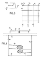
- - la figure 3 correspond à une variante de la figure 2,
- - la figure 4 est un schéma d'une tête magnétique selon l'invention, et
- - les figures 5 à 8 sont des schémas et diagrammes illustrant le fonctionnement de la tête magnétique de la figure 4.
- On a représenté sur la figure 1 un dispositif matriciel à têtes magnétiques pour l'enregistrement d'informations sur un support magnétique tel qu'un bande (non montrée) à pluralité de pistes.
- Ce dispositif matriciel comporte une plaque en matériau magnétique, par exemple en ferrite, de laquelle sont en saillie des blocs 10₁, 10₂, 10₃, 10₄, 10₅, etc... de section rectangulaire et séparés par des rainures 11₁, 11₂... 12₁, 12₂...
- Les rainures 12₁, 12₂, etc sont parallèles entre elles et perpendiculaires aux rainures 11₁, 11₂...
- Dans les rainures 11 de ligne sont disposés des fils conducteurs rectilignes 13₁, 13₂... Dans les rainures 12 de colonne sont également disposés des fils conducteurs rectilignes 14₁, 14₂....
- La surface libre d'extrémité de chaque bloc magnétique 10₁ rectangulaire est recouverte par une couche 15 d'un matériau magnétique qui se prolonge à un coin, dans la direction d'une diagonale du rectangle, selon une bande 16 séparée par un entrefer 17 d'une bande correspondante 18 prolongeant une autre couche magnétique 19 sur un bloc voisin 10₅ dont la diagonale de la surface rectangulaire prolonge la diagonale correspondante du bloc 10₁.
- Les conducteurs 13₁, 14₁ qui sont au droit de l'entrefer 17 produisent un champ magnétique pour l'inscription d'une information sur un support magnétique qui, bien entendu, est disposé au voisinage de l'entrefer 17.
- Dans un premier exemple (figure 2) certains des conducteurs sont parcourus par un courant d'intensité I et d'atures conducteurs sont parcourus par un courant d'intensité -I/3. Une tête magnétique inscrit une information sur le support magnétique quand les deux conducteurs associés à cette tête sont parcourus par un courant d'intensité I. Par contre si l'un des deux conducteurs, ou les deux conducteurs, est (sont) parcouru(s) par un courant d'intensité - I/3 il n'y a pas d'information inscrite par la tête magnétique correspondante sur le support magnétique.
- On voit ainsi que lorsque le courant d'excitation a la valeur 2I, une information est inscrite; par contre quand ce courant d'excitation a la valeur 2I/3 ou -2I/3 aucune information n'est inscrite sur le support.
- On comprend donc que pour un courant d'excitation d'intensité ± 2I/3, il est préférable que la tête magnétique ne provoque aucune aimantation du support alors que pour un courant d'excitation d'intensité 2I il est préférable que l'aimantation du support magnétique soit maximum. Ce but est atteint, conformément à l'invention, grâce à la tête qui sera décrite plus loin en relation avec la figure 4.
- Dans un autre exemple (figure 3) pour l'inscription d'informations binaires (1 ou 0) chaque ligne est parcourue par deux impulsions successives : une impulsion positive, c'est-à-dire un courant d'intensité +2I/3, suivie par une impulsion négative, c'est-à-dire un courant d'intensité -2I/3. Si on désire inscrire un chiffre "1", la colonne correspondante est parcourue par un courant +I/3 tandis que si on désire inscrire le chiffre "0" on fait passer un courant d'intensité -I/3 dans la colonne correspondante. Ainsi quand la colonne est parcourue par un courant d'intensité +I/3 au cours de l'impulsion positive 2I/3 de la ligne, le courant d'excitation à l'intensité I suffisante pour inscrire une information, tandis qu'au cours de l'impulsion négative -2I/3 sur la ligne, le courant d'excitation est -I/3, insuffisant pour inscrire une information.
- De même quand une colonne est parcourue par un courant d'intensité -I/3 au cours de l'impulsion positive 2I/3 sur la ligne, le courant d'excitation de la tête correspondante est I/3, insuffisant pour inscrire une information tandis qu'au cours de l'impulsion négative le courant d'excitation est -I, ce qui permet l'inscription d'un "0".
- Bien entendu dans le mode de réalisation de la figure 3, les lignes sont adressées une par une pour l'inscription d'informations.
- Dans cette réalisation, comme dans la précédente, il est préférable qu'une excitation correspondant à une intensité de courant de +I/3 ou -I/3 ne provoque aucune aimantatlon du support alors qu'une excitation correspondant à un courant d'intensité I devra produire une aimantation maximum du support magnétique.
- Pour obtenir ce résultat, le matériau 20 d'entrefer de la tête magnétique 21 selon l'invention (figure 4) est un matériau magnétique saturable à valeur de saturation inférieure à celle du matériau, ou des matériaux, constituant les pôles magnétiques 22 et 23.
- Pour améliorer encore l'effet de l'entrefer 20 en matériau saturable, l'ensemble formé par les pôles 22 et 23 et l'entrefer 20 est séparé des blocs en ferrite 10₁ et 10₅ par une couche 25 en matériau non magnétique.
- Le fonctionnement est le suivant :
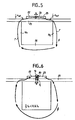
- Lorsque la valeur absolue de la somme des courants d'excitation dans les conducteurs 13₁ et 14₁ est inférieure au tiers d'une valeur I₀ prédéterminée, le flux du champ magnétique, circule comme représenté par les flèches F sur la figure 5, dans le circuit magnétique comprenant : le substrat 26 en ferrite avec ses blocs en saillie 10₁ et 10₅, la couche non magnétique 25, les pôles 22 et 23 et l'entrefer 20. Dans ce cas (intensité inférieure à I₀/3) le matériau magnétique de l'entrefer 20 n'est pas saturé et, ainsi, le champ magnétique reste confiné dans cet entrefer.
- Par contre quand la valeur absolue de la somme des intensités des courants circulant dans les conducteurs 13₁ et 14₁ dépasse la valeur I₀/3, le matériau constituant l'entrefer 20 est saturé et ainsi, comme représenté sur la figure 6, le champ magnétique ne reste pas confiné dans l'entrefer . Une partie F₁ passe dans la couche non magnétique 25 et une autre partie F₂ s'éloigne de cet entrefer à l'opposé de la couche 25. C'est cette partie F₂ du champ magnétique qui est utilisée pour l'écriture sur un support magnétique (non représenté).
- On obtient bien le résultat recherché : le support magnétique n'est pas aimanté quand la valeur absolue de la somme des courants dans les conducteurs 13₁et 14₁ ne dépasse pas I₀/3. Par contre l'aimantation du support magnétique intervient dès que ladite valeur absolue de la somme des intensités dépasse I₀/3, valeur à partir de laquelle le matériau de l'entrefer 20 est saturé.
- Dans l'exemple les pôles 22 et 23 sont en sendust, c'est-à-dire en un alliage de fer, d'aluminium et de silicium comprenant par exemple en pourcentage atomique 74 % de fer, 9 % d'aluminium et 17 % de silicium.
- Par contre le matériau de l'entrefer 20 est un sendust dégradé, c'est-à-dire un matériau à aimantation à saturation plus faible par exemple dont la proportion d'aluminium est supérieure à celle dudit sendust. Ce sendust dégradé contient en pourcentage atomique par exemple 64 % de fer, 15 % d'aluminium et 21 % de silicium.
- En variante le matériau de l'entrefer 20 est une ferrite ou un autre matériau magnétique.
- Il est également possible de réaliser l'entrefer dans le même matériau que les pôles 22 et 23, mais à condition de lui conférer une section plus faible que celle des pôles. Dans ce cas, c'est par exemple la profondeur (dimension perpendiculaire au support) de l'entrefer qui est plus petite que la profondeur des pôles.
- La couche non magnétique 25 introduit dans le circuit magnétique une réluctance de forte valeur qui contribue à l'obtention du résultat recherché, à savoir la non saturation pour des intensités de courant qui, en valeur absolue, sont inférieures à I₀/3 et la saturation du matériau 20 pour des excitations de courant correspondant à des valeurs absolues supérieures à I₀/3.
- Bien entendu la valeur de cette réluctance dépend des dimensions et de la géométrie du circuit magnétique ainsi que de la nature du matériau de l'entrefer.
- Le fait que la saturation du matériau 20 intervienne pour un courant I₀/3 se traduit par la relation suivante :

- φsat représente le flux circulant dans le circuit magnétique. Ce flux est proportionnel à l'épaisseur e de l'entrefer 20 et à l'aimantation du matériau magnétique dans cet entrefer.
- Pour obtenir une valeur maximum de flux d'écriture F₂ pour I = I₀ on se base sur les considérations suivantes :
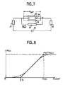
- L'équivalent électrique du circuit magnétique de la figure 6 est représenté sur la figure 7 : le générateur 30 est un générateur de force magnétomotrice correspondant à un courant d'excitation I compris entre et I₀/3 et I₀. Les éléments 31 et 32 sont les deux éléments correspondant aux réluctances½ Rsat. L'élément 33 en série entre les éléments 31 et 32 correspond à la réluctance du matériau d'entrefer non saturé. Sur cette réluctance 33 sont en parallèle trois autres réluctances 34, 35 et 36. La réluctance 34 correspond à la partie du flux dépassant la valeur de saturation qui passe dans l'entrefer 20. La réluctance 35 correspond au flux F₂ tandis que la réluctance 36 est la réluctance s'opposant au passage du flux F₁.
- Le circuit représenté sur la figure 7 traduit le fait que, pour une intensité I comprise, en valeur absolue, entre I₀/3 et I₀, la partie φsat du flux qui provoque la saturation voit le matériau magnétique saturé, donc à faible perméabilité, tandis que le reste du flux φ - φsat (engendré par le courant I - I₀/3) circule dans le circuit comme avec un entrefer classique rempli d'un matériau non magnétique. Dans ce cas la réluctance équivalente aux réluctances 33, 34, 35 et 36 en parallèle n'est pas petite devant la valeur des réluctances 31 et 32.
- Le flux d'écriture F₂ est maximum pour I =I₀ si, pour ce courant, les pôles 22 et 23 se saturent. Au-delà de la saturation le champ magnétique d'écriture n'augmente plus. Cette propriété est représentée sur le diagramme de la figure 8 où l'on a porté, en abscisses, l'intensité I du courant d'excitation qui représente la somme des intensités dans les conducteurs 13₁ et 14₁ et, en ordonnées, le champ magnétique Hécr d'écriture. On voit sur cette figure 8 que si |I| < I₀/3, le champ magnétique d'écriture est nul tandis que pour |I| > Imax (Imax = I₀) le champ magnétique d'écriture reste pratiquement constant.
- On pourra comprendre de façon plus précise le comportement du circuit magnétique à partir d'un exemple pour lequel :
Rsat = Rgap (2) - Dans cette formule Rgap représente la réluctance équivalent aux réluctances 34, 35 et 36 en parallèle. On suppose que la valeur Rsat (et donc Rgap) est connue; il faut d'ailleurs noter que la valeur Rgap est imposée par la largeur de piste à inscrire, la largeur e de l'entrefer et l'épaisseur de la couche de matériau magnétique formant les pôles 22 et 23.
- On cherche alors a calculer φsat et I₀ = Imax (figure 8)
- Le flux total correspond au flux maximal permis pour une excitation d'intensité I₀.
- La considération du circuit de la figure 7 permet d'écrire la formule suivante :

- Des formules (1) et (5) ci-dessus on déduit :
φsat = ½ φmax (6)
Ainsi la moitié de la valeur de saturation du matériau des pôles 22 et 23 est disponible pour la création du champ magnétique d'écriture si, pour l'entrefer 20 et pour les pôles 22 et 23, on utilise des matériaux et configurations qui satisfont à la relation (2) ci-dessus. - Dans l'exemple où les pôles 22 et 23 sont en sendust, la densité maximale de flux correspondant à φmax est d'environ 10 000 G. Si Rsat = Rgap on peut donc profiter de 5 000 G pour l'écriture. L'intensité du courant I₀ est alors de l'ordre de 5 A.
- Dans le cas général si on augmente la réluctance Rsat introduite par la couche non magnétique 25 on augmente la proportion du flux magnétique qui est utilisable pour inscrire une information par rapport au flux φsat servant à saturer l'entrefer. En effet le flux maximum utile pour l'inscription est φmax - φsat et ladite proportion est donc :

- Ce rapport est d'autant plus grand que Rsat est grand par rapport à Rgap. Toutefois si Rsat augmente il faut augmenter I₀.
- Bien que l'exemple décrit se rapporte à un dispositif à pluralité de têtes magnétiques, l'invention s'applique aussi à un dispositif à tête magnétique unique permettant d'aimanter un support magnétique à partir d'une valeur déterminée du courant d'excitation.
Claims (15)
Applications Claiming Priority (2)
| Application Number | Priority Date | Filing Date | Title |
|---|---|---|---|
| FR8814806 | 1988-11-15 | ||
| FR8814806A FR2639137B1 (fr) | 1988-11-15 | 1988-11-15 | Tete magnetique a entrefer saturable et dispositif matriciel comportant un ensemble de telles tetes |
Publications (2)
| Publication Number | Publication Date |
|---|---|
| EP0369839A1 true EP0369839A1 (fr) | 1990-05-23 |
| EP0369839B1 EP0369839B1 (fr) | 1994-05-25 |
Family
ID=9371848
Family Applications (1)
| Application Number | Title | Priority Date | Filing Date |
|---|---|---|---|
| EP89402896A Expired - Lifetime EP0369839B1 (fr) | 1988-11-15 | 1989-10-20 | Tête magnétique à entrefer saturable et dispositif matriciel comportant un ensemble de telles têtes |
Country Status (6)
| Country | Link |
|---|---|
| US (1) | US5063467A (fr) |
| EP (1) | EP0369839B1 (fr) |
| JP (1) | JPH02173906A (fr) |
| KR (1) | KR900008446A (fr) |
| DE (1) | DE68915511T2 (fr) |
| FR (1) | FR2639137B1 (fr) |
Families Citing this family (14)
| Publication number | Priority date | Publication date | Assignee | Title |
|---|---|---|---|---|
| US5146379A (en) * | 1990-05-30 | 1992-09-08 | Alps Electric Co., Ltd. | Thin film magnetic head |
| FR2668289B1 (fr) * | 1990-10-19 | 1992-12-11 | Thomson Consumer Electronics | Procede d'adressage de tetes elementaires d'une tete multipiste d'enregistrement sur support magnetique et tete magnetique le mettant en óoeuvre. |
| FR2685518B1 (fr) * | 1991-12-23 | 1994-02-04 | Thomson Csf | Circuit d'horloge pour systeme de lecture d'informations sequentielles. |
| FR2689293B1 (fr) * | 1992-03-27 | 1994-05-13 | Thomson Csf | Dispositif de lecture d'un ensemble d'elements resistifs. |
| FR2712419B1 (fr) * | 1993-11-09 | 1995-12-22 | Thomson Csf | Tête magnétique d'enregistrement/lecture. |
| FR2723242B1 (fr) | 1994-07-26 | 1996-08-30 | Thomson Csf | Tete magnetique a element saturable et dispositif matriciel comportant un ensemble de tetes magnetiques |
| US5748737A (en) * | 1994-11-14 | 1998-05-05 | Daggar; Robert N. | Multimedia electronic wallet with generic card |
| FR2735269B1 (fr) * | 1995-06-06 | 1997-07-25 | Thomson Csf | Tete d'enregistrement/lecture matricielle a structure zigzag |
| DE19852037A1 (de) * | 1998-11-11 | 2000-05-18 | Thomson Brandt Gmbh | Magnetbandgerät mit Treiberschaltung für Matrixkopf |
| US6865056B1 (en) | 1999-10-05 | 2005-03-08 | Seagate Technology Llc | Longitudinal magnetic recording heads with variable-length gaps |
| US6865057B2 (en) * | 1999-10-05 | 2005-03-08 | Seagate Technology Llc | Gapless longitudinal magnetic recording head with flux cavity |
| US6650496B2 (en) | 2001-05-15 | 2003-11-18 | Phs Mems | Fully integrated matrix magnetic recording head with independent control |
| KR20040069062A (ko) * | 2003-01-28 | 2004-08-04 | 삼성전자주식회사 | 자기 기록헤드 |
| US8134801B2 (en) * | 2007-03-19 | 2012-03-13 | Dimambro Bryan | Electromagnetic data storage devices |
Citations (5)
| Publication number | Priority date | Publication date | Assignee | Title |
|---|---|---|---|---|
| US3485962A (en) * | 1966-11-09 | 1969-12-23 | Gen Electric | Magnetic transducer head with remanent flux shunt gap spacer |
| US4380768A (en) * | 1980-08-04 | 1983-04-19 | Dataproducts Corporation | Magnetic printer and printhead |
| US4646184A (en) * | 1983-09-21 | 1987-02-24 | Ye Data Inc. | Magnetic head for recording and reproduction |
| FR2605783A1 (fr) * | 1986-10-28 | 1988-04-29 | Thomson Csf | T ete magnetique d'enregistrement/lecture en couches minces et son procede de realisation |
| EP0097836B1 (fr) * | 1982-06-30 | 1989-10-04 | International Business Machines Corporation | Appareil pour l'enregistrement magnétique |
Family Cites Families (8)
| Publication number | Priority date | Publication date | Assignee | Title |
|---|---|---|---|---|
| US4342039A (en) * | 1979-08-27 | 1982-07-27 | General Electric Company | High resolution magnetic printing head |
| DE3171213D1 (en) * | 1980-08-25 | 1985-08-08 | Matsushita Electric Industrial Co Ltd | Magnetic transducer with built-in step-up transformer |
| JPS57212614A (en) * | 1981-06-23 | 1982-12-27 | Nec Corp | Electromagnetic head |
| JPS5832219A (ja) * | 1981-08-19 | 1983-02-25 | Matsushita Electric Ind Co Ltd | ステツプアツプ型磁気ヘツド |
| JPS6066310A (ja) * | 1983-09-21 | 1985-04-16 | Yaskawa Electric Mfg Co Ltd | 磁気ヘツド |
| JPS60163214A (ja) * | 1984-02-03 | 1985-08-26 | Canon Electronics Inc | 磁気ヘツド及びその製造方法 |
| US4780779A (en) * | 1987-11-19 | 1988-10-25 | Ampex Corporation | Laminated sendust metal-in-gap video head |
| FR2630853B1 (fr) * | 1988-04-27 | 1995-06-02 | Thomson Csf | Dispositif matriciel a tetes magnetiques notamment en couches minces |
-
1988
- 1988-11-15 FR FR8814806A patent/FR2639137B1/fr not_active Expired - Lifetime
-
1989
- 1989-10-20 DE DE68915511T patent/DE68915511T2/de not_active Expired - Fee Related
- 1989-10-20 EP EP89402896A patent/EP0369839B1/fr not_active Expired - Lifetime
- 1989-10-27 KR KR1019890015498A patent/KR900008446A/ko not_active Ceased
- 1989-10-27 JP JP1281582A patent/JPH02173906A/ja active Pending
- 1989-10-27 US US07/427,369 patent/US5063467A/en not_active Expired - Fee Related
Patent Citations (5)
| Publication number | Priority date | Publication date | Assignee | Title |
|---|---|---|---|---|
| US3485962A (en) * | 1966-11-09 | 1969-12-23 | Gen Electric | Magnetic transducer head with remanent flux shunt gap spacer |
| US4380768A (en) * | 1980-08-04 | 1983-04-19 | Dataproducts Corporation | Magnetic printer and printhead |
| EP0097836B1 (fr) * | 1982-06-30 | 1989-10-04 | International Business Machines Corporation | Appareil pour l'enregistrement magnétique |
| US4646184A (en) * | 1983-09-21 | 1987-02-24 | Ye Data Inc. | Magnetic head for recording and reproduction |
| FR2605783A1 (fr) * | 1986-10-28 | 1988-04-29 | Thomson Csf | T ete magnetique d'enregistrement/lecture en couches minces et son procede de realisation |
Non-Patent Citations (1)
| Title |
|---|
| PATENT ABSTRACTS OF JAPAN * |
Also Published As
| Publication number | Publication date |
|---|---|
| EP0369839B1 (fr) | 1994-05-25 |
| DE68915511D1 (de) | 1994-06-30 |
| FR2639137B1 (fr) | 1990-12-21 |
| US5063467A (en) | 1991-11-05 |
| JPH02173906A (ja) | 1990-07-05 |
| DE68915511T2 (de) | 1994-09-08 |
| FR2639137A1 (fr) | 1990-05-18 |
| KR900008446A (ko) | 1990-06-04 |
Similar Documents
| Publication | Publication Date | Title |
|---|---|---|
| EP0340085B1 (fr) | Dispositif matriciel à têtes magnétiques, notamment en couches minces | |
| EP0369839B1 (fr) | Tête magnétique à entrefer saturable et dispositif matriciel comportant un ensemble de telles têtes | |
| EP0284495B1 (fr) | Tête magnétique de lecture pour piste de très faible largeur et procédé de fabrication | |
| EP0107589B1 (fr) | Dispositif d'écriture d'informations sur un support magnétique | |
| KR920018653A (ko) | 자성박막 메모리 및 그 기록·재생방법 | |
| EP0467737A1 (fr) | Dispositif magnétique de lecture à réseau matriciel de têtes de lecture | |
| EP0467736B1 (fr) | Tête magnétique de lecture à effet magnéto-résistif | |
| EP0046697B1 (fr) | Transducteur magnétique intégré | |
| FR2817622A1 (fr) | Micromagnetometre a porte de flux | |
| US6101067A (en) | Thin film magnetic head with a particularly shaped magnetic pole piece and spaced relative to an MR element | |
| EP0409675B1 (fr) | Tête d'enregistrement magnétique multipiste à grand contraste de champ | |
| EP0481875B1 (fr) | Procédé d'adressage de têtes élémentaires d'une tête multipiste d'enregistrement sur support magnétique, et tête magnétique le mettant en oeuvre | |
| EP0040994B1 (fr) | Transducteur magnétique à entrefer de grande dimension variable pour la lecture ou l'écriture des informations d'un support magnétique | |
| EP0434547B1 (fr) | Tête de lecture multipiste | |
| FR2671220A1 (fr) | Procede de fabrication de capteurs magneto-resistifs, et dispositif magnetique realise suivant un tel procede. | |
| EP0041409A1 (fr) | Transducteur magnétique pour la lecture ou l'écriture des informations d'un support magnétique | |
| FR2468183A1 (fr) | Transducteur magnetique integre | |
| EP0694909A1 (fr) | Tête magnétique à élément saturable et dispositif matriciel comportant un ensemble de têtes magnétiques | |
| JPS592087B2 (ja) | ジキヘツド | |
| WO1990016062A2 (fr) | Tete magnetique integree d'enregistrement | |
| JPS62137713A (ja) | 磁気抵抗効果型磁気ヘツド | |
| FR2617629A1 (fr) | Memoire a ligne de bloch et procede pour transferer une ligne de bloch | |
| JP2002042457A (ja) | 磁性メモリ | |
| US5689225A (en) | Method for driving magneto-resistive element | |
| JPS61104401A (ja) | 薄膜磁気ヘツド記録方式 |
Legal Events
| Date | Code | Title | Description |
|---|---|---|---|
| PUAI | Public reference made under article 153(3) epc to a published international application that has entered the european phase |
Free format text: ORIGINAL CODE: 0009012 |
|
| AK | Designated contracting states |
Kind code of ref document: A1 Designated state(s): DE GB IT NL |
|
| 17P | Request for examination filed |
Effective date: 19900618 |
|
| 17Q | First examination report despatched |
Effective date: 19930209 |
|
| RAP1 | Party data changed (applicant data changed or rights of an application transferred) |
Owner name: THOMSON-CSF |
|
| GRAA | (expected) grant |
Free format text: ORIGINAL CODE: 0009210 |
|
| AK | Designated contracting states |
Kind code of ref document: B1 Designated state(s): DE GB IT NL |
|
| ITF | It: translation for a ep patent filed | ||
| REF | Corresponds to: |
Ref document number: 68915511 Country of ref document: DE Date of ref document: 19940630 |
|
| GBT | Gb: translation of ep patent filed (gb section 77(6)(a)/1977) |
Effective date: 19940623 |
|
| PLBE | No opposition filed within time limit |
Free format text: ORIGINAL CODE: 0009261 |
|
| STAA | Information on the status of an ep patent application or granted ep patent |
Free format text: STATUS: NO OPPOSITION FILED WITHIN TIME LIMIT |
|
| 26N | No opposition filed | ||
| PGFP | Annual fee paid to national office [announced via postgrant information from national office to epo] |
Ref country code: GB Payment date: 19960918 Year of fee payment: 8 |
|
| PGFP | Annual fee paid to national office [announced via postgrant information from national office to epo] |
Ref country code: DE Payment date: 19960919 Year of fee payment: 8 |
|
| PGFP | Annual fee paid to national office [announced via postgrant information from national office to epo] |
Ref country code: NL Payment date: 19960926 Year of fee payment: 8 |
|
| PG25 | Lapsed in a contracting state [announced via postgrant information from national office to epo] |
Ref country code: GB Free format text: LAPSE BECAUSE OF NON-PAYMENT OF DUE FEES Effective date: 19971020 |
|
| PG25 | Lapsed in a contracting state [announced via postgrant information from national office to epo] |
Ref country code: NL Free format text: LAPSE BECAUSE OF NON-PAYMENT OF DUE FEES Effective date: 19980501 |
|
| GBPC | Gb: european patent ceased through non-payment of renewal fee |
Effective date: 19971020 |
|
| NLV4 | Nl: lapsed or anulled due to non-payment of the annual fee |
Effective date: 19980501 |
|
| PG25 | Lapsed in a contracting state [announced via postgrant information from national office to epo] |
Ref country code: DE Free format text: LAPSE BECAUSE OF NON-PAYMENT OF DUE FEES Effective date: 19980701 |
|
| PG25 | Lapsed in a contracting state [announced via postgrant information from national office to epo] |
Ref country code: IT Free format text: LAPSE BECAUSE OF NON-PAYMENT OF DUE FEES Effective date: 20051020 |