EP0369850B1 - Gangschaltgetriebe - Google Patents
Gangschaltgetriebe Download PDFInfo
- Publication number
- EP0369850B1 EP0369850B1 EP89402962A EP89402962A EP0369850B1 EP 0369850 B1 EP0369850 B1 EP 0369850B1 EP 89402962 A EP89402962 A EP 89402962A EP 89402962 A EP89402962 A EP 89402962A EP 0369850 B1 EP0369850 B1 EP 0369850B1
- Authority
- EP
- European Patent Office
- Prior art keywords
- shaft
- pinions
- pinion
- driving
- driven
- Prior art date
- Legal status (The legal status is an assumption and is not a legal conclusion. Google has not performed a legal analysis and makes no representation as to the accuracy of the status listed.)
- Expired - Lifetime
Links
- 230000005540 biological transmission Effects 0.000 title claims description 26
- 230000004323 axial length Effects 0.000 description 2
- 230000018109 developmental process Effects 0.000 description 1
Images


Classifications
-
- F—MECHANICAL ENGINEERING; LIGHTING; HEATING; WEAPONS; BLASTING
- F16—ENGINEERING ELEMENTS AND UNITS; GENERAL MEASURES FOR PRODUCING AND MAINTAINING EFFECTIVE FUNCTIONING OF MACHINES OR INSTALLATIONS; THERMAL INSULATION IN GENERAL
- F16H—GEARING
- F16H3/00—Toothed gearings for conveying rotary motion with variable gear ratio or for reversing rotary motion
- F16H3/02—Toothed gearings for conveying rotary motion with variable gear ratio or for reversing rotary motion without gears having orbital motion
- F16H3/08—Toothed gearings for conveying rotary motion with variable gear ratio or for reversing rotary motion without gears having orbital motion exclusively or essentially with continuously meshing gears, that can be disengaged from their shafts
- F16H3/087—Toothed gearings for conveying rotary motion with variable gear ratio or for reversing rotary motion without gears having orbital motion exclusively or essentially with continuously meshing gears, that can be disengaged from their shafts characterised by the disposition of the gears
- F16H3/091—Toothed gearings for conveying rotary motion with variable gear ratio or for reversing rotary motion without gears having orbital motion exclusively or essentially with continuously meshing gears, that can be disengaged from their shafts characterised by the disposition of the gears including a single countershaft
-
- F—MECHANICAL ENGINEERING; LIGHTING; HEATING; WEAPONS; BLASTING
- F16—ENGINEERING ELEMENTS AND UNITS; GENERAL MEASURES FOR PRODUCING AND MAINTAINING EFFECTIVE FUNCTIONING OF MACHINES OR INSTALLATIONS; THERMAL INSULATION IN GENERAL
- F16H—GEARING
- F16H2200/00—Transmissions for multiple ratios
- F16H2200/003—Transmissions for multiple ratios characterised by the number of forward speeds
- F16H2200/0052—Transmissions for multiple ratios characterised by the number of forward speeds the gear ratios comprising six forward speeds
Definitions
- the present invention relates to a gearbox of the type comprising an input drive shaft and a parallel output receiver shaft, each carrying respectively drive gears and take-up gears which mesh in pairs to form pairs of drive and take-off gears, each produces a transmission ratio between the input shaft and the output shaft, one of the two pinions of each of the pairs being linked in rotation with the shaft which carries it and the other of the two pinions being mounted free to rotate on the shaft which carries it and to which it can be linked in rotation to produce a transmission ratio.
- a first solution known from documents EP-A-0224407 and EP-A-0206563 consists in proposing a gearbox which comprises an intermediate shaft, parallel to the input and output shafts, which carries at least one intermediate pinion which meshes with one of said drive pinions, or receivers, which is linked in rotation to the drive shaft, or receiver, which carries it, the other receiver shaft, or drive, being linked in rotation to the intermediate shaft so as to rotate in the same direction, said intermediate pinion being mounted to rotate freely on the intermediate shaft which carries it and to which it can be linked in rotation to produce at least one additional transmission ratio.
- the present invention aims to provide a simple, economical and compact design of such a type of gearbox.
- the transmission means which ensure the rotational connection of the intermediate shaft to said other receiving shaft, or motor, comprise a transmission chain
- the gearbox shown in Figures 1 and 2 comprises an input drive shaft 10, a shaft output receiver 20, an intermediate shaft 30 and a reverse shaft 40 which are all four parallel to each other.
- the input drive shaft carries four forward drive pinions 11, 12, 13 and 14 as well as a reverse gear 10AR which are all five linked in rotation to the drive shaft 10.
- the output receiving shaft 20 carries four forward gear receiving pinions 21, 22, 23 and 24 which are all mounted to rotate freely on the receiving shaft 20.
- a portable player B1-2 is slidably mounted on the receiving shaft 20 between the receiving pinions 21 and 22.
- the portable player B1-2 is capable, under the action of a control fork F1-2, of linking in rotation the either of the receiving gears 21 or 22 to the receiving shaft 20.
- a portable player B3-4 is slidably mounted on the receiving shaft 20 between the two receiving pinions 23 and 24.
- the portable player B3-4 is capable, under the action of a control fork F3-4, of rotationally link one or other of the receiving pinions 23 or 24 to the receiving shaft 20.
- the first four forward ratios correspond to the pairs of motor-receiver pinions 11-21, 12-22, 13-23 and 14-24 respectively.
- the intermediate shaft 30 carries a first intermediate gear 35 which meshes with the receiving gear 13 of the third forward gear, and which is identical to the receiving gear 23 of the third forward gear.
- the intermediate shaft 30 carries a second intermediate pinion 36 which meshes with the receiving pinion 14 of the fourth forward gear, and which is identical to the receiving pinion 24 of the fourth forward gear.
- a portable player B5-6 is slidably mounted on the intermediate shaft 30 between the intermediate pinions 35 and 36.
- the portable player B5-6 is capable, under the action of a control fork F5-6, of linking in rotation the either of the two intermediate gears 35 and 36 has the intermediate shaft 30 which carries them and on which they are normally mounted free to rotate.
- the intermediate shaft 30 is linked in rotation to the output shaft 20 by a transmission chain 50 which cooperates with a transmission pinion 30T carried by the intermediate shaft 30 as well as with a transmission pinion 20T carried by the output shaft 20.
- the number of teeth of the transmission pinion 30T is greater than that of the pinion 20T so that the output shaft is driven by the intermediate shaft at a speed of rotation greater than that of the latter.
- the fifth forward gear ratio of the gearbox shown in FIGS. 1 and 2 corresponds to the torque formed by the drive gear 13 of the third forward gear which meshes with the first intermediate gear 35 carried by the receiving shaft 30.
- the sixth forward gear corresponds to the torque formed by the drive pinion 14 of the fourth forward gear which meshes with the second intermediate gear 36 carried by the intermediate shaft.
- the reverse gear shaft 40 carries a reverse gear pinion 40AR which meshes with the motor pinion 10AR carried by the motor shaft 10.
- the output shaft 20 finally carries a pinion 20P output which is linked to it in rotation and which meshes with a crown wheel 52 of the differential 54 of the transmission of the motor vehicle (not shown) equipped with the gearbox.
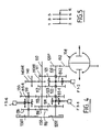
- FIG. 4 The second embodiment of a gearbox shown in FIG. 4 will now be described in which the elements identical or similar to those of FIG. 1 are designated by the same reference numbers increased by 100.
- the intermediate shaft 130 carries a first intermediate pinion 135 mounted to rotate freely on the intermediate shaft 130 which meshes with the motor pinion 113 of the third forward gear carried by the motor shaft 110 and which is identical to the receiving pinion 123 of the third forward gear carried by the output shaft 120.
- the second intermediate pinion 136 mounted to rotate freely on the intermediate shaft 130 meshes with an additional motor pinion 116 linked in rotation with the motor shaft 110 which carries it.
- the output shaft 120 is also rotated by the intermediate shaft 130 at a higher speed of rotation than the latter.
- the fifth forward gear is produced by the torque formed by the first intermediate gear 135 which meshes with the motor gear 113 of the third forward gear.
- the sixth forward gear is produced by the torque formed by the second intermediate pinion 136 which meshes with the additional motor pinion 116 carried by the motor shaft 110.
- This second embodiment makes it possible to obtain any desirable freedom of staging of the gearbox while retaining an axial size of the box identical to that of a conventional five-speed gearbox.
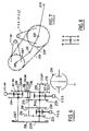
- the input drive shaft 210 carries four drive pinions 212, 213, 214 and 215 which are linked to it in rotation.
- the output receiving shaft 220 carries four receiving pinions 222, 223, 224 and 225 which are mounted to rotate freely on the output shaft 220.
- a first B2-3 player is slidably mounted on the output shaft 220 between the two receiving pinions 222 and 223.
- the B2-3 player is capable of rotationally linking one of the two receiving pinions 222 or 223 to the shaft output 220 under the action of an F2-3 control fork.
- a second B4-5 player is slidably mounted on the output shaft 220 between the two receiving pinions 224 and 225.
- the B4-5 player is capable of rotationally linking one or the other of the two pinions receivers 224 or 225 at the output shaft 220 under the action of a control fork F4-5.
- the second, third, fourth and fifth forward gear ratios of the gearbox are produced by the pairs of motor-receiver gears 212-222, 213-223, 214-224 and 215-225 respectively.
- the intermediate shaft 230 carries a first intermediate pinion 231 which is mounted to rotate freely on the intermediate shaft 230 and which meshes with the motor pinion 212 linked in rotation to the input shaft 210.
- the driving pinion 212 has a large axial thickness so as to be able to mesh simultaneously with the receiving pinion of the second forward gear 222 as well as with the first intermediate pinion 231.
- the intermediate shaft 230 carries a second intermediate pinion 230AR also mounted to rotate freely on the intermediate shaft 230.
- a walkman B1-AR is slidably mounted on the intermediate shaft 230 between the intermediate pinions 231 and 230AR.
- the player B1-AR is capable of rotationally linking one or the other of the two intermediate pinions 231, or 230 AR to the intermediate shaft 230 under the action of a control fork F1-AR.
- the second intermediate gear 230AR meshes with a reverse gear 240AR carried by the reverse shaft 240.
- the 240AR reverse pinion also meshes with the large axial thickness motor pinion 212 carried by the motor shaft 210.
- the first forward gear ratio is produced by the torque formed by the first intermediate pinion 231 and the motor pinion 212 of the second forward gear.
- the transmission pinion 230T carried by the intermediate shaft 230 has a number of teeth less than that of the transmission number 220T carried by the output shaft 220 so that the intermediate shaft 230 drives the output shaft 220 at a lower rotational speed than that of the intermediate shaft 230.
- the first intermediate pinion 231 therefore makes it possible to produce an additional transmission ratio of rank lower than that of the motor pinion 212 with which it meshes.
- the reverse gear transmission ratio is achieved by the torque formed by the second intermediate gear 230AR and the reverse gear 240.
- the control grid of the gearbox shown in FIG. 8 is an offset grid which is in particular usable for commercial vehicles for the use of which starting in second forward gear is commonly used when the vehicle is idle.
- the drive shaft 310 carries two first forward drive pinions 311 and 312 which are linked in rotation to the shaft 310, then a third and a fourth forward drive pinions 313 and 314 which are mounted free in rotation on the shaft engine 310.
- a portable player B3-4 is slidably mounted on the motor shaft 310 between the motor pinions 313 and 314.
- the portable player B3-4 is capable of rotationally linking one or the other of the motor pinions 313 and 314 to the shaft 310 engine under the action of an F3-4 control fork.
- the output shaft 320 carries a first and a second receiving pinions 321 and 322 which are mounted to rotate freely on the receiving shaft 320, as well as a third and a fourth receiving pinions 323 and 324 which are linked in rotation to the receiver shaft 320.
- a portable player B1-2 is slidably mounted on the receiving shaft 320 between the receiving pinions 321 and 322.
- the portable player B1-2 is capable of rotationally linking one or the other of the receiving pinions 321 or 322 to the shaft output 320 under the action of a control fork F1-2.
- the first four forward gears are produced by the engine-receiver pinion pairs 311-321, 312-322, 313-323 and 314-324 respectively.
- the intermediate shaft 330 carries a first intermediate pinion 335 which meshes with the pinion receiving the third forward gear 323 and is identical to the drive pinion of the third forward gear 313.
- the intermediate shaft 330 carries a second intermediate pinion 336 which is also mounted free in rotation on the intermediate shaft 330.
- the second intermediate pinion 336 meshes with the pinion receiving the fourth forward gear 324 and is identical to the motor pinion 314 of fourth forward gear.
- the intermediate shaft 330 is rotated by the input drive shaft 310 by means of a cascade of pinions.
- This cascade of pinions comprises a first transmission pinion 310T linked in rotation to the motor shaft 310, an intermediate pinion 360 mounted free in rotation on a parallel shaft 60 and a transmission pinion 330T is linked in rotation to the intermediate shaft 330 who wears it.
- the numbers of teeth of the cascade pinions are chosen so that the intermediate shaft 330 is linked in rotation to the input drive shaft 310 to be driven in rotation at a speed greater than that of the latter.
- the fifth and sixth additional forward gears are produced by the cascade of pinions and by the pairs formed respectively by the first intermediate pinion 335 and the third gear receiving gear 323, and by the second intermediate gear 336 and the fourth gear receiving forward gear 324.
- the intermediate shaft 330 carries a sliding walkman B5-6 disposed between the intermediate pinions 335 and 336.
- the walkman B5-6 is capable of rotationally linking the one or the other of the intermediate pinions 335 or 336 under the action of a control fork F5-6.
Landscapes
- Engineering & Computer Science (AREA)
- General Engineering & Computer Science (AREA)
- Mechanical Engineering (AREA)
- Structure Of Transmissions (AREA)
Claims (13)
- Schaltgetriebe des Typs mit einer eingangsseitigen antreibenden Welle (10) und einer parallelen ausgangsseitigen angetriebenen Welle (20), die jede jeweils antreibende Ritzel (11, 12, 13, 14) und angetriebene Ritzel (21, 22, 23, 24) tragen, welche paarweise (11-21, 12-22, 13-23, 14-24) im Zahneingriff sind, um Paare aus antreibenden und angetriebenen Ritzeln zu bilden, von denen jedes ein Übertragungsverhältnis zwischen der eingangsseitigen Welle (10) und der ausgangsseitigen Welle (20)realisiert, wobei das eine der beiden Ritzel jedes der Paare drehfest mit der Welle (10) ist, die es trägt, und das andere der beiden Ritzel frei drehbar auf der Welle (20) angebracht ist, die es trägt und zu der es drehfest gehalten werden kann, um ein Übertragungsverhältnis zu realisieren, und des Typs mit einer Zwischenwelle (30), parallel zur eingangsseitigen und zur ausgangsseitigen Welle, die wenigstens ein Zwischenritzel (35) trägt, das im Zahneingriff mit einem (13) der antreibenden oder angetriebenen Ritzel ist, das drehfest auf der antreibenden Welle (10), oder der angetriebenen, ist, die es trägt, wobei die andere angetriebene Welle (20), oder die antreibende, drehfest zur Zwischenwelle (30) ist, so daß sie sich im selben Sinn dreht, wobei das Zwischenritzel (35) frei drehbar auf der Zwischenwelle (30) angebracht ist, die es trägt und zu der es drehfest gehalten werden kann, um wenigstens ein zusätzliches Übertragungsverhältnis zu realisieren, dadurch gekennzeichnet, daß die Übertragunsgmittel, die die Drehverbindung der Zwischenwelle mit der anderen angetriebenen oder antreibenden Welle gewährleisten, eine Übertragungskette (50, 150, 250) aufweisen.
- Gangschaltgetriebe nach Anspruch 1, dadurch gekennzeichnet, daß die Zwischenwelle zwei Zwischenritzel (35, 36) trägt, wobei jedes mit jeweils einem der beiden antreibenden Ritzel (13, 14) im Zahneingriff ist, die drehfest mit der eingangsseitigen Welle (10), welche sie trägt, sind, wobei die Zwischenwelle (30) drehfest zur ausgangsseitigen Welle (20) ist, um zwei zusätzliche Übertragungsverhältnisse zu realisieren.
- Gangschaltgetriebe nach Anspruch 2, dadurch gekennzeichnet, daß die zwei Zwischenritzel (35, 36) identisch mit den zwei angetriebenen Ritzeln (23, 24), getragen von der ausgangsseitigen Welle (20), sind, welche im Zahneingriff mit den beiden antreibenden Ritzeln (13, 14) sind, mit denen die beiden Zwischenritzel (35, 36) im Zahneingriff sind, und daß die ausgangsseitige Welle (20) durch die Zwischenwelle (30) mit einer Geschwindigkeit größer als der der letzteren drehangetrieben wird.
- Gangschaltgetriebe nach Anspruch 3, dadurch gekennzeichnet, daß die eingangsseitige antreibende (10) und die ausgangsseitige angetriebene Welle (20) jede vier antreibende (11, 12, 13, 14) und bzw. angetriebene Ritzel (21, 22, 23, 24) für Vorwärtsgänge tragen, wobei jedes der beiden Zwischenritzel (35, 36) jeweils im Zahneingriff mit den antreibenden Ritzeln (13, 14) des dritten und vierten Verhältnisses für Vorwärtsgänge sind, um ein fünftes und ein sechstes zusätzliches Verhältnis für Vorwärtsgänge zu realisieren.
- Gangschaltgetriebe nach Anspruch 4, dadurch gekennzeichnet, daß das erste (35) der beiden Zwischenritzel, das das fünfte Verhältnis für Vorwärtsgänge realisiert, im Zahneingriff mit dem antreibenden Ritzel (13) des dritten Verhältnisses für Vorwärtsgänge ist und daß das zweite Zwischenritzel (36), das das sechste Verhältnis für Vorwärtsgänge realisiert, im Zahneingriff mit dem antreibenden Ritzel (14) für das vierte Verhältnis für Vorwärtsgänge ist.
- Gangschaltgetriebe nach Anspruch 2, dadurch gekennzeichnet, daß ein erstes (135) der beiden Zwischenritzel (135, 136) identisch mit dem angetriebenen Ritzel (123), getragen von der ausgangsseitigen Welle (120) ist, das mit dem antreibenden Ritzel (113) im Zahneingriff ist, mit dem das erste Zwischenritzel (135) im Zahneingriff ist, und daß das zweite Zwischenritzel (136) mit einem zusätzlichen antreiben Ritzel (116), drehfest mit der antreibenden Welle (110), welche es trägt, im Zahneingriff ist, und daß die ausgangsseitige Welle (120) durch die Zwischenwelle (130) mit einer Geschwindigkeit größer als der der letzteren drehangetrieben wird.
- Gangschaltgetriebe nach Anspruch 6, dadurch gekennzeichnet, daß die antriebende (10) und die angetriebene Welle (20) jede view antreibende (111, 112, 113, 114) und bzw. angetriebene Ritzel (211, 212, 213, 214) für Vorwärtsgänge trägt, daß das erste Zwischenritzel (135) im Zahneingriff mit dem antreibenden Ritzel (113) des dritten Verhältnisses für Vorwärtsgänge ist, um ein fünftes Verhältnis für Vorwärtsgänge zu realisieren und daß das zweite Zwischenritzel (136) mit dem zusätzlichen antreibenden Ritzel (116) im Zahneingriff ist, um ein sechstes Verhältnis für Vorwärtsgänge zu realisieren.
- Schaltgetriebe nach Anspruch 1, dadurch gekennzeichnet, daß die Zwischenwelle (230) ein erstes Zwischenritzel (231) trägt, welches mit einem antreibenden Ritzel (212), drehfest mit der eingangsseitigen Welle (210), im Zahneingriff ist, wobei dieses antreibende Ritzel (212) mit einem angetriebenen Ritzel (222), getragen von der ausgangsseitigen Welle (220), im Zahneingriff ist, um ein Verhältnis für Vorwärtsgänge zu realisieren, daß das erste Zwischenritzel (231) eine Anzahl von Zähnen größer als die Anzahl der Zähne des antreibenden Ritzels (212) umfaßt und daß die ausgangsseitige Welle (220) durch die Zwischenwelle (230) auf eine Geschwindigkeit geringer als die der letzteren drehangetrieben wird, um ein zusätzliches Übertragungsverhältnis geringerer Stufe zu der des Verhältnisses für Vorwärtsgänge zu realisieren.
- Gangschaltgetriebe nach Anspruch 8, dadurch gekennzeichnet, daß die Zwischenwelle (230) ein zweites Zwischenritzel (230AR) trägt, das im Zahneingriff mit einem Ritzel für den Rückwärtsgang (240AR), drehfest mit einer Welle für den Rückwärtsgang (240), welche es trägt, ist, wobei das Ritzel für den Rückwärtsgang (240AR) mit dem antreibenden Ritzel (212), das drehfest mit der eingangsseitigen Welle (210) ist, im Zahneingriff ist.
- Gangschaltgetriebe nach einem der Ansprüche 8 oder 9, dadurch gekennzeichnet, daß das antreibende Ritzel (212) das Ritzel des zweiten Verhältnisses für Vorwärtsgänge ist, wobei das zusätzliche Verhältnis für Vorwärtsgänge das erste Verhältnis für Vorwärtsgänge ist.
- Gangschaltgetriebe nach Anspruch 1, dadurch gekennzeichnet, daß die Zwischenwelle (330) zwei Zwischenritzel (335, 336) trägt, von denen jedes jeweils mit einem der beiden angetriebenen Ritzel (323, 324), drehfest mit der ausgangsseitigen Welle (320), welche sie trägt, im Zahneingriff ist, wobei die Zwischenwelle (330) drehfest mit der eingangsseitigen Welle (310) ist, um zwei zusätzliche Übertragungsverhältnisse zu realisieren.
- Gangschaltgetriebe nach Anspruch 11, dadurch gekennzeichnet, daß die beiden Zwischenritzel (335, 336) identisch mit den beiden antreibenden Ritzeln (313, 314), getragen von der eingangsseitigen Welle, sind, welche mit den beiden angetriebenen Ritzeln (323, 324) im Zahneingriff sind, mit denen die zwei Zwischenritzel (335, 336) im Zahneingriff sind, und daß die Zwischenwelle (330) durch die eingangsseitige Welle (310) mit einer Geschwindigkeit größer als derjenigen der letzteren drehangetrieben wird.
- Gangschaltgetriebe nach Anspruch 12, dadurch gekennzeichnet, daß die eingangsseitige antreibende (310) und die ausgangsseitige angetriebene Welle (320) jede vier antreibende (311, 312, 313, 314) und bzw. angetriebene Ritzel (321, 322, 323, 324) für Vorwärtsgänge tragen, wobei jedes der zwei Zwischenritzel (335, 336) jeweils mit den angetriebenen Ritzeln (323, 324) des dritten und vierten Verhältnisses für Vorwärtsgänge im Zahneingriff sind, um ein zusätzliches fünftes und ein sechstes Verhältnis für Vorwärtsgänge zu realisieren.
Applications Claiming Priority (2)
| Application Number | Priority Date | Filing Date | Title |
|---|---|---|---|
| FR8814807 | 1988-11-15 | ||
| FR8814807A FR2639083B1 (fr) | 1988-11-15 | 1988-11-15 | Boite de vitesses |
Publications (2)
| Publication Number | Publication Date |
|---|---|
| EP0369850A1 EP0369850A1 (de) | 1990-05-23 |
| EP0369850B1 true EP0369850B1 (de) | 1993-01-13 |
Family
ID=9371849
Family Applications (1)
| Application Number | Title | Priority Date | Filing Date |
|---|---|---|---|
| EP89402962A Expired - Lifetime EP0369850B1 (de) | 1988-11-15 | 1989-10-26 | Gangschaltgetriebe |
Country Status (3)
| Country | Link |
|---|---|
| EP (1) | EP0369850B1 (de) |
| DE (1) | DE68904403T2 (de) |
| FR (1) | FR2639083B1 (de) |
Families Citing this family (5)
| Publication number | Priority date | Publication date | Assignee | Title |
|---|---|---|---|---|
| CN1053953C (zh) * | 1994-10-31 | 2000-06-28 | 格特拉格传动机构和齿轮厂黑曼·哈根梅尔有限公司 | 多挡变速器 |
| FR2726619B1 (fr) * | 1994-11-04 | 1997-01-31 | Peugeot | Boite de vitesses du type a deux arbres secondaires |
| FR2854219B1 (fr) * | 2003-04-24 | 2006-05-12 | Renault Sa | Boite de vitesses compacte a deux embrayages et a deux arbres secondaires |
| FR2859004B1 (fr) * | 2003-08-19 | 2005-12-30 | Renault Sa | Boite de vitesses compacte a sept rapports de marche avant |
| CN102797801A (zh) * | 2012-08-17 | 2012-11-28 | 六安市智伟汽车齿轮有限责任公司 | 扒渣机分动箱与传动结构改进装置 |
Citations (2)
| Publication number | Priority date | Publication date | Assignee | Title |
|---|---|---|---|---|
| EP0206563A2 (de) * | 1985-06-24 | 1986-12-30 | General Motors Corporation | Mehrgängiges Gerriebe mit einer Zwischenwelle |
| EP0224407A1 (de) * | 1985-10-25 | 1987-06-03 | Regie Nationale Des Usines Renault | Zahnradgetriebe mit einer Antriebswelle und zwei Vorgelegewellen |
Family Cites Families (5)
| Publication number | Priority date | Publication date | Assignee | Title |
|---|---|---|---|---|
| FR1377028A (fr) * | 1963-12-06 | 1964-10-31 | Clark Equipment Co | Transmission |
| GB1443437A (en) * | 1973-02-07 | 1976-07-21 | Chrysler Uk | Gear boxes for motor vehicle |
| DE2445241C2 (de) * | 1974-09-21 | 1982-11-04 | Fichtel & Sachs Ag, 8720 Schweinfurt | Schaltgetriebe für Kraftfahrzeuge |
| US4116082A (en) * | 1976-12-01 | 1978-09-26 | Borg-Warner Corporation | Compact manual transmission for a transversely mounted engine |
| AT384091B (de) * | 1983-02-25 | 1987-09-25 | Steyr Daimler Puch Ag | Zahnraederwechselgetriebe fuer kraftfahrzeuge |
-
1988
- 1988-11-15 FR FR8814807A patent/FR2639083B1/fr not_active Expired - Lifetime
-
1989
- 1989-10-26 DE DE1989604403 patent/DE68904403T2/de not_active Expired - Fee Related
- 1989-10-26 EP EP89402962A patent/EP0369850B1/de not_active Expired - Lifetime
Patent Citations (2)
| Publication number | Priority date | Publication date | Assignee | Title |
|---|---|---|---|---|
| EP0206563A2 (de) * | 1985-06-24 | 1986-12-30 | General Motors Corporation | Mehrgängiges Gerriebe mit einer Zwischenwelle |
| EP0224407A1 (de) * | 1985-10-25 | 1987-06-03 | Regie Nationale Des Usines Renault | Zahnradgetriebe mit einer Antriebswelle und zwei Vorgelegewellen |
Also Published As
| Publication number | Publication date |
|---|---|
| DE68904403T2 (de) | 1993-05-06 |
| FR2639083A1 (fr) | 1990-05-18 |
| DE68904403D1 (de) | 1993-02-25 |
| EP0369850A1 (de) | 1990-05-23 |
| FR2639083B1 (fr) | 1994-05-13 |
Similar Documents
| Publication | Publication Date | Title |
|---|---|---|
| EP0434525B1 (de) | Automatisches Mehrganggetriebe für Fahrzeuge | |
| FR2944079A1 (fr) | Transmission a double embrayage a sept vitesses | |
| EP0224407B1 (de) | Zahnradgetriebe mit einer Antriebswelle und zwei Vorgelegewellen | |
| EP1042135A1 (de) | Antriebsvorrichtung für kraftfahrzeug mit hybridantrieb mit gesteuerter zuschaltung des elektromotors | |
| FR2481399A1 (fr) | Boite de vitesses pour vehicules | |
| EP0658705B1 (de) | Untersetzungsgetriebe und Kraftübertragung mit zwei Gangstufen für ein Kraftfahrzeug | |
| EP0369850A1 (de) | Gangschaltgetriebe | |
| FR2484588A1 (fr) | Boite de vitesses automatique a quatre vitesses avant et deux vitesses arriere | |
| FR2852651A1 (fr) | Boite de vitesses compacte a deux embrayages | |
| EP1627163A1 (de) | Doppelkupplungsgetriebe mit zwei vorgelegewellen | |
| EP1141581B1 (de) | Getriebe kompakter bauart mit zwei vorgelegewellen | |
| FR2830299A1 (fr) | Boite de vitesses pour vehicule automobile | |
| EP4111075B1 (de) | Doppelkupplungsgetriebe mit durch kombination erhaltenen kurzen übersetzungsverhältnissen | |
| EP0633181B1 (de) | Kraftfahrzeuglenkung durch Herbeiführen eines Geschwindigkeitsunterschiedes zwischen rechts- und linksseitigen Rädern | |
| FR2799252A1 (fr) | Boite de vitesses a deux arbres secondaires | |
| FR2787855A1 (fr) | Boite de vitesses pour vehicule automobile | |
| FR2861447A1 (fr) | Boite de vitesse pour vehicule automobile. | |
| FR2682444A1 (fr) | Dispositif de changement de vitesses automatique a convertisseur de couple et train epicyclouidal non coaxiaux. | |
| EP0511039A1 (de) | Schaltvorrichtung für Wechselgetriebe mit Planetenradsatz, Drehmomentwandler und Zusatzumkehrstufe | |
| FR2821138A1 (fr) | Boite de vitesses pour vehicule automobile a deux arbres secondaires et a six rapports de marche avant au moins | |
| FR2686384A1 (fr) | Boite de vitesses pour vehicule automobile. | |
| EP0608383A1 (de) | Modular aufgebautes getriebe und eine damit ausgestattete antriebseinheit. | |
| FR2847013A1 (fr) | Boite de vitesse compacte a deux embrayages et a marche arriere par le pignon de premiere | |
| FR3010166A1 (fr) | Transmission a variation continue avec recirculation de puissance | |
| FR2733811A1 (fr) | Boite de vitesses pour vehicule a propulsion avant et moteur transversal |
Legal Events
| Date | Code | Title | Description |
|---|---|---|---|
| PUAI | Public reference made under article 153(3) epc to a published international application that has entered the european phase |
Free format text: ORIGINAL CODE: 0009012 |
|
| 17P | Request for examination filed |
Effective date: 19900303 |
|
| AK | Designated contracting states |
Kind code of ref document: A1 Designated state(s): DE GB IT |
|
| 17Q | First examination report despatched |
Effective date: 19920305 |
|
| GRAA | (expected) grant |
Free format text: ORIGINAL CODE: 0009210 |
|
| AK | Designated contracting states |
Kind code of ref document: B1 Designated state(s): DE GB IT |
|
| REF | Corresponds to: |
Ref document number: 68904403 Country of ref document: DE Date of ref document: 19930225 |
|
| GBT | Gb: translation of ep patent filed (gb section 77(6)(a)/1977) |
Effective date: 19920205 |
|
| ITF | It: translation for a ep patent filed | ||
| PLBE | No opposition filed within time limit |
Free format text: ORIGINAL CODE: 0009261 |
|
| STAA | Information on the status of an ep patent application or granted ep patent |
Free format text: STATUS: NO OPPOSITION FILED WITHIN TIME LIMIT |
|
| 26N | No opposition filed | ||
| REG | Reference to a national code |
Ref country code: GB Ref legal event code: IF02 |
|
| REG | Reference to a national code |
Ref country code: GB Ref legal event code: 746 Effective date: 20070112 |
|
| PGFP | Annual fee paid to national office [announced via postgrant information from national office to epo] |
Ref country code: DE Payment date: 20070928 Year of fee payment: 19 |
|
| PGFP | Annual fee paid to national office [announced via postgrant information from national office to epo] |
Ref country code: GB Payment date: 20080926 Year of fee payment: 20 |
|
| PGFP | Annual fee paid to national office [announced via postgrant information from national office to epo] |
Ref country code: IT Payment date: 20081016 Year of fee payment: 20 |
|
| PG25 | Lapsed in a contracting state [announced via postgrant information from national office to epo] |
Ref country code: DE Free format text: LAPSE BECAUSE OF NON-PAYMENT OF DUE FEES Effective date: 20090501 |
|
| REG | Reference to a national code |
Ref country code: GB Ref legal event code: PE20 Expiry date: 20091025 |
|
| PG25 | Lapsed in a contracting state [announced via postgrant information from national office to epo] |
Ref country code: GB Free format text: LAPSE BECAUSE OF EXPIRATION OF PROTECTION Effective date: 20091025 |