EP0369878B1 - Enceinte de palier comportant un écran déflecteur - Google Patents
Enceinte de palier comportant un écran déflecteur Download PDFInfo
- Publication number
- EP0369878B1 EP0369878B1 EP89403134A EP89403134A EP0369878B1 EP 0369878 B1 EP0369878 B1 EP 0369878B1 EP 89403134 A EP89403134 A EP 89403134A EP 89403134 A EP89403134 A EP 89403134A EP 0369878 B1 EP0369878 B1 EP 0369878B1
- Authority
- EP
- European Patent Office
- Prior art keywords
- compartment
- screen
- bearing
- oil
- enclosure
- Prior art date
- Legal status (The legal status is an assumption and is not a legal conclusion. Google has not performed a legal analysis and makes no representation as to the accuracy of the status listed.)
- Expired - Lifetime
Links
- 238000007789 sealing Methods 0.000 claims description 12
- 230000002093 peripheral effect Effects 0.000 claims description 9
- 239000000463 material Substances 0.000 claims description 7
- 238000001816 cooling Methods 0.000 claims description 4
- 230000000694 effects Effects 0.000 claims description 4
- 210000004209 hair Anatomy 0.000 claims description 3
- 239000002184 metal Substances 0.000 claims description 2
- 210000004907 gland Anatomy 0.000 claims 1
- 238000009434 installation Methods 0.000 claims 1
- 230000001050 lubricating effect Effects 0.000 claims 1
- 230000005012 migration Effects 0.000 description 4
- 238000013508 migration Methods 0.000 description 4
- 238000005461 lubrication Methods 0.000 description 3
- 238000011084 recovery Methods 0.000 description 3
- 230000004888 barrier function Effects 0.000 description 2
- OKTJSMMVPCPJKN-UHFFFAOYSA-N Carbon Chemical compound [C] OKTJSMMVPCPJKN-UHFFFAOYSA-N 0.000 description 1
- OKTJSMMVPCPJKN-OUBTZVSYSA-N Carbon-13 Chemical compound [13C] OKTJSMMVPCPJKN-OUBTZVSYSA-N 0.000 description 1
- 238000009825 accumulation Methods 0.000 description 1
- 229910052799 carbon Inorganic materials 0.000 description 1
- 210000004027 cell Anatomy 0.000 description 1
- 230000000295 complement effect Effects 0.000 description 1
- 238000002513 implantation Methods 0.000 description 1
- 239000007769 metal material Substances 0.000 description 1
- 238000005192 partition Methods 0.000 description 1
- 238000000926 separation method Methods 0.000 description 1
Images
Classifications
-
- F—MECHANICAL ENGINEERING; LIGHTING; HEATING; WEAPONS; BLASTING
- F16—ENGINEERING ELEMENTS AND UNITS; GENERAL MEASURES FOR PRODUCING AND MAINTAINING EFFECTIVE FUNCTIONING OF MACHINES OR INSTALLATIONS; THERMAL INSULATION IN GENERAL
- F16C—SHAFTS; FLEXIBLE SHAFTS; ELEMENTS OR CRANKSHAFT MECHANISMS; ROTARY BODIES OTHER THAN GEARING ELEMENTS; BEARINGS
- F16C33/00—Parts of bearings; Special methods for making bearings or parts thereof
- F16C33/72—Sealings
- F16C33/76—Sealings of ball or roller bearings
-
- F—MECHANICAL ENGINEERING; LIGHTING; HEATING; WEAPONS; BLASTING
- F16—ENGINEERING ELEMENTS AND UNITS; GENERAL MEASURES FOR PRODUCING AND MAINTAINING EFFECTIVE FUNCTIONING OF MACHINES OR INSTALLATIONS; THERMAL INSULATION IN GENERAL
- F16J—PISTONS; CYLINDERS; SEALINGS
- F16J15/00—Sealings
- F16J15/54—Other sealings for rotating shafts
-
- F—MECHANICAL ENGINEERING; LIGHTING; HEATING; WEAPONS; BLASTING
- F16—ENGINEERING ELEMENTS AND UNITS; GENERAL MEASURES FOR PRODUCING AND MAINTAINING EFFECTIVE FUNCTIONING OF MACHINES OR INSTALLATIONS; THERMAL INSULATION IN GENERAL
- F16N—LUBRICATING
- F16N31/00—Means for collecting, retaining, or draining-off lubricant in or on machines or apparatus
- F16N31/02—Oil catchers; Oil wipers
Definitions
- the present invention relates to a bearing enclosure, in particular of a turbomachine, provided with a seal associated with a deflector screen device.
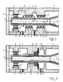
- FIG. 1 and 2 of the accompanying drawings show two examples of known and commonly used solutions, especially on turbomachines, to achieve this seal.
- Figures 1 and 2 there is shown an enclosure closed by walls 1, in which is placed a rotating shaft 2, supported in particular by a bearing 3 bearing.
- the bearing 3 is placed in a first compartment 4, supplied with oil by means known per se and not shown in the drawing, this oil ensuring in particular the lubrication and cooling of the elements of the bearing 3.
- the first compartment 4 is also provided means for evacuating the oil shown diagrammatically by a bore 5, connected for example to a recovery pump not shown in the drawing.
- the circulation of the oil is symbolized by the arrows f1.
- a seal 6 of the labyrinth type is mounted between said first compartment 4 and a second neighboring compartment 7 which must be protected from any oil entry.
- the seal 6 can, for example and as shown in Figure 1, be double and have two sets of wipers 8 cooperating with a lining 9 of the abradable type.
- Air pressurization is also ensured from an air inlet from the inside of the shaft 2.
- the air circulation is symbolized by the arrows f2.
- a cavity 10 has been formed which also has a drain hole 11 which makes it possible to drain the oil, each time the particular operating conditions bring the oil into contact with the seal 6 and risk cause oil leaks.
- a complementary deflector device 12 can be added to the first compartment 4 to constitute a barrier to the migration of oil. In certain applications, these known arrangements prove however to be insufficient to avoid any undesirable migration of oil to the second air compartment 7. The same difficulties are encountered in the other solution as shown in FIG. 2.
- a seal carbon 13 is mounted, in a manner known per se, between the shaft 2 and the partition wall 14 between the oil 4 and air 7 compartments.
- the seal 13 is notably associated with baffles 15 and with a oil recovery cavity 16 also provided with a drain 17 for evacuating any leaks.
- FR-A 2 131 797 also shows the use of a deflector in the vicinity of a lubricated bearing and associated with a seal of the labyrinth type.
- FR-A-2 388 181 shows the use of a sealing ring which expands radially under the effect of the centrifugal force and retracts diametrically by elasticity when stationary.
- GB-A- 1 450 553 and GB-A- 1 598 926 describe the principle of so-called "brush" seals comprising an external lining of tight flexible bristles.
- an enclosure bearing of the aforementioned kind is characterized in that the first compartment comprises at least one deflector screen mounted on the shaft, having the general shape of a disc and consisting of a rigid central part which supports a peripheral part made of flexible material of so that said screen is introduced into said first compartment through a bore of diameter less than the external diameter of the screen in operation.
- said deflector screen consists of a metal disc, the periphery of which is furnished with bristles of flexible material so that said bristles lie down when the screen is placed through the bore of the enclosure. and having sufficient rigidity to straighten and form a screen under the effect of centrifugal force.
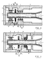
- a bearing enclosure produced in accordance with the invention firstly comprises known elements similar to those of the known bearing enclosure which has been previously described with reference to the figure 1.
- the same references are kept to designate these known elements.
- the walls 1 of the enclosure proper. It will be noted in particular that said walls 1 constitute a one-piece, non-removable assembly, the mounting of the various elements inside the enclosure must necessarily, in this type of application, be carried out by passing them through the bore of the pregnant.
- a seal 6 is also mounted between the first compartment 4 and a second neighboring compartment 7 which is only accessible to air.
- the seal 6 is in the example shown in Figure 3, as in the case of Figure 1, composed of wipers 8 and an abradable lining 9.
- the known rigid deflector 12, previously used according to FIG. 1 is replaced by a deflector screen 18 consisting of a rigid central part 18a, in particular made of metallic material, which supports a peripheral part 18b made of flexible material. During assembly, this flexible peripheral part 18b folds back to pass through the bore of the bearing enclosure, in particular the bore of the seal 6 separating the compartments 7 and 4.
- this flexible peripheral part 18b of the deflector screen 18 straightens, its external diameter then being much greater than that of the bore at the joint 6.
- the screen deflector 18 mounted integrally on the shaft 2 undergoes the effect of centrifugal force and the peripheral part 18b stiffens, constituting in particular an impassable oil barrier used for the lubrication and cooling of the bearing.
- said flexible peripheral portion 18b of the deflector screen 18 consists of flexible rods or bristles 18c, secured to the rigid central portion 18a, thus forming a screen disc 18. These hairs 18c can be radial or not.
- the choice of the material constituting the bristles is determined as a function of the conditions of use, in particular the resistance to the temperatures provided, the compatibility with the oil used, mechanical characteristics of sufficient strength, of flexibility allowing passage through the bore of the seal. the enclosure and sufficient rigidity to form a screen, in rotation. These criteria also make it possible to determine the implantation density of the bristles and the width of the screen 18.
- known materials of synthetic or metallic type are used. Instead of bristles, you can, for example, also use plastic strips providing the same results.
- the application of the deflector screen device 18 can also be made to a bearing enclosure comprising a carbon type seal, as previously described with reference to FIG. 2.
- the device comprises, in addition to the deflector screen 18, another deflector screen 19, also placed in the first compartment 4, on the other side bearing 3.
- this deflector screen 19 also includes a rigid central part 19a and a flexible peripheral part 19b, constituted in the example shown of bristles 19c secured to the central part 19a.
- the screen 19 prevents an accumulation of oil in this part of the compartment 4, but on the contrary brings the oil back to the bearing 3.
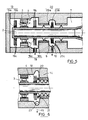
- the seal 6 arranged between the compartments 4 and 7 is in two parts and that a cavity 10 separates the two stages of the joint, as in the example shown in FIG. 1, it is also possible, in accordance with the invention, to add on the shaft 2 a deflector screen 20, at the level of said cavity 10, as shown in FIG. 5.
- the deflector screen 20 in accordance with the invention also consists of a rigid central part 20a and a flexible peripheral part 20b, constituted, for example and as before, of bristles 20c. In this case, maximum sealing efficiency is obtained, avoiding any risk of oil migration to the second compartment 7 of the bearing enclosure.
- the transverse wall 14 of separation between the two enclosure compartments 4 and 7 comprises on the side of the first compartment 4, at the internal radial edge, a small border 21 comprising a circular channel 22, which prevents, in particular when the shaft 2 is in vertical position, the oil to flow along the bore.
- the orifice 23, for evacuation and aspiration of oil arranged at the low point of the first compartment 4 is oriented tangentially.
- the orifice 23 is also arranged so as to suck up the oil which collects in the channel 22, when the shaft is in the vertical position.
Landscapes
- Engineering & Computer Science (AREA)
- General Engineering & Computer Science (AREA)
- Mechanical Engineering (AREA)
- Sealing Using Fluids, Sealing Without Contact, And Removal Of Oil (AREA)
- Sealing Of Bearings (AREA)
Description
- La présente invention concerne une enceinte de palier, notamment de turbomachine, munie d'un joint d'étanchéité associé à un dispositif d'écran déflecteur.
- Dans une enceinte de palier, notamment de turbomachine, il est courant de ménager deux compartiments, l'un comportant un roulement et dans lequel est acheminée de l'huile, notamment en vue de la lubrification et du refroidissement dudit roulement et l'autre dans lequel est établie une pression d'air et qui communique avec d'autres enceintes à air de la machine. Il est important d'éviter toute fuite d'huile à partir du compartiment huile vers le compartiment à air et il est par conséquent habituel de prévoir dans ce cas des moyens d'étanchéité entre les deux compartiments. Les figures 1 et 2 des dessins annexés montrent deux exemples des solutions connues et couramment utilisées, notamment sur turbomachines, pour réaliser cette étanchéité. Sur les figures 1 et 2, on a ainsi représenté une enceinte fermée par des parois 1, dans laquelle est placée un arbre tournant 2, supporté notamment par un roulement 3 de palier. Le roulement 3 est placé dans un premier compartiment 4, alimenté en huile par des moyens connus en soi et non représentés au dessin, cette huile assurant notamment la lubrification et le refroidissement des éléments du roulement de palier 3. Le premier compartiment 4 est également muni de moyens d'évacuation de l'huile schématisés par un perçage 5, relié par exemple à une pompe de récupération non représentée au dessin. La circulation de l'huile est symbolisée par les flèches f1. Selon la solution représentée sur la figure 1, un joint 6 du type à labyrinthe est monté entre ledit premier compartiment 4 et un deuxième compartiment 7 voisin qui doit être préservé de toute entrée d'huile. Le joint 6 peut, par exemple et comme représenté sur la figure 1, être double et comporter deux séries de léchettes 8 coopérant avec une garniture 9 de type abradable. Une pressurisation d'air est en outre assurée à partir d'une arrivée d'air par l'intérieur de l'arbre 2. La circulation d'air est symbolisée par les flèches f2. Entre les deux étages de joint 6, a été ménagée une cavité 10 qui comporte également un trou d'évacuation 11 qui permet de drainer l'huile, chaque fois que les conditions particulières de fonctionnement amènent l'huile au contact du joint 6 et risquent d'occasionner des fuites d'huile. Un dispositif complémentaire de déflecteur 12 peut être adjoint dans le premier compartiment 4 pour constituer un barrage à la migration d'huile. Dans certaines applications, ces dispositions connues se révèlent toutefois insuffisantes pour éviter toute migration indésirable d'huile vers le deuxième compartiment à air 7. Les mêmes difficultés sont rencontrées dans l'autre solution comme représentée sur la figure 2. Dans ce cas, un joint carbone 13 est monté, de manière connue en soi, entre l'arbre 2 et la paroi de séparation 14 entre les compartiments à l'huile 4 et à l'air 7. Le joint 13 est notamment associé à des chicanes 15 et à une cavité 16 de récupération d'huile également munie d'un drain 17 d'évacuation des fuites éventuelles. Notamment, chaque fois que la pressurisation d'air dans le premier compartiment 4 est insuffisamment contrôlée par suite de variations dans les conditions de fonctionnement ou de diverses défaillances, l'efficacité de l'étanchéité primordiale entre les compartiments 4 et 7 est remise en cause.
- Par ailleurs, FR-A 2 131 797 montre également l'utilisation d'un déflecteur au voisinage d'un roulement lubrifié et associé à un joint du type à labyrinthe. FR-A-2 388 181 montre l'utilisation d'une bague d'étanchéité qui se dilate radialement sous l'effet de la force centrifuge et se rétracte diamétralement par élasticité, à l'arrêt.
GB-A- 1 450 553 et GB-A- 1 598 926 décrivent le principe de joints d'étanchéité dits "à brosse" comportant une garniture externe de poils souples serrés. Une solution améliorée permettant notamment d'assurer une meilleure efficacité de l'étanchéité à l'encontre des migrations d'huile tant en procurant une solution simple aux problèmes de montage est obtenue par la mise en oeuvre de la présente invention, selon laquelle une enceinte de palier du genre précité est caractérisée en ce que le premier compartiment comporte au moins un écran déflecteur monté sur l'arbre, présentant la forme générale d'un disque et constitué d'une partie centrale rigide qui supporte une partie périphérique en matériau souple de manière que ledit écran est introduit dans ledit premier compartiment à travers un alésage de diamètre inférieur au diamètre externe de l'écran en fonctionnement. - Avantageusement, ledit écran déflecteur est constitué d'un disque métallique dont la périphérie est garnie de poils en matériau souple de manière à ce que lesdits poils se couchent lors de la mise en place de l'écran à travers l'alésage de l'enceinte et présentant une rigidité suffisante pour se redresser et former écran sous l'effet de la force centrifuge.
- Divers aménagements complémentaires peuvent également être apportés à l'invention. D'autres caractéristiques et avantages de l'invention seront mieux compris à la lecture de la description qui va suivre d'un mode de réalisation de l'invention et de quelques variantes qui lui sont éventuellement applicables, en référence aux dessins annexés sur lesquels :
- la figure 1 représente, selon une vue schématique en coupe longitudinale par un plan passant par l'axe de rotation de l'arbre, une enceinte de palier comportant des moyens d'étanchéité connus et qui a fait précédemment l'objet d'une description ;
- la figure 2 représente, selon une vue analogue à celle de la figure 1, un autre exemple connu de réalisation d'une enceinte de palier comportant d'autres moyens d'étanchéité connus et qui a fait également et précédemment l'objet d'une description ;
- la figure 3 représente, selon une vue schématique analogue à celles des figures 1 et 2, une enceinte de palier comportant un écran déflecteur, selon un mode de réalisation de l'invention et associé à des moyens connus d'étanchéité analogues à ceux de la figure 1 ;
- la figure 4 représente, selon une vue schématique analogue à celle des figures 1 à 3, une enceinte de palier comportant un écran déflecteur, analogue à celui de la figure 3 et associé à des moyens connus d'étanchéité anlogues à ceux de la figure 2 ;
- la figure 5 représente, selon une vue schématique analogue à celle des figures 1 à 4, une enceinte de palier comportant plusieurs écrans déflecteurs, analogues à celui des figures 3 ou 4 et associé à des moyens connus d'étanchéité analogues à ceux de la figure 1 ;
- la figure 6 montre un détail de réalisation des moyens d'évacuation d'huile qui peuvent être associés à un écran déflecteur conforme à l'invention, selon l'une des figures 3 à 5
- Une enceinte de palier réalisée conformément à l'invention, telle qu'elle est représentée sur la figure 3, comporte tout d'abord des éléments connus similaires à ceux de l'enceinte de palier connue qui a été précédemment décrite en référence à la figure 1. Les mêmes références sont conservées pour désigner ces éléments connus. On retrouve ainsi notamment les parois 1 de l'enceinte proprement dite. On notera particulièrement que lesdites parois 1 constituent un ensemble monobloc, non démontable, le montage des divers éléments à l'intérieur de l'enceinte devant obligatoirement, dans ce type d'applications, être effectué en les passant par l'alésage de l'enceinte. On retrouve également l'arbre tournant 2, supporté par le roulement 3 de palier, lui-même placé dans un premier compartiment 4, toujours alimenté en huile et muni de moyens d'évacuation 5 de cette huile qui circule suivant les flèches f1. Un joint d'étanchéité 6 est également monté entre le premier compartiment 4 et un second compartiment 7 voisin qui n'est accessible qu'à l'air. Le joint 6 est dans l'exemple représenté sur la figure 3, comme dans le cas de la figure 1, composé de léchettes 8 et d'une garniture abradable 9. Par contre, et de manière remarquable, conforme à l'invention, le déflecteur rigide 12 connu, précédemment utilisé selon la figure 1, est remplacé par un écran déflecteur 18 constitué d'une partie centrale 18a rigide, notamment en matériau métallique, qui supporte une partie périphérique 18b en matériau souple. Lors du montage, cette partie périphérique 18b souple se replie pour traverser l'alésage de l'enceinte de palier, notamment l'alésage du joint 6 séparant les compartiments 7 et 4. En arrivant dans le premier compartiment 4, cette partie périphérique souple 18b de l'écran déflecteur 18 se redresse, son diamètre externe étant alors nettement supérieur à celui de l'alésage au niveau du joint 6. Lorsque l'arbre 2 est entraîné en rotation, l'écran déflecteur 18 monté solidairement sur l'arbre 2, subit l'effet de la force centrifuge et la partie périphérique 18b se rigidifie, constituant notamment un barrage infranchissable à l'huile utilisée pour la lubrification et le refroidissement du roulement. Dans l'exemple de réalisation représenté sur la figure 3, ladite partie périphérique souple 18b de l'écran déflecteur 18 est constituée de tiges souples ou poils 18c, solidarisés à la partie centrale rigide 18a, formant ainsi un disque d'écran 18. Ces poils 18c peuvent être radiaux ou non.
- Le choix du matériau constituant les poils est déterminé en fonction des conditions d'utilisation notamment la tenue aux températures prévues, la compatibilité avec l'huile utilisée, des caractéristiques mécaniques de résistance suffisante, de souplesse permettant le passage dans l'alésage du joint de l'enceinte et de rigidité suffisante pour former écran, en rotation. Ces critères permettent également de déterminer la densité d'implantation des poils et la largeur de l'écran 18. On utilise ainsi notamment des matériaux connus de type synthétique ou métallique. Au lieu de poils, on peut, par exemple, utiliser également des lamelles en matériau plastique procurant les mêmes résultats.
- Selon la figure 4, l'application du dispositif à écran déflecteur 18 peut également être faite à une enceinte de palier comportant un joint d'étanchéité de type carbone, telle qu'elle a été précédemment décrite en référence à la figure 2.
- Selon une variante de réalisation, représentée sur la figure 5, le dispositif comporte, en plus de l'écran déflecteur 18, un autre écran déflecteur 19, placé également dans le premier compartiment 4, de l'autre côté du roulement 3.
- De manière similaire à l'écran 18, cet écran déflecteur 19 comporte également une partie centrale rigide 19a et une partie périphérique souple 19b, constituée dans l'exemple représenté de poils 19c solidarisés à la partie centrale 19a. L'écran 19 évite une accumulation d'huile dans cette partie du compartiment 4, mais au contraire ramène l'huile vers le roulement 3. Lorsque le joint d'étanchéité 6 disposé entre les compartiments 4 et 7 est en deux parties et qu'une cavité 10 sépare les deux étages de joint, comme dans l'exemple représenté sur la figure 1, on peut également conformément à l'invention, ajouter sur l'arbre 2 un écran déflecteur 20, au niveau de ladite cavité 10, comme représenté sur la figure 5. L'écran déflecteur 20 conformément à l'invention, se compose également d'une partie centrale rigide 20a et d'une partie périphérique souple 20b, constituée, par exemple et comme précédemment, de poils 20c. Dans ce cas, une efficacité maximale de l'étanchéité est obtenue, évitant tout risque de migration d'huile vers le deuxième compartiment 7 de l'enceinte de palier.
- Quelques dispositions complémentaires concernant la récupération et les évacuations de l'huile dans le premier compartiment 4, notamment telles que représentées sur la figure 6, permettent encore d'améliorer l'efficacité du dispositif. Ainsi, la paroi transversale 14 de séparation entre les deux compartiments 4 et 7 d'enceinte comporte du côté du premier compartiment 4, au bord radial interne, une petite bordure 21 comportant une rigole circulaire 22, ce qui empêche, notamment lorsque l'arbre 2 est en position verticale, l'huile de s'écouler le long de l'alésage. Afin d'utiliser l'énergie cinétique communiquée à l'huile par l'écran déflecteur 18 en rotation, l'orifice 23, d'évacuation et d'aspiration d'huile aménagée au point bas du premier compartiment 4 est orienté tangentiellement. L'orifice 23 est en outre disposé de manière à aspirer l'huile qui se rassemble dans la rigole 22, lorsque l'arbre est en position verticale.
Claims (5)
Applications Claiming Priority (2)
| Application Number | Priority Date | Filing Date | Title |
|---|---|---|---|
| FR8814914 | 1988-11-17 | ||
| FR8814914A FR2639073B1 (fr) | 1988-11-17 | 1988-11-17 | Enceinte de palier comportant un ecran deflecteur |
Publications (2)
| Publication Number | Publication Date |
|---|---|
| EP0369878A1 EP0369878A1 (fr) | 1990-05-23 |
| EP0369878B1 true EP0369878B1 (fr) | 1992-06-10 |
Family
ID=9371915
Family Applications (1)
| Application Number | Title | Priority Date | Filing Date |
|---|---|---|---|
| EP89403134A Expired - Lifetime EP0369878B1 (fr) | 1988-11-17 | 1989-11-15 | Enceinte de palier comportant un écran déflecteur |
Country Status (3)
| Country | Link |
|---|---|
| EP (1) | EP0369878B1 (fr) |
| DE (1) | DE68901762T2 (fr) |
| FR (1) | FR2639073B1 (fr) |
Cited By (2)
| Publication number | Priority date | Publication date | Assignee | Title |
|---|---|---|---|---|
| US6376828B1 (en) | 1998-10-07 | 2002-04-23 | E Ink Corporation | Illumination system for nonemissive electronic displays |
| US6473072B1 (en) | 1998-05-12 | 2002-10-29 | E Ink Corporation | Microencapsulated electrophoretic electrostatically-addressed media for drawing device applications |
Families Citing this family (3)
| Publication number | Priority date | Publication date | Assignee | Title |
|---|---|---|---|---|
| JPH04504177A (ja) * | 1989-02-18 | 1992-07-23 | ステメ,オットー | 固着具 |
| DE3940890C2 (de) * | 1989-12-11 | 2000-07-20 | Bernhard Weik | Lagerausbildung |
| US6640933B2 (en) * | 2001-07-10 | 2003-11-04 | Rolls Royce Corporation | Lubrication system for a bearing |
Citations (1)
| Publication number | Priority date | Publication date | Assignee | Title |
|---|---|---|---|---|
| FR2388181A1 (fr) * | 1977-04-20 | 1978-11-17 | Rolls Royce | Joint d'etancheite pour arbres rotatifs concentriques |
Family Cites Families (7)
| Publication number | Priority date | Publication date | Assignee | Title |
|---|---|---|---|---|
| US2248405A (en) * | 1938-05-05 | 1941-07-08 | Master Electric Co | Slinger ring |
| GB633181A (en) * | 1947-04-10 | 1949-12-12 | Carl Andermatt | Improvements in or relating to the bearings of high-speed atomizer disc shafts |
| US3259442A (en) * | 1965-03-25 | 1966-07-05 | Morgan Construction Co | Roll neck bearing seal |
| FR2131797B1 (fr) * | 1971-03-03 | 1975-02-21 | Snecma | |
| IT1022287B (it) * | 1973-09-27 | 1978-03-20 | Gelenkwellenbau Gmbh | Albero cardanico |
| GB1450553A (en) * | 1973-11-23 | 1976-09-22 | Rolls Royce | Seals and a method of manufacture thereof |
| GB1598926A (en) * | 1978-05-24 | 1981-09-23 | Rolls Royce | Brush seals |
-
1988
- 1988-11-17 FR FR8814914A patent/FR2639073B1/fr not_active Expired - Lifetime
-
1989
- 1989-11-15 EP EP89403134A patent/EP0369878B1/fr not_active Expired - Lifetime
- 1989-11-15 DE DE1989601762 patent/DE68901762T2/de not_active Expired - Fee Related
Patent Citations (1)
| Publication number | Priority date | Publication date | Assignee | Title |
|---|---|---|---|---|
| FR2388181A1 (fr) * | 1977-04-20 | 1978-11-17 | Rolls Royce | Joint d'etancheite pour arbres rotatifs concentriques |
Cited By (3)
| Publication number | Priority date | Publication date | Assignee | Title |
|---|---|---|---|---|
| US6473072B1 (en) | 1998-05-12 | 2002-10-29 | E Ink Corporation | Microencapsulated electrophoretic electrostatically-addressed media for drawing device applications |
| US6738050B2 (en) | 1998-05-12 | 2004-05-18 | E Ink Corporation | Microencapsulated electrophoretic electrostatically addressed media for drawing device applications |
| US6376828B1 (en) | 1998-10-07 | 2002-04-23 | E Ink Corporation | Illumination system for nonemissive electronic displays |
Also Published As
| Publication number | Publication date |
|---|---|
| DE68901762T2 (de) | 1993-01-07 |
| FR2639073B1 (fr) | 1990-12-21 |
| DE68901762D1 (de) | 1992-07-16 |
| EP0369878A1 (fr) | 1990-05-23 |
| FR2639073A1 (fr) | 1990-05-18 |
Similar Documents
| Publication | Publication Date | Title |
|---|---|---|
| EP3137755B1 (fr) | Module de turbomachine comportant un carter autour d'un equipement avec un capot de recuperation d'huile de lubrification | |
| EP0270444B1 (fr) | Système de lubrification pour démarreur de turbomachine | |
| FR2695162A1 (fr) | Ailette à système de refroidissement d'extrémité perfectionné. | |
| EP0369878B1 (fr) | Enceinte de palier comportant un écran déflecteur | |
| FR2704617A1 (fr) | Garniture d'étanchéité pour arbre tournant. | |
| FR3039589A1 (fr) | Etage de turbomachine, en particulier de turbine basse-pression | |
| EP3952941B1 (fr) | Pompe cardiaque a couplage magnetique et a flux inverse | |
| EP0097549B1 (fr) | Dispositif pour réaliser l'étanchéite d'un moteur immergeable et moteur s'y rapportant | |
| EP0491624B1 (fr) | Système d'étanchéité pour palier d'une machine, notamment d'une turbomachine | |
| FR2945331A1 (fr) | Virole pour stator de turbomoteur d'aeronef a fentes de dechargement mecanique d'aubes. | |
| EP3414475B1 (fr) | Dispositif d'etancheite ameliore, notamment en regard d'une contamination par des agents exterieurs | |
| FR2565295A1 (fr) | Pompe a vide rotative etanchee dans l'huile | |
| CA2606056C (fr) | Systeme d'etancheite entre deux arbres tournants coaxiaux | |
| EP2986821B1 (fr) | Pompe à vide rotative à palettes | |
| FR2543229A1 (fr) | Dispositif pour la compensation hydrostatique de pompes et moteurs hydrauliques du type a engrenage | |
| FR2588635A1 (fr) | Support d'arbre a palier etanche | |
| FR3066533B1 (fr) | Ensemble d'etancheite pour une turbomachine | |
| FR3021075B1 (fr) | Compresseur a spirales | |
| JP6321922B2 (ja) | 密封装置 | |
| EP3810902A2 (fr) | Joint d'etancheite a labyrinthe pour une turbomachine d'aeronef | |
| FR2697598A1 (fr) | Dispositif de protection contre l'entrée de particules et de polluants solides. | |
| FR3049980A1 (fr) | Ensemble de turbomachine comportant un systeme de deviation de fluide d'ecoulement entre une enceinte dudit fluide et un dispositif d'etancheite | |
| FR3075252A1 (fr) | Ensemble d'etancheite | |
| FR3161918A1 (fr) | Carter annulaire de recuperation d’huile pour une turbomachine, et module d’echappement comprenant un tel carter | |
| FR3136261A1 (fr) | Pompe à vide verticale |
Legal Events
| Date | Code | Title | Description |
|---|---|---|---|
| PUAI | Public reference made under article 153(3) epc to a published international application that has entered the european phase |
Free format text: ORIGINAL CODE: 0009012 |
|
| 17P | Request for examination filed |
Effective date: 19891127 |
|
| AK | Designated contracting states |
Kind code of ref document: A1 Designated state(s): DE FR GB |
|
| 17Q | First examination report despatched |
Effective date: 19911128 |
|
| GRAA | (expected) grant |
Free format text: ORIGINAL CODE: 0009210 |
|
| AK | Designated contracting states |
Kind code of ref document: B1 Designated state(s): DE FR GB |
|
| REF | Corresponds to: |
Ref document number: 68901762 Country of ref document: DE Date of ref document: 19920716 |
|
| GBT | Gb: translation of ep patent filed (gb section 77(6)(a)/1977) | ||
| PLBE | No opposition filed within time limit |
Free format text: ORIGINAL CODE: 0009261 |
|
| STAA | Information on the status of an ep patent application or granted ep patent |
Free format text: STATUS: NO OPPOSITION FILED WITHIN TIME LIMIT |
|
| 26N | No opposition filed | ||
| REG | Reference to a national code |
Ref country code: GB Ref legal event code: IF02 |
|
| REG | Reference to a national code |
Ref country code: FR Ref legal event code: TP Ref country code: FR Ref legal event code: CD |
|
| REG | Reference to a national code |
Ref country code: FR Ref legal event code: CD |
|
| PGFP | Annual fee paid to national office [announced via postgrant information from national office to epo] |
Ref country code: DE Payment date: 20071113 Year of fee payment: 19 |
|
| PGFP | Annual fee paid to national office [announced via postgrant information from national office to epo] |
Ref country code: GB Payment date: 20071029 Year of fee payment: 19 Ref country code: FR Payment date: 20071029 Year of fee payment: 19 |
|
| GBPC | Gb: european patent ceased through non-payment of renewal fee |
Effective date: 20081115 |
|
| REG | Reference to a national code |
Ref country code: FR Ref legal event code: ST Effective date: 20090731 |
|
| PG25 | Lapsed in a contracting state [announced via postgrant information from national office to epo] |
Ref country code: DE Free format text: LAPSE BECAUSE OF NON-PAYMENT OF DUE FEES Effective date: 20090603 |
|
| PG25 | Lapsed in a contracting state [announced via postgrant information from national office to epo] |
Ref country code: GB Free format text: LAPSE BECAUSE OF NON-PAYMENT OF DUE FEES Effective date: 20081115 |
|
| PG25 | Lapsed in a contracting state [announced via postgrant information from national office to epo] |
Ref country code: FR Free format text: LAPSE BECAUSE OF NON-PAYMENT OF DUE FEES Effective date: 20081130 |