EP0369904B1 - Von einem Schnurführungsbügel gesteuerte Angelwinde - Google Patents
Von einem Schnurführungsbügel gesteuerte Angelwinde Download PDFInfo
- Publication number
- EP0369904B1 EP0369904B1 EP89420441A EP89420441A EP0369904B1 EP 0369904 B1 EP0369904 B1 EP 0369904B1 EP 89420441 A EP89420441 A EP 89420441A EP 89420441 A EP89420441 A EP 89420441A EP 0369904 B1 EP0369904 B1 EP 0369904B1
- Authority
- EP
- European Patent Office
- Prior art keywords
- lever
- guide tube
- recuperator
- pivot
- disc
- Prior art date
- Legal status (The legal status is an assumption and is not a legal conclusion. Google has not performed a legal analysis and makes no representation as to the accuracy of the status listed.)
- Expired - Lifetime
Links
- 230000007246 mechanism Effects 0.000 claims description 5
- 230000006835 compression Effects 0.000 claims description 4
- 238000007906 compression Methods 0.000 claims description 4
- 238000011084 recovery Methods 0.000 claims description 3
- 230000000694 effects Effects 0.000 claims description 2
- 230000000284 resting effect Effects 0.000 claims 2
- 238000005266 casting Methods 0.000 claims 1
- 210000000056 organ Anatomy 0.000 description 4
- 230000008901 benefit Effects 0.000 description 3
- 238000004519 manufacturing process Methods 0.000 description 2
- 230000009467 reduction Effects 0.000 description 2
- 208000031968 Cadaver Diseases 0.000 description 1
- 230000009471 action Effects 0.000 description 1
- 238000003780 insertion Methods 0.000 description 1
- 230000037431 insertion Effects 0.000 description 1
- 230000010355 oscillation Effects 0.000 description 1
- 238000009987 spinning Methods 0.000 description 1
Images


Classifications
-
- A—HUMAN NECESSITIES
- A01—AGRICULTURE; FORESTRY; ANIMAL HUSBANDRY; HUNTING; TRAPPING; FISHING
- A01K—ANIMAL HUSBANDRY; AVICULTURE; APICULTURE; PISCICULTURE; FISHING; REARING OR BREEDING ANIMALS, NOT OTHERWISE PROVIDED FOR; NEW BREEDS OF ANIMALS
- A01K89/00—Reels
- A01K89/01—Reels with pick-up, i.e. with the guiding member rotating and the spool not rotating during normal retrieval of the line
- A01K89/0108—Pick-up details
- A01K89/01081—Guiding members on rotor axially rearward of spool
- A01K89/01082—Guiding members shiftable on rotor
- A01K89/01083—Guiding members shiftable on rotor to wind position by rotor drive
Definitions
- the present invention relates to spinning fishing reels of the so-called reel or fixed drum type.
- Fixed reel fishing reels include a reel with a longitudinal axis mounted on the reel body and urged by means preventing its rotation about its axis relative to the reel body during the steps of recovering the wire.
- a recuperator is rotatably mounted along the axis of the coil, and is biased by a rotary drive mechanism.
- the recuperator comprises an external part offset laterally outside the reel and developing from the rear towards the front of the reel, the external recuperator part carrying a recuperator hoop pivotally mounted between a closed position and a position opened. In the closed position, the recuperator hoop occupies a transverse position in the vicinity of the spool wire reserve to guide the fishing line and wind it around the spool during the rotation of the recuperator actuated by the crank. In the open position, the roll bar is retracted laterally to release the fishing line and allow it to be launched.
- the recuperator hoop is returned by the action of a torsion spring to its closed position and can be locked in the open position.
- a trigger system automatically returns the roll bar from its open position to its closed position when the user actuates the recuperator in rotation around its axis, for example to wind the fishing line on the reel after a launching step .
- the object of the present invention is to propose a new arrangement of the triggering assembly, allowing a significant reduction in the cost of producing this triggering function, by reducing the number of parts required and by simplifying their production.
- the assembly operations during the manufacture of the reel are considerably facilitated, and do not require any particular skill of the operators. Assembly can be done by manual means only.
- the means used according to the invention to obtain this cost reduction are also particularly suited to the usual structure of reels, not upsetting the habits of fishermen, respecting ergonomics, not causing annoying oversizing, not disturbing the usual functions of the reel.
- the lever and the guide tube are two separate parts, hinged to each other by the first lever end and the rear end of the guide tube, the second end of the lever being held in abutment against the guide tube by the effect of the torque exerted on the lever by the spring and the guide tube.
- the articulation between the first end of the lever and the guide tube consists of a recess formed at the end of the lever, recess in which a spherical head formed at the end of the tube is inserted. guidance.
- the lever and the guide tube are completely integral with each other, for example made in one and the same piece.
- the pivot of the lever is a cylindrical lug secured to the lever, and being housed in a corresponding cylindrical hole in the recuperator.
- the lever is advantageously inserted in a housing comprising two walls perpendicular to its pivot of rotation and preventing the axial translation of the lever along its pivot; the guide tube is itself guided by the same two walls.
- one of the two walls of the housing is an attached wall after assembly of the mechanical parts in the housing, so that said assembly is simple and rapid.
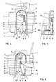
- Figures 1 to 3 a Known fishing reel of the fixed reel or drum type.
- this known type of reel comprises a body 1 on which a spool 2 is mounted along a longitudinal axis I - I.
- the spool 2 is stressed by means preventing its rotation about its longitudinal axis relative to the body reel during the wire recovery steps.
- a wire catcher 3 is rotatably mounted on the body 1 along the axis I - I of the coil, and can be rotated around its axis by a rotational drive mechanism not shown in the figures, comprising a crank user operated.
- the recuperator comprises a rotary base 4, integral with an external part 5 offset laterally outside the coil 2 and developing from the rear to the front of the coil, as shown in the figures.
- the front end 6 of the external recuperator part carries a recuperator hoop 7, articulated on the end 6 along an axis of radial rotation 8, perpendicular to the axis I - I of the coil.
- the hoop 7 has a disc-shaped base 9, the disc 9 swiveling on the axis 8.
- the hoop 7, and the disc 9 can take a so-called closed position, represented in FIG. 1, in which the hoop occupies a transverse position in the vicinity of the wire reserve 10 of the coil 2.
- the hoop 7 and the disc 9 can take a so-called open position, shown in Figure 3, in which the arch 7 is retracted laterally away from the spool and releases the fishing line.
- the closed position shown in Figure 1
- the fishing line passes through a groove 11 of the hoop 7, and the rotation of the hoop 7 driven by the recuperator 3 and the crank causes the fishing line to be wound up in the reserve of wire 10 of coil.
- the hoop 7 When the hoop 7 is in the open position, the fishing line can unwind freely outside the reserve 10, allowing for example a throwing operation.
- a holding mechanism maintains the arch 7 in both of the open and closed positions.
- the hoop disc 9 is biased by a compression spring 12, the force of which develops in a plane substantially perpendicular to the hoop axis 8 and is transmitted to the disc 9 in an articulation pivot 13.
- the pivot 13 allows the spring 12 to pivot relative to the disc 9 along an axis parallel to the hoop axis 8.
- the pivot 13 is positioned on the disc 9 in a so-called "intermediate" position, as shown in the figures, that is to say arranged in such a way that the torque of disc 9 around its axis 8 produced by the force of spring 12 on the pivot 13 cancels and changes direction in an intermediate position of the circular stroke between the two open and closed positions of the hoop 7.
- the torque produced by the spring 12 tends to keep the hoop in the position chosen.
- FIGS. 1 and 3 show the two extreme pivoting positions of the guide tube 14.
- the trigger device comprises a lever 16 pivotally mounted on the recuperator 3 along a longitudinal axis formed by a screw 17.
- the lever comprises a first end 19 intended to come into contact with a ramp 20 for integral triggering of the reel body 1, and a second end 21 intended to push the guide tube 14 towards its closed position shown in FIG. 1, beyond the point of torque inversion.
- a return spring 22 biases the lever 16 to keep it in abutment against the guide tube 14, thus preventing it from taking on any rotation of the recuperator 3 in any position liable to disturb the triggering and / or that it produce an unpleasant sound phenomenon.
- the mechanism of triggering requires the provision of a guide tube pivot axis 14, a trigger lever 16, a screw 17 forming the axis of rotation of the lever 16, and a return spring 22.
- the mounting of the device is relatively difficult, in particular because of the axial position of the screw 17, and requires the assembly of a relatively large number of parts.
- the reel of the present invention incorporates the main functional organs of the known reel.
- These known functional organs are listed in FIGS. 4 to 7 with the same reference numbers as in FIGS. 1 to 3.
- the known functional organs have the same shape as the corresponding organs known reels of Figures 1 to 3.
- These identical elements are the following body: reel 1, spool 2, base of recuperator 4, outer part 5 of recuperator, hoop 7 with its disc 9 journalled on an axis 8 disposed at the end 6 of the external part 5 of the recuperator, pivot 13 in the "intermediate" position forming an articulation at the end of a spring 12 guided by a guide tube 14.
- the difference lies in the structure of the recuperator triggering means.
- the trigger lever 16 comprises a first arm 160 extending in a transverse direction substantially parallel to the plane of the hoop disc 9, between a first end 31 of the lever and an intermediate portion 35 leverage.
- transverse direction is understood to mean a direction which is not parallel to the guide tube 14.
- the trigger lever 16 is mounted oscillating, in an intermediate zone of its first arm 160, around a lever pivot 30 substantially parallel to the axis of rotation 8 of the hoop disc 9. Its first end 31 is articulated at the rear end 32 of the guide tube 14. In this way, the lever 16 itself forms the pivot axis of the guide tube 14 relative to the recuperator, because the guide tube 14 doesn’t is not articulated directly on the recuperator.
- the second end 33 of the lever is supported on the side wall 34 of the guide tube 14, the lever having a general L-shape as shown in the figures.
- the spring 12 constitutes on the one hand a member for holding the arch 7 in the closed or open position, and simultaneously a member for return of the lever 16. This avoids the use of a return spring such as the spring 22 of Figures 1 to 3.
- the intermediate portion 35 of the lever comprises a radial finger 350 substantially perpendicular to the first arm 160 and developing inwardly of the reel. The free end of the radial finger 350 forms a bearing zone urged by the ramp 20 of the reel body 1.
- the articulation between the first end 31 of the lever 16 and the guide tube 14 consists of a recess formed at the end of the lever, recess in which is inserted a spherical head 36 formed at the end of the tube guide 14.
- the lever pivot 30 is a cylindrical lug secured to the lever 16, and being housed in a corresponding cylindrical hole in the recuperator 3.
- the lever 16 is inserted into a housing 37, kept with little clearance between two walls 38 and 39 perpendicular to its pivot 30, the two walls 38 and 39 preventing the translation of the lever 16 in the axis of its pivot 30.
- the guide tube 14 is itself also guided by the same two walls 38 and 39.
- the external wall 38 is an attached wall, which is adapted after mounting of the mechanical parts contained in the housing 37.
- the trigger lever 16 In the vicinity of the open position, and during at least part of the rotation stroke of the lever 16, the trigger lever 16 is supported on the guide tube 14, on the one hand by its first end 31, on the other leaves by its second end 33.
- the transverse distance E between the lever pivot 30 and its first end 31 produces, by the axial force exerted by the spring 12 and the guide tube 14, a torque of rotation of the lever 16 in the direction represented by the arrow 42, maintaining the second end 33 of the lever 16 pressing against the wall 34 of the guide tube 14.
- the lever 16 follows the oscillations of the guide tube 14, and the spring 12 constitutes in itself a means of returning the trigger lever 16.
- This possibility can be advantageous in reels in which the disc 9 has a large dimension relative to the length of the guide tube 14, so that the angular movement of the guide tube 14 is relatively large.
- This embodiment also makes it possible to produce the guide tube 14 in a material different from that constituting the lever 16.
- the guide tube 14 can be made of a material with a low coefficient of friction, to promote the sliding of the spring 12 in the tube and the pivoting of the tube 14 around the pivot formed by the first end 31 of the lever 16; the lever 16 can on the other hand be made of a mechanically resistant material, to withstand the mechanical stresses to which it is submitted.
- This embodiment also has the advantage of facilitating the mounting of the reel, the introduction of two separate parts 14 and 16 into the housing being faster than the insertion of a single part forming a lever 16 and a tube. guide 14.
- FIG. 7 a second embodiment, represented in FIG. 7, in which the guide tube 14 and the lever 16 are completely integral with one another.
- the guide tube 14 and the lever 16 are then necessarily integral over their entire pivoting stroke around the pivot 30.
Landscapes
- Life Sciences & Earth Sciences (AREA)
- Environmental Sciences (AREA)
- Animal Husbandry (AREA)
- Biodiversity & Conservation Biology (AREA)
Claims (7)
dadurch gekennzeichnet, daß:
Applications Claiming Priority (2)
| Application Number | Priority Date | Filing Date | Title |
|---|---|---|---|
| FR8815207 | 1988-11-17 | ||
| FR8815207A FR2638939B1 (fr) | 1988-11-17 | 1988-11-17 | Moulinet de peche a commande d'arceau perfectionnee |
Publications (2)
| Publication Number | Publication Date |
|---|---|
| EP0369904A1 EP0369904A1 (de) | 1990-05-23 |
| EP0369904B1 true EP0369904B1 (de) | 1992-06-10 |
Family
ID=9372115
Family Applications (1)
| Application Number | Title | Priority Date | Filing Date |
|---|---|---|---|
| EP89420441A Expired - Lifetime EP0369904B1 (de) | 1988-11-17 | 1989-11-15 | Von einem Schnurführungsbügel gesteuerte Angelwinde |
Country Status (2)
| Country | Link |
|---|---|
| EP (1) | EP0369904B1 (de) |
| FR (1) | FR2638939B1 (de) |
Families Citing this family (3)
| Publication number | Priority date | Publication date | Assignee | Title |
|---|---|---|---|---|
| FR2664793B1 (fr) * | 1990-07-20 | 1992-10-16 | Mitchell Sports | Moulinet de peche a verrouillage de bobine et de recuperateur. |
| JPH08298902A (ja) * | 1995-05-09 | 1996-11-19 | Shimano Inc | スピニングリールのベール姿勢切り換え装置 |
| SG119211A1 (en) | 2003-02-05 | 2006-02-28 | Shimano Kk | Rotor for a spinning reel |
Family Cites Families (2)
| Publication number | Priority date | Publication date | Assignee | Title |
|---|---|---|---|---|
| FR2414869A1 (fr) * | 1978-01-20 | 1979-08-17 | Mitchell Sa | Moulinet de peche |
| JPH0246703Y2 (de) * | 1985-05-09 | 1990-12-10 |
-
1988
- 1988-11-17 FR FR8815207A patent/FR2638939B1/fr not_active Expired - Lifetime
-
1989
- 1989-11-15 EP EP89420441A patent/EP0369904B1/de not_active Expired - Lifetime
Also Published As
| Publication number | Publication date |
|---|---|
| EP0369904A1 (de) | 1990-05-23 |
| FR2638939B1 (fr) | 1991-02-01 |
| FR2638939A1 (fr) | 1990-05-18 |
Similar Documents
| Publication | Publication Date | Title |
|---|---|---|
| FR2819231A1 (fr) | Unite combinee de changement de vitesse et de commande de frein pour bicyclette | |
| EP0032091A2 (de) | Behälter für steife Produkte, wie z.B. Stäbchen, Bleistiftminen und dgl. | |
| FR2695616A1 (fr) | Frein de bicyclette à leviers articulés. | |
| FR2811007A1 (fr) | Charniere avec arret de porte integre | |
| FR2787822A1 (fr) | Agencement de poignee pour une piece de carrosserie mobile d'un vehicule automobile | |
| WO1995006902A1 (fr) | Montre-bracelet a bracelet interchangeable | |
| EP0884219B1 (de) | Bewegbare Trittstufe für ein Fahrzeug | |
| EP2387880A1 (de) | Angelrute zum Wurfangeln | |
| EP0066322B1 (de) | Bremsvorrichtung eines metallischen Messbandes | |
| EP1079721A1 (de) | Wischmaterialspender | |
| EP0369904B1 (de) | Von einem Schnurführungsbügel gesteuerte Angelwinde | |
| CH616511A5 (en) | Spring hinge for spectacles | |
| FR2745695A1 (fr) | Dispositif d'articulation d'une poignee de sac et bagages a main similaires | |
| FR2664793A1 (fr) | Moulinet de peche a verrouillage de bobine et de recuperateur. | |
| EP1816294B1 (de) | Federgehäuse einer Fallschutzvorrichtung für Rollläden mit vertikaler Bewegungsrichtung | |
| FR2864114A1 (fr) | Porte de tambour rotatif, notamment pour machine a laver et ou secher le linge | |
| EP1321608B1 (de) | Schlüssel mit einziehbarem Schlüsselschaft | |
| FR2669371A1 (fr) | Dispositif a tige permettant une lente rotation. | |
| FR2777158A1 (fr) | Moulinet de peche a verrouillage selectif de bobine et de recuperateur | |
| FR2676887A1 (fr) | Moulinet de peche a recuperateur muni d'un dispositif de verrouillage et de rappel perfectionne. | |
| EP0205372B1 (de) | Vorrichtung zum Führen eines Teils eines Kabels oder eines Bündels von Kabeln zur Verbindung zwischen einem feststehenden Gehäuse und einem gelenkigen beweglichen Teil | |
| FR2636106A1 (fr) | Dispositif de commande par cable en particulier pour derailleur de bicyclette | |
| FR2818792A3 (fr) | Interrupteur auto-adaptable, particulierement pour le controle des feux de stop d'un vehicule automobile | |
| FR2764498A1 (fr) | Dispositif de limitation de la rotation sur un tour du tambour d'un appareil distributeur de papier essuie-mains | |
| FR2487637A1 (fr) | Moulinet de peche |
Legal Events
| Date | Code | Title | Description |
|---|---|---|---|
| PUAI | Public reference made under article 153(3) epc to a published international application that has entered the european phase |
Free format text: ORIGINAL CODE: 0009012 |
|
| AK | Designated contracting states |
Kind code of ref document: A1 Designated state(s): GB IT |
|
| 17P | Request for examination filed |
Effective date: 19901001 |
|
| 17Q | First examination report despatched |
Effective date: 19911025 |
|
| RAP3 | Party data changed (applicant data changed or rights of an application transferred) |
Owner name: MITCHELL SPORTS |
|
| GRAA | (expected) grant |
Free format text: ORIGINAL CODE: 0009210 |
|
| AK | Designated contracting states |
Kind code of ref document: B1 Designated state(s): GB IT |
|
| PG25 | Lapsed in a contracting state [announced via postgrant information from national office to epo] |
Ref country code: IT Free format text: LAPSE BECAUSE OF FAILURE TO SUBMIT A TRANSLATION OF THE DESCRIPTION OR TO PAY THE FEE WITHIN THE PRE;WARNING: LAPSES OF ITALIAN PATENTS WITH EFFECTIVE DATE BEFORE 2007 MAY HAVE OCCURRED AT ANY TIME BEFORE 2007. THE CORRECT EFFECTIVE DATE MAY BE DIFFERENT FROM THE ONE RECORDED.SCRIBED TIME-LIMIT Effective date: 19920610 |
|
| GBT | Gb: translation of ep patent filed (gb section 77(6)(a)/1977) | ||
| PLBE | No opposition filed within time limit |
Free format text: ORIGINAL CODE: 0009261 |
|
| STAA | Information on the status of an ep patent application or granted ep patent |
Free format text: STATUS: NO OPPOSITION FILED WITHIN TIME LIMIT |
|
| 26N | No opposition filed | ||
| PG25 | Lapsed in a contracting state [announced via postgrant information from national office to epo] |
Ref country code: GB Effective date: 19931115 |
|
| GBPC | Gb: european patent ceased through non-payment of renewal fee |
Effective date: 19931115 |