EP0369905A1 - Backofen mit Doppeltür - Google Patents
Backofen mit Doppeltür Download PDFInfo
- Publication number
- EP0369905A1 EP0369905A1 EP89420442A EP89420442A EP0369905A1 EP 0369905 A1 EP0369905 A1 EP 0369905A1 EP 89420442 A EP89420442 A EP 89420442A EP 89420442 A EP89420442 A EP 89420442A EP 0369905 A1 EP0369905 A1 EP 0369905A1
- Authority
- EP
- European Patent Office
- Prior art keywords
- enclosure
- inner plate
- wall
- door
- seal
- Prior art date
- Legal status (The legal status is an assumption and is not a legal conclusion. Google has not performed a legal analysis and makes no representation as to the accuracy of the status listed.)
- Granted
Links
- 230000002093 peripheral effect Effects 0.000 claims abstract description 8
- 239000011521 glass Substances 0.000 claims description 7
- 230000001681 protective effect Effects 0.000 claims description 5
- 238000007789 sealing Methods 0.000 claims description 4
- 230000010355 oscillation Effects 0.000 claims 1
- XLYOFNOQVPJJNP-UHFFFAOYSA-N water Substances O XLYOFNOQVPJJNP-UHFFFAOYSA-N 0.000 description 9
- 238000001816 cooling Methods 0.000 description 4
- 238000004140 cleaning Methods 0.000 description 3
- 238000010411 cooking Methods 0.000 description 3
- 239000012780 transparent material Substances 0.000 description 3
- 238000009833 condensation Methods 0.000 description 2
- 230000005494 condensation Effects 0.000 description 2
- 238000006073 displacement reaction Methods 0.000 description 2
- 239000007789 gas Substances 0.000 description 2
- 239000000463 material Substances 0.000 description 2
- 239000000243 solution Substances 0.000 description 2
- OKTJSMMVPCPJKN-UHFFFAOYSA-N Carbon Chemical compound [C] OKTJSMMVPCPJKN-UHFFFAOYSA-N 0.000 description 1
- 238000009825 accumulation Methods 0.000 description 1
- 230000005465 channeling Effects 0.000 description 1
- 238000002485 combustion reaction Methods 0.000 description 1
- 230000002950 deficient Effects 0.000 description 1
- 230000000694 effects Effects 0.000 description 1
- 238000002347 injection Methods 0.000 description 1
- 239000007924 injection Substances 0.000 description 1
- 230000005855 radiation Effects 0.000 description 1
- 238000009834 vaporization Methods 0.000 description 1
- 230000008016 vaporization Effects 0.000 description 1
- 230000002747 voluntary effect Effects 0.000 description 1
Images

Classifications
-
- F—MECHANICAL ENGINEERING; LIGHTING; HEATING; WEAPONS; BLASTING
- F24—HEATING; RANGES; VENTILATING
- F24C—DOMESTIC STOVES OR RANGES ; DETAILS OF DOMESTIC STOVES OR RANGES, OF GENERAL APPLICATION
- F24C15/00—Details
- F24C15/02—Doors specially adapted for stoves or ranges
- F24C15/04—Doors specially adapted for stoves or ranges with transparent panels
Definitions
- the present invention relates to ovens, such as ovens for cooking food, provided with an opening closable by a hinged door.
- the door In traditional ovens, the door is a rigid frame articulated along one of its sides on the edge of the oven enclosure. A peripheral seal ensures the seal between the interior face of the door and the enclosure in the closed position.
- the door is generally provided with a central wall in transparent material, bordered by the frame of which it is integral.
- a first problem posed by traditional ovens is the rise in temperature of the door, which is in contact with the oven enclosure and heats up by conduction.
- the central part of the door directly forms a wall limiting the enclosure, and heats up by radiation and convection.
- the operation of the door requires the provision of exterior handles which are sufficiently thermally insulated from the rest of the door.
- exterior handles which are sufficiently thermally insulated from the rest of the door.
- a second problem posed by traditional ovens is the difficulty of obtaining a sufficient seal between the oven door and the oven enclosure, in particular in steam ovens. It is necessary to prevent the escape of steam during the operation of the oven. This sealing is made delicate by the differential expansions appearing between the door and the oven enclosure.
- the oven door comprises: - a rigid outer wall articulated along a first side on a first edge of the enclosure, an inner plate, of dimension slightly greater than the opening of the enclosure, shaped to adapt to the opening of the enclosure and to close it in the closed position, the inner plate being fixed movably on the outer wall opposite its inner face, to which it is connected by connecting means allowing the relative displacement of the inner plate perpendicular to the outer wall, between two relative limit positions defined by stop means.
- the connecting means comprise elastic means urging the inner plate away from the outer wall to press it, in the closed position, against the front face of the enclosure.
- a seal is provided between the inner plate and the front face of the enclosure to ensure the seal in the closed position.
- Such a structure is adapted to improve the seal at the peripheral seal between the inner plate and the oven enclosure, but does not solve the problem of the complete seal of the door.
- the inner plate is fixed to the outer wall by rods, a first end of which is rigidly fixed to the outer wall and the second end of which carries a head forming a limit stop, the rod being slidably mounted in a slot. the inner plate; the vapor contained in the enclosure can thus escape into the light around the rod.
- this structure is not suitable for obtaining good cooling of the outer door wall, because the inner plate comprises parts in contact with the outer wall, and the air contained between the inner plate and the outer wall s '' heats quickly by conduction through the plate and heats the outer wall.
- the problem proposed by the invention is to ensure a tight closing of the oven, a closure compatible with steam cooking, while ensuring the possibility of partial opening of the door, in the event of internal overpressure in the oven enclosure, in satisfactory security conditions.
- the door allows a steam exhaust, exhaust which is channeled to the sides and rapidly cooled, without producing a rapid jet, without opening the door, and without destroying the door.
- the exterior door part is correctly insulated from the interior atmosphere of the oven enclosure, so that its temperature is relatively low.
- Another object of the invention is to provide effective protection of the hot parts of the oven, and in particular of the peripheral portion of the interior shutter plate of the oven.
- This protection is intended to prevent the user inadvertently grabbing the edges of the inner plate, this plate being particularly hot when an oven is opened.
- This protection also prevents the user inadvertently colliding with the edges of the plate, which would risk breaking it or breaking its fixing means.
- An object of the invention is to allow a rapid cooling step of the furnace by injecting water inside the enclosure. Such an injection produces a violent release of vapor, and therefore a sudden overpressure in the enclosure. It is then necessary to authorize a controlled escape of steam outside the enclosure, and the invention allows such an escape through the door.
- a difficulty encountered in known ovens is the condensation of water on the interior wall of the door, in particular in steam ovens, since the door is relatively cold compared to the rest of the oven and the steam condenses thereon. . This results in significant water flows, and often an accumulation of water between the enclosure and the door above the seal. When the door is opened, this water flows abruptly, and can cause burns when it is still relatively hot.
- Another advantage obtained by certain particular embodiments of the invention is to provide a closure such that the water of condensation which possibly forms on the door wall flows inside the enclosure, and does not do not stay between the door and the enclosure until the door opens.
- the enclosure door comprises: - a rigid outer wall articulated along a first side on a first edge of the enclosure, - a seal to ensure the seal between the inner plate and the front face of the enclosure in the closed position, - an inner plate, of dimensions slightly greater than the opening of the enclosure, shaped to adapt to the opening of the enclosure and to close it in the closed position, disposed movably opposite the interior face of the outer wall, to which it is connected by connecting means allowing the relative displacement of the inner plate relative to the outer wall for their approximation or their relative distances between two relative limit positions defined by stop means, the means connecting comprising elastic means urging the inner plate away from the outer wall to press it, in the closed position, against the front face of the enclosure.
- the outer wall is provided with hooking means allowing its selective locking in the closed position
- the inner plate is continuous, to ensure total tightness in the closed position
- the connection between the inner plate and the connecting means does not introduce any possible passage between the interior and the exterior of the enclosure
- the outer wall is larger than the inner plate and has a peripheral portion which extends beyond the contour of the inner plate and which forms a protective return, the edge of which faces the front face of the enclosure
- - passages are provided between the edges of the outer wall and the front face of the enclosure to allow natural convection of air between the outer wall and the inner plate and to allow the steam to exit and cool and prevent its progression frontal when the gas pressure prevailing inside the enclosure is sufficient to move the inner plate towards the outer wall against the elastic means.
- the inner plate is made of transparent glass.
- the obturation is ensured in a satisfactory manner whatever the temperature conditions, because the possible deformations of the glass plate during a rise in temperature are negligible.
- the user can see the inside of the enclosure when the door is closed, on the one hand through a central wall of transparent material of the door, and on the other hand the interior plate of transparent glass.
- the inner plate may advantageously comprise a layer ensuring the reflection of infrared rays towards the interior of the enclosure.
- the layer ensuring the reflection of infrared rays is advantageously applied to its outer face, that is to say its face opposite the door wall. The reflective layer is thus protected, and nevertheless effectively ensures the reflection of infrared rays coming from inside the enclosure.
- the connecting means between the inner plate and the outer door wall comprise guide rods, fixed perpendicularly in the vicinity of the edges of the plate, and sliding in corresponding passages of the outer door wall, each rod being biased by a spring pushing it away from the outer wall towards a limit stop.
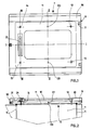
- an enclosure 1 such as an oven enclosure is limited by an upper wall 2, a lower wall 3, two side walls 4 and 5, a bottom not shown in the figures, and has an opening 6 opposite the bottom.
- a door 7 is provided to close the opening 6 of the enclosure 1.
- the door 7 comprises, in this embodiment, an outer wall 8 consisting of a rigid frame 80, for example metallic, articulated along a first vertical side 9 on the side wall 4 of the enclosure 1, in the vicinity of the edge of the opening 6.
- the rigid frame 80 borders a central wall 10 of which it is integral.
- the central wall 10 is a plate of transparent material such as glass.
- the door further comprises an inner plate 11, shaped to fit on the opening 6 of the enclosure 1 and close it in the closed position as shown in Figures 2 to 4.
- the plate interior 11 comprises guide rods, such as rods 12, 13, 14 and 15, fixed perpendicular to the plate in the vicinity of its edges.
- rods 12, 13, 14 and 15 fixed perpendicular to the plate in the vicinity of its edges.
- the rods are integral with the plate 11 at one of their ends, and are housed and slide in corresponding passages of the door frame 80, as shown in the figures.
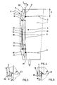
- Each rod is biased by a spring, such as the spring 16 associated with the rod 12, the spring 16 pushing the rod 12 away from the frame 80, the movement of the rod being limited by a stop not shown in the figures.
- the inner plate 11 is movable relative to the outer wall 8, by sliding the rods 12 to 15 and compressing the springs, as shown by the double arrows 17.
- the plate 11 has an outline whose dimensions are very close to the dimensions of the enclosure opening 6, and is arranged so that, in the closed position, the interior plate outline applies against the enclosure opening contour with the interposition of a seal 18.
- the seal borders the contour of the inner plate 11. It therefore includes an inner groove 180 into which the peripheral edge of the inner plate 11 is inserted.
- the inner plate 11 comes apply in abutment against the front face 21 of the enclosure 1 bordering the opening contour 6, and is held by the springs 16 compressed between said inner plate 11 and the door frame 80.
- the outer door wall 8 is itself provided with hooking means allowing its selective locking on the oven enclosure in the closed position.
- the attachment means can be of all types commonly used, and are therefore not shown in the drawings.
- FIG. 5 There is shown in Figures 5 and 6 the detail of embodiment of a seal 18 according to an advantageous embodiment.
- the seal has an external wing 19 and an internal wing 20, defining a section having the general shape of an L.
- the internal wing 20 comes to bear against the internal face 22 of the enclosure opening edge, while the outer wing 19 bears against the front face 21 of the enclosure opening edge.
- the seal is a deformable hollow profile, as shown in FIGS. 5 and 6, such that, when the outer wing 19 bears against the front face 21 of the enclosure opening edge, the seal deforms and its internal wing 20 moves radially to press against the internal face 22 of the enclosure opening.
- the internal seal wing 20 is offset towards the center of the door, facilitating the introduction of the seal inside the opening 6 of the enclosure when the door is closed.
- the fact that the internal wing 20 of seal 18 penetrates inside the opening 6 of the enclosure facilitates the channeling of condensed water towards the interior of the enclosure, avoiding the exit of water during the door opening.
- the inner plate 11 is advantageously made of a glass plate comprising a layer reflecting the infrared rays.
- the reflective layer is applied against the external face 23 of the plate 11. It is possible, for example, to use a plate of a material sold commercially under the brand name "Thermax" from the company Schott.
- a light source such as a luminescent tube 24 is disposed in the door, carried by the frame 80, outside the inner plate 11.
- the luminescent tube 24 is thus protected from the high temperature prevailing inside the enclosure 1, by the interposed inner plate 11.
- An additional transparent protective plate 28 is further adapted to close the door housing 29 in which the luminescent tube 24 is placed.
- a hollow zone 31 acting as a handle is provided on the outer face of the door frame 80, in the vertical upright 32 opposite the articulation.
- the outer wall 8 is of larger dimensions than the inner plate 11, and has a peripheral portion which projects beyond the contour of the inner plate 11, and which forms a protective return whose edge, such as the edge 320, is opposite the front face 21 of the enclosure.
- the space separating the edges 320 and the front face 21 defines passages 25 and 26 whose thickness E is advantageously between 0.5 and 3 centimeters.
- the edges of the outer wall 8 project beyond the contour of the inner plate 11 at a distance D greater than 5 centimeters.
- the inner face 32 of the outer wall 8 remains relatively spaced from the plane of the inner plate 11 over all or part of the distance D, to define an expansion volume V surrounding the periphery of the inner plate 11.
- the depth of the volume V is advantageously greater than 1 centimeter, its width being greater than 4 centimeters.
- springs such as spring 16 of suitable stiffness springs close to the preferred side must have a lower stiffness than springs close to the opposite side.
- L air circulates between the external atmosphere and the space 30 formed between the internal plate 11 and the internal face 32 of the external wall 8.
- the space 30 advantageously has a thickness of About 1 cm. This air circulation promotes the cooling of the central wall 10 of the door, and of the frame 80.
- the passages 25 and 26 can advantageously be provided respectively in the lower part and in the upper part of the junction between the frame 80 and the enclosure 1. , to take advantage of the chimney effect and promote air circulation between the exterior wall and the enclosure.
- the outer wall 8 advantageously has a shape in which the door 7 is curved, its inner face 32 facing the opening 6 of the enclosure being hollow.
- the inner plate 11 is housed in the hollow formed by the inner face 32 of the door 7, is bordered by the expansion volume V, and is thus protected around its edges by the frame 80.
- the edges of the frame 80 form a protective return of the inner plate 11. This provides mechanical protection of the inner plate 11, in particular preventing the inner plate 11 from being hooked and moved laterally in its plane, direction of movement in which the rods 12 to 15 have lower mechanical strength. And the user is prevented from touching the hot edges of the inner plate 11 when the oven is opened.
- the inner plate 11 is fixed on the rods 12 to 15 in a removable manner, so that the user can easily separate the plate 11 from the rods for cleaning its face 23, and for cleaning the inner face 32 of the outer wall 8.
- the inner plate 11 is fixed by only two rods 120 and 130 in the middle of two opposite sides perpendicular to the first side 9 of the wall outer 8, that is to say perpendicular to the hinge.
- This possibility of pivoting can be ensured by articulations such as the articulation 131 , of axis II-II, formed in the intermediate part of the rods 120 and 130.
- the outer wall returns 8 are spaced apart enough from the edges of the inner plate 11, to leave a sufficient volume V between the edges of the inner plate 11 and the inner wall 32 of the frame 80. In this case, by pivoting the inner plate 11, access to the space 30 between the inner plate 11 and the outer wall 8 is freed, allowing for example cleaning of the walls.
Landscapes
- Engineering & Computer Science (AREA)
- Chemical & Material Sciences (AREA)
- Combustion & Propulsion (AREA)
- Mechanical Engineering (AREA)
- General Engineering & Computer Science (AREA)
- Electric Ovens (AREA)
- Securing Of Glass Panes Or The Like (AREA)
Applications Claiming Priority (2)
| Application Number | Priority Date | Filing Date | Title |
|---|---|---|---|
| FR8815208A FR2639097A1 (fr) | 1988-11-17 | 1988-11-17 | Four a porte double |
| FR8815208 | 1988-11-17 |
Publications (2)
| Publication Number | Publication Date |
|---|---|
| EP0369905A1 true EP0369905A1 (de) | 1990-05-23 |
| EP0369905B1 EP0369905B1 (de) | 1992-07-29 |
Family
ID=9372116
Family Applications (1)
| Application Number | Title | Priority Date | Filing Date |
|---|---|---|---|
| EP89420442A Expired - Lifetime EP0369905B1 (de) | 1988-11-17 | 1989-11-15 | Backofen mit Doppeltür |
Country Status (5)
| Country | Link |
|---|---|
| US (1) | US5022380A (de) |
| EP (1) | EP0369905B1 (de) |
| DE (1) | DE68902298T2 (de) |
| ES (1) | ES2034730T3 (de) |
| FR (1) | FR2639097A1 (de) |
Cited By (4)
| Publication number | Priority date | Publication date | Assignee | Title |
|---|---|---|---|---|
| ITMI20110274A1 (it) * | 2011-02-23 | 2012-08-24 | Foster S P A | Forno per uso domestico con doppia porta |
| ES2395605A1 (es) * | 2010-11-17 | 2013-02-13 | BSH Electrodomésticos España S.A. | Dispositivo de aparato doméstico |
| ES2394693R1 (es) * | 2010-11-17 | 2013-02-25 | Bsh Electrodomesticos Espana | Dispositivo de aparato doméstico |
| EP2747515B1 (de) | 2012-12-20 | 2021-03-03 | Miele & Cie. KG | Gargerät |
Families Citing this family (23)
| Publication number | Priority date | Publication date | Assignee | Title |
|---|---|---|---|---|
| FR2705765B1 (fr) * | 1993-04-29 | 1995-08-18 | Eurofours Sa | Porte de four. |
| DE4315814C2 (de) * | 1993-05-12 | 2003-06-18 | Aeg Hausgeraete Gmbh | Beheiztes Haushaltsgerät, wie Herd oder Backofen |
| DE29503872U1 (de) | 1995-03-07 | 1996-07-04 | AEG Hausgeräte GmbH, 90429 Nürnberg | Tür zum Verschließen der Ofenmuffel eines Back- und Bratofens |
| US5782231A (en) * | 1997-02-24 | 1998-07-21 | Temco Fireplace Products, Inc. | Direct vent fireplace |
| US5960785A (en) * | 1997-05-28 | 1999-10-05 | American Trim, Llc | Cooking range oven having insulated oven door with viewing system |
| US5887916A (en) * | 1997-09-25 | 1999-03-30 | Kason Industries, Inc. | Safety door latch for pressurized ovens |
| FR2792713B1 (fr) | 1999-04-26 | 2001-07-20 | Simon | Four a porte froide |
| DE19933251A1 (de) * | 1999-07-15 | 2001-01-25 | Aeg Hausgeraete Gmbh | Tür für ein Gerät, insbesondere einen Garofen |
| DE10044376B4 (de) * | 2000-09-08 | 2008-05-29 | AEG Hausgeräte GmbH | Backgerät |
| KR100468121B1 (ko) | 2002-06-29 | 2005-01-26 | 삼성전자주식회사 | 전자렌지 |
| DE10318859A1 (de) * | 2003-04-25 | 2004-11-11 | BSH Bosch und Siemens Hausgeräte GmbH | Gargerät |
| DE10336138B3 (de) * | 2003-08-04 | 2004-10-14 | Miele & Cie. Kg | Tür für ein Haushaltsgerät mit demontierbarer Scheibe |
| US7478502B2 (en) * | 2003-08-14 | 2009-01-20 | Gemtron Corporation | Appliance doors |
| DE10341330A1 (de) * | 2003-09-08 | 2005-03-31 | BSH Bosch und Siemens Hausgeräte GmbH | Haushaltsgerät |
| DE102007058942A1 (de) * | 2007-12-07 | 2009-06-10 | BSH Bosch und Siemens Hausgeräte GmbH | Gargerät |
| ITBO20080557A1 (it) * | 2008-09-12 | 2010-03-13 | Premark Feg Llc | Forno industriale |
| NL2002409C2 (nl) * | 2009-01-09 | 2010-07-13 | D & J Holding B V | Beveiligde haard voor het stoken van gasvormige en/of vluchtige vloeibare brandstoffen. |
| US9016270B2 (en) * | 2011-01-05 | 2015-04-28 | General Electric Company | Window mounting for thermal expansion in an oven appliance |
| JP2013087962A (ja) * | 2011-10-13 | 2013-05-13 | Panasonic Corp | 加熱調理装置 |
| CN103836964B (zh) * | 2012-11-26 | 2016-11-23 | 江苏华东炉业有限公司 | 炉门密封结构 |
| DE102015100824A1 (de) * | 2015-01-21 | 2016-07-21 | Rational Ag | Tür sowie Gargerät |
| KR20170101466A (ko) * | 2016-02-29 | 2017-09-06 | 삼성전자주식회사 | 오븐 |
| DE102017220151A1 (de) * | 2017-11-13 | 2019-05-16 | BSH Hausgeräte GmbH | Haushaltsgargerät |
Citations (5)
| Publication number | Priority date | Publication date | Assignee | Title |
|---|---|---|---|---|
| GB740652A (en) * | 1953-08-08 | 1955-11-16 | Stoves Ltd | Improvements in or relating to doors for cabinets or containers such for example as domestic ovens and refrigerators |
| GB864816A (en) * | 1958-08-18 | 1961-04-06 | Gen Electric Co Ltd | Improvements in or relating to domestic cookers |
| DE1906621B1 (de) * | 1969-02-11 | 1970-09-03 | Licentia Gmbh | Bratraumtuere fuer Kuechenherde |
| FR2474654A1 (fr) * | 1980-01-29 | 1981-07-31 | Rhone Fonderies Atel | Dispositif d'eclairage pour four de cuisiniere a usage domestique |
| EP0183559A2 (de) * | 1984-11-28 | 1986-06-04 | Kent Heating Limited | Heizungsgerät |
Family Cites Families (4)
| Publication number | Priority date | Publication date | Assignee | Title |
|---|---|---|---|---|
| US3234899A (en) * | 1963-08-09 | 1966-02-15 | Weil Mclain Company Inc | Boiler construction |
| US4048978A (en) * | 1972-03-02 | 1977-09-20 | Glaverbel-Mecaniver | Heat insulating screen |
| FR2561359B1 (fr) * | 1984-01-17 | 1986-10-24 | Eurofours Sa | Dispositif de montage d'une vitre pour porte de four |
| DE8714544U1 (de) * | 1987-10-31 | 1987-12-23 | Degussa Ag, 6000 Frankfurt | Ofenverschluß für Industrieöfen |
-
1988
- 1988-11-17 FR FR8815208A patent/FR2639097A1/fr active Pending
-
1989
- 1989-11-15 ES ES198989420442T patent/ES2034730T3/es not_active Expired - Lifetime
- 1989-11-15 EP EP89420442A patent/EP0369905B1/de not_active Expired - Lifetime
- 1989-11-15 DE DE8989420442T patent/DE68902298T2/de not_active Expired - Fee Related
- 1989-11-17 US US07/438,577 patent/US5022380A/en not_active Expired - Lifetime
Patent Citations (5)
| Publication number | Priority date | Publication date | Assignee | Title |
|---|---|---|---|---|
| GB740652A (en) * | 1953-08-08 | 1955-11-16 | Stoves Ltd | Improvements in or relating to doors for cabinets or containers such for example as domestic ovens and refrigerators |
| GB864816A (en) * | 1958-08-18 | 1961-04-06 | Gen Electric Co Ltd | Improvements in or relating to domestic cookers |
| DE1906621B1 (de) * | 1969-02-11 | 1970-09-03 | Licentia Gmbh | Bratraumtuere fuer Kuechenherde |
| FR2474654A1 (fr) * | 1980-01-29 | 1981-07-31 | Rhone Fonderies Atel | Dispositif d'eclairage pour four de cuisiniere a usage domestique |
| EP0183559A2 (de) * | 1984-11-28 | 1986-06-04 | Kent Heating Limited | Heizungsgerät |
Cited By (5)
| Publication number | Priority date | Publication date | Assignee | Title |
|---|---|---|---|---|
| ES2395605A1 (es) * | 2010-11-17 | 2013-02-13 | BSH Electrodomésticos España S.A. | Dispositivo de aparato doméstico |
| ES2394693R1 (es) * | 2010-11-17 | 2013-02-25 | Bsh Electrodomesticos Espana | Dispositivo de aparato doméstico |
| ITMI20110274A1 (it) * | 2011-02-23 | 2012-08-24 | Foster S P A | Forno per uso domestico con doppia porta |
| EP2747515B1 (de) | 2012-12-20 | 2021-03-03 | Miele & Cie. KG | Gargerät |
| EP2747515B2 (de) † | 2012-12-20 | 2025-05-21 | Miele & Cie. KG | Gargerät |
Also Published As
| Publication number | Publication date |
|---|---|
| ES2034730T3 (es) | 1993-04-01 |
| FR2639097A1 (fr) | 1990-05-18 |
| US5022380A (en) | 1991-06-11 |
| DE68902298T2 (de) | 1993-02-18 |
| EP0369905B1 (de) | 1992-07-29 |
| DE68902298D1 (de) | 1992-09-03 |
Similar Documents
| Publication | Publication Date | Title |
|---|---|---|
| EP0369905B1 (de) | Backofen mit Doppeltür | |
| EP3028957B1 (de) | Umkehrbarer deckel und behälter, der eine lebensmitteldose mit variablem volumen bildet | |
| EP0229804B1 (de) | Nahrungsmittelbehälter mit vorrichtung zum aufwärmen durch exothermische reaktion zweier substanzen | |
| EP0540110A1 (de) | Flexible aufrollbare Tür mit verstärkter Wärmedämmung | |
| WO2008102073A1 (fr) | Appareil de cuisson sous pression muni d'un verrou | |
| EP0850850A1 (de) | Spender für Handschuhe aus Folienmaterial | |
| CA2621216A1 (fr) | Capot de nacelle pour turboreacteur et nacelle comportant au moins un tel capot | |
| EP2078918B1 (de) | Multipler Raketenbehälter und Vielzweckraketenabschussvorrichtung | |
| EP0972663B1 (de) | Abschlussvorrichtung für Öffnung in einer Fahrzeugkarosserie mit Griff mit geneigter Fläche | |
| EP0061400B1 (de) | Verfahren und Vorrichtung zum dichten Verschliessen und zum Öffnen eines Behälters für bestrahlten Kernbrennstoff | |
| EP3320778B1 (de) | Ofen, der abdichtungsmittel umfasst | |
| EP2515043B1 (de) | Feuerstelle umfassend eine Abdichtungsvorrichtung | |
| EP0539300A1 (de) | Türverschlussvorrichtung für einen isolierten Raum | |
| FR2835400A1 (fr) | Cendrier associable a un paquet de cigarettes | |
| FR2759770A1 (fr) | Four menager avec garniture d'etancheite pour l'ouverture frontale d'alimentation | |
| EP0255413B1 (de) | Tür für Haushaltskochherd | |
| EP1048902B1 (de) | Backofen mit gekühlter Tür | |
| WO2011083263A1 (fr) | Unité de traitement d'ébauches de corps creux, équipée d'une chambre formant piège à lumière | |
| WO1993025854A1 (fr) | Cuiseur-sterilisateur solaire | |
| FR2753677A1 (fr) | Obturateur pour une ouverture traversant une paroi ayant une faible rigidite et son utilisation | |
| FR2814719A1 (fr) | Couvercle pour emballage de produits notamment alimentaires | |
| FR2702194A1 (fr) | Dispositif de fermeture destiné à un tube à presser. | |
| FR3066442A1 (fr) | Dispositif d'encadrement de trou de caisse a etancheite amelioree | |
| FR2656280A1 (fr) | Dispositif d'obturation automatique par effet thermique de conditionnement pour preparations alimentaires a consommation differee. | |
| FR2672778A1 (fr) | Casque pourvu d'un equipement optoelectronique. |
Legal Events
| Date | Code | Title | Description |
|---|---|---|---|
| PUAI | Public reference made under article 153(3) epc to a published international application that has entered the european phase |
Free format text: ORIGINAL CODE: 0009012 |
|
| AK | Designated contracting states |
Kind code of ref document: A1 Designated state(s): DE ES FR GB IT NL SE |
|
| 17P | Request for examination filed |
Effective date: 19901013 |
|
| 17Q | First examination report despatched |
Effective date: 19910328 |
|
| GRAA | (expected) grant |
Free format text: ORIGINAL CODE: 0009210 |
|
| AK | Designated contracting states |
Kind code of ref document: B1 Designated state(s): DE ES FR GB IT NL SE |
|
| REF | Corresponds to: |
Ref document number: 68902298 Country of ref document: DE Date of ref document: 19920903 |
|
| GBT | Gb: translation of ep patent filed (gb section 77(6)(a)/1977) | ||
| ITF | It: translation for a ep patent filed | ||
| GBCC | Gb: corrected translation (of claims) filed (gb section 80(3)/1977) | ||
| REG | Reference to a national code |
Ref country code: ES Ref legal event code: FG2A Ref document number: 2034730 Country of ref document: ES Kind code of ref document: T3 |
|
| PLBE | No opposition filed within time limit |
Free format text: ORIGINAL CODE: 0009261 |
|
| STAA | Information on the status of an ep patent application or granted ep patent |
Free format text: STATUS: NO OPPOSITION FILED WITHIN TIME LIMIT |
|
| 26N | No opposition filed | ||
| REG | Reference to a national code |
Ref country code: FR Ref legal event code: CL |
|
| REG | Reference to a national code |
Ref country code: FR Ref legal event code: RL |
|
| EAL | Se: european patent in force in sweden |
Ref document number: 89420442.9 |
|
| PGFP | Annual fee paid to national office [announced via postgrant information from national office to epo] |
Ref country code: SE Payment date: 19951024 Year of fee payment: 7 |
|
| PG25 | Lapsed in a contracting state [announced via postgrant information from national office to epo] |
Ref country code: SE Effective date: 19961116 |
|
| EUG | Se: european patent has lapsed |
Ref document number: 89420442.9 |
|
| PGFP | Annual fee paid to national office [announced via postgrant information from national office to epo] |
Ref country code: ES Payment date: 19981105 Year of fee payment: 10 |
|
| PGFP | Annual fee paid to national office [announced via postgrant information from national office to epo] |
Ref country code: NL Payment date: 19981130 Year of fee payment: 10 |
|
| PG25 | Lapsed in a contracting state [announced via postgrant information from national office to epo] |
Ref country code: ES Free format text: LAPSE BECAUSE OF NON-PAYMENT OF DUE FEES Effective date: 19991116 |
|
| PG25 | Lapsed in a contracting state [announced via postgrant information from national office to epo] |
Ref country code: NL Free format text: LAPSE BECAUSE OF NON-PAYMENT OF DUE FEES Effective date: 20000601 |
|
| NLV4 | Nl: lapsed or anulled due to non-payment of the annual fee |
Effective date: 20000601 |
|
| REG | Reference to a national code |
Ref country code: GB Ref legal event code: IF02 |
|
| REG | Reference to a national code |
Ref country code: ES Ref legal event code: FD2A Effective date: 20001214 |
|
| PG25 | Lapsed in a contracting state [announced via postgrant information from national office to epo] |
Ref country code: IT Free format text: LAPSE BECAUSE OF NON-PAYMENT OF DUE FEES;WARNING: LAPSES OF ITALIAN PATENTS WITH EFFECTIVE DATE BEFORE 2007 MAY HAVE OCCURRED AT ANY TIME BEFORE 2007. THE CORRECT EFFECTIVE DATE MAY BE DIFFERENT FROM THE ONE RECORDED. Effective date: 20051115 |
|
| PGFP | Annual fee paid to national office [announced via postgrant information from national office to epo] |
Ref country code: GB Payment date: 20061108 Year of fee payment: 18 |
|
| PGFP | Annual fee paid to national office [announced via postgrant information from national office to epo] |
Ref country code: FR Payment date: 20061113 Year of fee payment: 18 |
|
| PGFP | Annual fee paid to national office [announced via postgrant information from national office to epo] |
Ref country code: DE Payment date: 20061123 Year of fee payment: 18 |
|
| GBPC | Gb: european patent ceased through non-payment of renewal fee |
Effective date: 20071115 |
|
| PG25 | Lapsed in a contracting state [announced via postgrant information from national office to epo] |
Ref country code: DE Free format text: LAPSE BECAUSE OF NON-PAYMENT OF DUE FEES Effective date: 20080603 |
|
| REG | Reference to a national code |
Ref country code: FR Ref legal event code: ST Effective date: 20080930 |
|
| PG25 | Lapsed in a contracting state [announced via postgrant information from national office to epo] |
Ref country code: GB Free format text: LAPSE BECAUSE OF NON-PAYMENT OF DUE FEES Effective date: 20071115 |
|
| PG25 | Lapsed in a contracting state [announced via postgrant information from national office to epo] |
Ref country code: FR Free format text: LAPSE BECAUSE OF NON-PAYMENT OF DUE FEES Effective date: 20071130 |