EP0369906B1 - Backofen mit Verschluss - Google Patents
Backofen mit Verschluss Download PDFInfo
- Publication number
- EP0369906B1 EP0369906B1 EP19890420443 EP89420443A EP0369906B1 EP 0369906 B1 EP0369906 B1 EP 0369906B1 EP 19890420443 EP19890420443 EP 19890420443 EP 89420443 A EP89420443 A EP 89420443A EP 0369906 B1 EP0369906 B1 EP 0369906B1
- Authority
- EP
- European Patent Office
- Prior art keywords
- hook
- door
- oven
- locked position
- pin
- Prior art date
- Legal status (The legal status is an assumption and is not a legal conclusion. Google has not performed a legal analysis and makes no representation as to the accuracy of the status listed.)
- Expired - Lifetime
Links
- 230000000717 retained effect Effects 0.000 claims description 13
- 239000007789 gas Substances 0.000 claims description 7
- 230000000694 effects Effects 0.000 claims description 2
- 238000006073 displacement reaction Methods 0.000 claims 2
- 210000000056 organ Anatomy 0.000 description 5
- 208000031968 Cadaver Diseases 0.000 description 1
- 230000006835 compression Effects 0.000 description 1
- 238000007906 compression Methods 0.000 description 1
- 238000010411 cooking Methods 0.000 description 1
- 230000002349 favourable effect Effects 0.000 description 1
- 230000005484 gravity Effects 0.000 description 1
- 238000003780 insertion Methods 0.000 description 1
- 230000037431 insertion Effects 0.000 description 1
- 238000000034 method Methods 0.000 description 1
- 230000002093 peripheral effect Effects 0.000 description 1
- 238000007789 sealing Methods 0.000 description 1
Images

Classifications
-
- F—MECHANICAL ENGINEERING; LIGHTING; HEATING; WEAPONS; BLASTING
- F24—HEATING; RANGES; VENTILATING
- F24C—DOMESTIC STOVES OR RANGES ; DETAILS OF DOMESTIC STOVES OR RANGES, OF GENERAL APPLICATION
- F24C15/00—Details
- F24C15/02—Doors specially adapted for stoves or ranges
- F24C15/022—Latches
-
- E—FIXED CONSTRUCTIONS
- E05—LOCKS; KEYS; WINDOW OR DOOR FITTINGS; SAFES
- E05C—BOLTS OR FASTENING DEVICES FOR WINGS, SPECIALLY FOR DOORS OR WINDOWS
- E05C5/00—Fastening devices with bolts moving otherwise than only rectilinearly and only pivotally or rotatively
-
- Y—GENERAL TAGGING OF NEW TECHNOLOGICAL DEVELOPMENTS; GENERAL TAGGING OF CROSS-SECTIONAL TECHNOLOGIES SPANNING OVER SEVERAL SECTIONS OF THE IPC; TECHNICAL SUBJECTS COVERED BY FORMER USPC CROSS-REFERENCE ART COLLECTIONS [XRACs] AND DIGESTS
- Y10—TECHNICAL SUBJECTS COVERED BY FORMER USPC
- Y10T—TECHNICAL SUBJECTS COVERED BY FORMER US CLASSIFICATION
- Y10T292/00—Closure fasteners
- Y10T292/08—Bolts
- Y10T292/0911—Hooked end
- Y10T292/0913—Sliding and swinging
- Y10T292/0914—Operating means
- Y10T292/0917—Lever
-
- Y—GENERAL TAGGING OF NEW TECHNOLOGICAL DEVELOPMENTS; GENERAL TAGGING OF CROSS-SECTIONAL TECHNOLOGIES SPANNING OVER SEVERAL SECTIONS OF THE IPC; TECHNICAL SUBJECTS COVERED BY FORMER USPC CROSS-REFERENCE ART COLLECTIONS [XRACs] AND DIGESTS
- Y10—TECHNICAL SUBJECTS COVERED BY FORMER USPC
- Y10T—TECHNICAL SUBJECTS COVERED BY FORMER US CLASSIFICATION
- Y10T292/00—Closure fasteners
- Y10T292/08—Bolts
- Y10T292/0911—Hooked end
- Y10T292/0945—Operating means
- Y10T292/0951—Rigid
- Y10T292/0956—Sliding catch
Definitions
- an oven provided with a closure comprises a double door, with an outer wall with a rigid frame articulated along one of its sides on the edge of the enclosure; the door further comprises an inner plate, shaped to adapt to the opening of the enclosure and to close it in the closed position; the inner plate is mounted on the outer door wall opposite its inner face, to which it is connected by connecting means allowing the relative movement of the inner plate relative to the outer wall parallel to the movement of the door around its joints; the connecting means comprise elastic means urging the inner plate away from the door.
- the hook in the hooking position produces braking of the door and slows down the application of the inner plate on the opening of the enclosure.
- Such a slowdown is favorable to allow the seal to be positioned correctly relative to the walls of the oven enclosure, thus ensuring improved sealing.
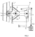
- the front part of the hook 7 comes out of the oven body 1 through a hole 18 formed in the wall of the oven body.
- the hook 7 comprises two protrusions 19 and 20, on either side of the hook 7, coming to bear against the front wall of the oven body 1 and thus closing the light 18 in the hooking position.
- the rear part of the flat hook body 8 7 includes an upper shoulder 22 intended to cooperate with a lower tooth 23 forming a movable stop and carried by a lever 24 rotating about a fixed axis 25 of the plate 4.
- the lever 24 is biased by an actuating rod 26 whose end comprises a core 27 of electromagnet 28 and a handle 29 for maneuvering.
- the electromagnet 28 is electrically connected in series on a power source 30 with a first switch 31 actuated by a door opening button 32 accessible by the user, and with a second switch 33 actuated by a ramp 34 of the hook 7.
- the second switch 33 is closed when the hook is in the locking position or back position, and is open when the hook is in all the other positions, and in particular in the hooking position shown in FIG. 1 .
Landscapes
- Engineering & Computer Science (AREA)
- Mechanical Engineering (AREA)
- Chemical & Material Sciences (AREA)
- Combustion & Propulsion (AREA)
- General Engineering & Computer Science (AREA)
- Electric Ovens (AREA)
Claims (10)
dadurch gekennzeichnet, daß
Applications Claiming Priority (2)
| Application Number | Priority Date | Filing Date | Title |
|---|---|---|---|
| FR8815209A FR2639096B1 (fr) | 1988-11-17 | 1988-11-17 | Fermeture pour four |
| FR8815209 | 1988-11-17 |
Publications (2)
| Publication Number | Publication Date |
|---|---|
| EP0369906A1 EP0369906A1 (de) | 1990-05-23 |
| EP0369906B1 true EP0369906B1 (de) | 1992-07-29 |
Family
ID=9372117
Family Applications (1)
| Application Number | Title | Priority Date | Filing Date |
|---|---|---|---|
| EP19890420443 Expired - Lifetime EP0369906B1 (de) | 1988-11-17 | 1989-11-15 | Backofen mit Verschluss |
Country Status (5)
| Country | Link |
|---|---|
| US (1) | US5012794A (de) |
| EP (1) | EP0369906B1 (de) |
| DE (1) | DE68902299T2 (de) |
| ES (1) | ES2034731T3 (de) |
| FR (1) | FR2639096B1 (de) |
Families Citing this family (33)
| Publication number | Priority date | Publication date | Assignee | Title |
|---|---|---|---|---|
| DE4040424A1 (de) * | 1990-12-18 | 1992-06-25 | Miele & Cie | Mikrowellenherd mit einer tuer |
| KR940007232B1 (ko) * | 1991-12-31 | 1994-08-10 | 대우전자 주식회사 | 전자렌지의 도어 개폐장치 |
| US5746456A (en) * | 1993-09-17 | 1998-05-05 | Societe Cooperative De Production Bourgeois | Oven door locking device |
| DE9401106U1 (de) * | 1994-01-24 | 1995-05-18 | Georg Fischer GmbH & Co Maschinen- u. Kesselfabrik, 89312 Günzburg | Türverriegelung für einen Heizkessel für feste Brennstoffe |
| DE19629361C1 (de) * | 1996-07-20 | 1997-11-20 | Heraeus Instr Gmbh | Schloß |
| DE10027774C2 (de) * | 2000-04-20 | 2003-08-21 | Miwe Michael Wenz Gmbh | Vorrichtung zum Schließen der Tür eines Ofens und Ofen |
| US6315336B1 (en) * | 2000-05-30 | 2001-11-13 | Summit Manufacturing, Inc. | Motorized self-cleaning oven latch |
| US6474702B1 (en) | 2000-08-16 | 2002-11-05 | France/Scott Fetzer Company | Range door lock with nuisance latch |
| US7441812B2 (en) * | 2000-08-27 | 2008-10-28 | Southco, Inc. | Linear compression latch |
| DE50009661D1 (de) * | 2000-12-22 | 2005-04-07 | Zangenstein Elektro | Vorrichtung zum Sperren und Freigeben eines Türschlosses eines elektrischen Gerätes |
| US7090263B2 (en) * | 2001-05-04 | 2006-08-15 | Spx Corporation | Door latching device and method |
| US6966582B1 (en) | 2001-11-02 | 2005-11-22 | France/Scott Fetzer Company | Lock rod clutch for oven latch |
| US7150480B2 (en) * | 2003-03-17 | 2006-12-19 | Maytag Corporation | Appliance lid lock and method for using same |
| DE102004002898A1 (de) * | 2004-01-20 | 2005-08-18 | Stolzlechner, Erwin, St. Johann | Automatische Schließeinrichtung für eine Ofentür |
| DE102004007122B4 (de) * | 2004-02-12 | 2006-11-16 | Miele & Cie. Kg | Verfahren zum Betreiben eines Gargeräts |
| US20050284460A1 (en) * | 2004-06-28 | 2005-12-29 | The Stanley Works | Oven door latch lock |
| DE102006001293B4 (de) * | 2006-01-10 | 2021-05-27 | BSH Hausgeräte GmbH | Gargerät und Verfahren zum Betreiben eines Gargeräts |
| US7334823B2 (en) * | 2006-05-05 | 2008-02-26 | Emerson Electric Co.. | Motorized oven lock having a reciprocating latch |
| DE102009019225B4 (de) * | 2008-04-30 | 2016-06-09 | Lg Electronics Inc. | Maschine zum Behandeln von Textil- und Lederwaren |
| US20100314889A1 (en) * | 2009-06-15 | 2010-12-16 | Solteam Electronics, Co., Ltd. | Latch assembly |
| US9944172B2 (en) * | 2010-03-31 | 2018-04-17 | Kiekert Ag | Actuator for a motor vehicle and locking device and method |
| GB2480434B (en) * | 2010-05-17 | 2014-12-03 | Rolls Royce Plc | Toggle clamp locking device |
| US9958166B2 (en) * | 2012-05-31 | 2018-05-01 | Bsh Home Appliances Corporation | Household appliance having a latch retainer for an all glass inner door |
| KR101299634B1 (ko) * | 2013-06-13 | 2013-08-23 | 주식회사 중앙금속 | 잠금장치 |
| ITTO20130691A1 (it) * | 2013-08-13 | 2015-02-14 | Elbi Int Spa | Apparecchiatura per controllare la chiusura di una porta di un elettrodomestico, in particolare per una macchina lavatrice, quale una macchina lavastoviglie. |
| US10315842B2 (en) * | 2014-06-20 | 2019-06-11 | Western Disposal, Inc. | System for securing a lid of a container to prevent animal intrusion |
| KR102459278B1 (ko) * | 2016-06-20 | 2022-10-26 | 엘지전자 주식회사 | 잠금장치 및 이를 포함하는 가전기기 |
| CN107559907B (zh) * | 2016-06-30 | 2020-01-17 | 博西华电器(江苏)有限公司 | 抽油烟机 |
| DE202016103884U1 (de) | 2016-07-18 | 2016-09-06 | Rational Aktiengesellschaft | Gargerät mit Verriegelungsvorrichtung |
| CN108731054A (zh) * | 2017-04-25 | 2018-11-02 | 嵊州市惠宁达厨房电器有限公司 | 一种便于拆卸的油烟机罩 |
| DE102017111166A1 (de) * | 2017-05-22 | 2018-11-22 | Rahrbach Gmbh | Elektromechanische Verschlusseinrichtung für Gerätetüren |
| CN111096663B (zh) * | 2020-01-17 | 2025-05-09 | 中山市华诺电器有限公司 | 一种弹压式水箱结构 |
| CN111288518B (zh) * | 2020-03-02 | 2022-01-25 | 宁波方太厨具有限公司 | 一种防脱挂钩组件及应用有该防脱挂钩组件的吸油烟机 |
Family Cites Families (5)
| Publication number | Priority date | Publication date | Assignee | Title |
|---|---|---|---|---|
| DE1906621B1 (de) * | 1969-02-11 | 1970-09-03 | Licentia Gmbh | Bratraumtuere fuer Kuechenherde |
| US3831580A (en) * | 1973-11-19 | 1974-08-27 | Corning Glass Works | Lockable oven door latch |
| US4163443A (en) * | 1977-08-15 | 1979-08-07 | Preway, Inc. | Latch mechanism for an oven door |
| US4351288A (en) * | 1981-06-17 | 1982-09-28 | White Consolidated Industries, Inc. | Oven door latch |
| US4554907A (en) * | 1983-12-12 | 1985-11-26 | Whirlpool Corporation | Latch for self-cleaning oven door |
-
1988
- 1988-11-17 FR FR8815209A patent/FR2639096B1/fr not_active Expired - Lifetime
-
1989
- 1989-11-15 ES ES89420443T patent/ES2034731T3/es not_active Expired - Lifetime
- 1989-11-15 DE DE8989420443T patent/DE68902299T2/de not_active Expired - Fee Related
- 1989-11-15 EP EP19890420443 patent/EP0369906B1/de not_active Expired - Lifetime
- 1989-11-17 US US07/438,625 patent/US5012794A/en not_active Expired - Lifetime
Also Published As
| Publication number | Publication date |
|---|---|
| EP0369906A1 (de) | 1990-05-23 |
| DE68902299D1 (de) | 1992-09-03 |
| US5012794A (en) | 1991-05-07 |
| DE68902299T2 (de) | 1993-02-04 |
| FR2639096B1 (fr) | 1991-01-04 |
| FR2639096A1 (fr) | 1990-05-18 |
| ES2034731T3 (es) | 1993-04-01 |
Similar Documents
| Publication | Publication Date | Title |
|---|---|---|
| EP0369906B1 (de) | Backofen mit Verschluss | |
| EP1081063B1 (de) | Vorrichtung zum automatisch durch Schwerkraft Verriegeln und Entriegeln des Deckels eines Behälters sowie Behälter mit einer derartigen Vorrichtung | |
| CA2688143C (fr) | Dispositif de verrouillage d'une partie ouvrante de nacelle de turboreacteur par rapport a une partie fixe, et nacelle equipee d'un tel dispositif | |
| FR2652120A1 (fr) | Mecanisme de verrouillage pour porte coulissante. | |
| FR2704489A1 (fr) | Dispositif de réglage pour un toit coulissant. | |
| EP0911469B1 (de) | Drehbare Tür mit einem Flügel, an dem zwei parallele Treibstangen mittels zweiarmiger Hebel montiert sind | |
| CH633070A5 (fr) | Dispositif de porte pour la securite de personnes. | |
| FR2477991A1 (fr) | Dispositif de fixation d'une ferrure reglable dans differentes positions, en particulier d'une ferrure pour sieges de vehicule | |
| FR2734597A1 (fr) | Dispositif de degagement de verrou de maintien de porte ouverte et procede | |
| FR2829439A1 (fr) | Pietement de siege de vehicule, siege comportant un tel pietement et ensemble d'assise comportant un tel siege | |
| FR2741857A1 (fr) | Element de butee d'arret | |
| CA1290208C (fr) | Porte guillotine perfectionnee pour foyer ferme de cheminee | |
| EP0002396B1 (de) | Lasthaken | |
| EP0737782A1 (de) | Beidseitige bedienbare Verriegelungsvorrichtung für eine Schachtabdeckung | |
| FR2641952A1 (fr) | Dispositif de fermeture au moyen d'un levier basculant et coulissant, notamment pour valises | |
| FR2910519A1 (fr) | Dispositif d'obturation d'une baie menagee dans la carrosserie d'un vehicule a pion mobile formant pene, et vehicule correspondant. | |
| FR2738864A1 (fr) | Serrure a combinaison et bagage equipe de cette serrure | |
| FR2732062A1 (fr) | Serrure de porte assurant une fonction d'etancheite et une fonction de securite | |
| FR2976959A1 (fr) | Verrou de trappe | |
| FR2736996A1 (fr) | Dispositif d'ouverture et de fermeture d'une porte d'acces a une enceinte, et four de cuisson equipe de ce dispositif | |
| FR2846358A1 (fr) | Dispositif de verrouillage pour baie a deux vantaux ouvrant a la francaise, et baie ainsi equipee | |
| FR2620160A1 (fr) | Verrou de securite | |
| FR2690478A1 (fr) | Foyer de cheminée à porte pivotante et escamotable. | |
| FR2650490A1 (de) | ||
| FR2601062A1 (fr) | Loquet de verrouillage a pene pivotant, destine notamment a une partie comportant une fermeture antipanique. |
Legal Events
| Date | Code | Title | Description |
|---|---|---|---|
| PUAI | Public reference made under article 153(3) epc to a published international application that has entered the european phase |
Free format text: ORIGINAL CODE: 0009012 |
|
| AK | Designated contracting states |
Kind code of ref document: A1 Designated state(s): DE ES GB IT NL SE |
|
| 17P | Request for examination filed |
Effective date: 19901013 |
|
| 17Q | First examination report despatched |
Effective date: 19910328 |
|
| GRAA | (expected) grant |
Free format text: ORIGINAL CODE: 0009210 |
|
| AK | Designated contracting states |
Kind code of ref document: B1 Designated state(s): DE ES GB IT NL SE |
|
| REF | Corresponds to: |
Ref document number: 68902299 Country of ref document: DE Date of ref document: 19920903 |
|
| GBT | Gb: translation of ep patent filed (gb section 77(6)(a)/1977) | ||
| ITF | It: translation for a ep patent filed | ||
| REG | Reference to a national code |
Ref country code: ES Ref legal event code: FG2A Ref document number: 2034731 Country of ref document: ES Kind code of ref document: T3 |
|
| PLBE | No opposition filed within time limit |
Free format text: ORIGINAL CODE: 0009261 |
|
| STAA | Information on the status of an ep patent application or granted ep patent |
Free format text: STATUS: NO OPPOSITION FILED WITHIN TIME LIMIT |
|
| 26N | No opposition filed | ||
| EAL | Se: european patent in force in sweden |
Ref document number: 89420443.7 |
|
| PGFP | Annual fee paid to national office [announced via postgrant information from national office to epo] |
Ref country code: SE Payment date: 19951024 Year of fee payment: 7 |
|
| PGFP | Annual fee paid to national office [announced via postgrant information from national office to epo] |
Ref country code: GB Payment date: 19961107 Year of fee payment: 8 |
|
| PGFP | Annual fee paid to national office [announced via postgrant information from national office to epo] |
Ref country code: ES Payment date: 19961111 Year of fee payment: 8 |
|
| PG25 | Lapsed in a contracting state [announced via postgrant information from national office to epo] |
Ref country code: SE Effective date: 19961116 |
|
| PGFP | Annual fee paid to national office [announced via postgrant information from national office to epo] |
Ref country code: NL Payment date: 19961130 Year of fee payment: 8 |
|
| PGFP | Annual fee paid to national office [announced via postgrant information from national office to epo] |
Ref country code: DE Payment date: 19961227 Year of fee payment: 8 |
|
| EUG | Se: european patent has lapsed |
Ref document number: 89420443.7 |
|
| PG25 | Lapsed in a contracting state [announced via postgrant information from national office to epo] |
Ref country code: GB Free format text: LAPSE BECAUSE OF NON-PAYMENT OF DUE FEES Effective date: 19971115 |
|
| PG25 | Lapsed in a contracting state [announced via postgrant information from national office to epo] |
Ref country code: ES Free format text: LAPSE BECAUSE OF NON-PAYMENT OF DUE FEES Effective date: 19971116 |
|
| PG25 | Lapsed in a contracting state [announced via postgrant information from national office to epo] |
Ref country code: NL Free format text: LAPSE BECAUSE OF NON-PAYMENT OF DUE FEES Effective date: 19980601 |
|
| GBPC | Gb: european patent ceased through non-payment of renewal fee |
Effective date: 19971115 |
|
| PG25 | Lapsed in a contracting state [announced via postgrant information from national office to epo] |
Ref country code: DE Free format text: LAPSE BECAUSE OF NON-PAYMENT OF DUE FEES Effective date: 19980801 |
|
| NLV4 | Nl: lapsed or anulled due to non-payment of the annual fee |
Effective date: 19980601 |
|
| REG | Reference to a national code |
Ref country code: ES Ref legal event code: FD2A Effective date: 19981212 |
|
| PG25 | Lapsed in a contracting state [announced via postgrant information from national office to epo] |
Ref country code: IT Free format text: LAPSE BECAUSE OF NON-PAYMENT OF DUE FEES;WARNING: LAPSES OF ITALIAN PATENTS WITH EFFECTIVE DATE BEFORE 2007 MAY HAVE OCCURRED AT ANY TIME BEFORE 2007. THE CORRECT EFFECTIVE DATE MAY BE DIFFERENT FROM THE ONE RECORDED. Effective date: 20051115 |