EP0369918A1 - Verfahren und Vorrichtung zum Wahrnehmen des Standes eines Ventils - Google Patents
Verfahren und Vorrichtung zum Wahrnehmen des Standes eines Ventils Download PDFInfo
- Publication number
- EP0369918A1 EP0369918A1 EP89470020A EP89470020A EP0369918A1 EP 0369918 A1 EP0369918 A1 EP 0369918A1 EP 89470020 A EP89470020 A EP 89470020A EP 89470020 A EP89470020 A EP 89470020A EP 0369918 A1 EP0369918 A1 EP 0369918A1
- Authority
- EP
- European Patent Office
- Prior art keywords
- coil
- valve
- circuit
- core
- state
- Prior art date
- Legal status (The legal status is an assumption and is not a legal conclusion. Google has not performed a legal analysis and makes no representation as to the accuracy of the status listed.)
- Granted
Links
- 238000000034 method Methods 0.000 title claims abstract description 10
- 230000004907 flux Effects 0.000 claims abstract description 12
- 238000001514 detection method Methods 0.000 claims abstract description 8
- 230000001419 dependent effect Effects 0.000 claims abstract description 5
- 230000010355 oscillation Effects 0.000 claims abstract description 5
- 238000006073 displacement reaction Methods 0.000 claims abstract description 4
- 230000005284 excitation Effects 0.000 claims description 20
- 238000005259 measurement Methods 0.000 claims description 17
- 229910000859 α-Fe Inorganic materials 0.000 claims description 5
- 230000011664 signaling Effects 0.000 claims description 4
- 230000008878 coupling Effects 0.000 claims description 3
- 238000010168 coupling process Methods 0.000 claims description 3
- 238000005859 coupling reaction Methods 0.000 claims description 3
- 239000003990 capacitor Substances 0.000 description 3
- 239000011347 resin Substances 0.000 description 3
- 229920005989 resin Polymers 0.000 description 3
- 230000000295 complement effect Effects 0.000 description 2
- 239000000428 dust Substances 0.000 description 2
- 238000009434 installation Methods 0.000 description 2
- XLYOFNOQVPJJNP-UHFFFAOYSA-N water Substances O XLYOFNOQVPJJNP-UHFFFAOYSA-N 0.000 description 2
- 229910001018 Cast iron Inorganic materials 0.000 description 1
- 240000008042 Zea mays Species 0.000 description 1
- 238000010276 construction Methods 0.000 description 1
- 238000010586 diagram Methods 0.000 description 1
- 238000007599 discharging Methods 0.000 description 1
- 230000005288 electromagnetic effect Effects 0.000 description 1
- 238000002474 experimental method Methods 0.000 description 1
- 238000003780 insertion Methods 0.000 description 1
- 230000037431 insertion Effects 0.000 description 1
- 238000012423 maintenance Methods 0.000 description 1
- 230000014759 maintenance of location Effects 0.000 description 1
- 239000000463 material Substances 0.000 description 1
- 230000000007 visual effect Effects 0.000 description 1
- 239000002351 wastewater Substances 0.000 description 1
Images

Classifications
-
- G—PHYSICS
- G01—MEASURING; TESTING
- G01D—MEASURING NOT SPECIALLY ADAPTED FOR A SPECIFIC VARIABLE; ARRANGEMENTS FOR MEASURING TWO OR MORE VARIABLES NOT COVERED IN A SINGLE OTHER SUBCLASS; TARIFF METERING APPARATUS; MEASURING OR TESTING NOT OTHERWISE PROVIDED FOR
- G01D5/00—Mechanical means for transferring the output of a sensing member; Means for converting the output of a sensing member to another variable where the form or nature of the sensing member does not constrain the means for converting; Transducers not specially adapted for a specific variable
- G01D5/12—Mechanical means for transferring the output of a sensing member; Means for converting the output of a sensing member to another variable where the form or nature of the sensing member does not constrain the means for converting; Transducers not specially adapted for a specific variable using electric or magnetic means
- G01D5/14—Mechanical means for transferring the output of a sensing member; Means for converting the output of a sensing member to another variable where the form or nature of the sensing member does not constrain the means for converting; Transducers not specially adapted for a specific variable using electric or magnetic means influencing the magnitude of a current or voltage
- G01D5/20—Mechanical means for transferring the output of a sensing member; Means for converting the output of a sensing member to another variable where the form or nature of the sensing member does not constrain the means for converting; Transducers not specially adapted for a specific variable using electric or magnetic means influencing the magnitude of a current or voltage by varying inductance, e.g. by a movable armature
- G01D5/204—Mechanical means for transferring the output of a sensing member; Means for converting the output of a sensing member to another variable where the form or nature of the sensing member does not constrain the means for converting; Transducers not specially adapted for a specific variable using electric or magnetic means influencing the magnitude of a current or voltage by varying inductance, e.g. by a movable armature by influencing the mutual induction between two or more coils
- G01D5/2046—Mechanical means for transferring the output of a sensing member; Means for converting the output of a sensing member to another variable where the form or nature of the sensing member does not constrain the means for converting; Transducers not specially adapted for a specific variable using electric or magnetic means influencing the magnitude of a current or voltage by varying inductance, e.g. by a movable armature by influencing the mutual induction between two or more coils by a movable ferromagnetic element, e.g. a core
-
- F—MECHANICAL ENGINEERING; LIGHTING; HEATING; WEAPONS; BLASTING
- F16—ENGINEERING ELEMENTS AND UNITS; GENERAL MEASURES FOR PRODUCING AND MAINTAINING EFFECTIVE FUNCTIONING OF MACHINES OR INSTALLATIONS; THERMAL INSULATION IN GENERAL
- F16K—VALVES; TAPS; COCKS; ACTUATING-FLOATS; DEVICES FOR VENTING OR AERATING
- F16K37/00—Special means in or on valves or other cut-off apparatus for indicating or recording operation thereof, or for enabling an alarm to be given
- F16K37/0025—Electrical or magnetic means
- F16K37/0041—Electrical or magnetic means for measuring valve parameters
Definitions
- the present invention relates to a method and a device making it possible to detect the state, for example open state or closed state or possibly an intermediate state, of a valve which incorporates, for this purpose, an electric coil with a moving core linearly displaceable in correspondence with the displacement of the valve shutter member.
- the invention relates more particularly, although not exclusively, to the control of the state of valves which are located out of sight and / or touch of an operator, for example at the bottom of a deep and poorly lit gaze which prevents a visual check, even manual probing, correct.
- the second coil is used which is included in an electrical circuit comprising a source of continuous electrical power and the variation of magnetic flux is generated by the opening of said circuit.
- the use of electrical components with an electromagnetic effect makes it possible to be able to carry out the detection from the outside of the valve, without it being necessary to have access to the inside. of it.
- the use of components which are inherently inert avoids the presence in the valve of a source of electrical energy and gives the installation arranged in the valve the desirable functional autonomy with a view to high availability of the installation.
- the mobile unit plays all 'first a role of transmitter by generating an energy pulse which is transmitted to the unit fixed in the valve which then plays the role of receiver of this energy pulse; then by an inversion of the roles, the unit fixed in the valve restores this energetic pulse modified according to the variable parameter of the oscillating circuit (that is to say the position of the core within the coil) while playing the role transmitter, this modified pulse being detected by the mobile unit which then plays in turn the role of receiver.
- the oscillating circuit unit fixed in the valve acts as a deforming electric mirror, the analysis of the deformation providing the information sought.
- the excitation means comprise an electrical excitation circuit constituted by, in series, an excitation coil, a source of continuous electrical energy and a switch; in this case, preferably the excitation coil and the measurement coil are one and the same coil (second coil) successively included in the excitation circuit, then in the measurement circuit, which leads to a simpler, less expensive and less bulky circuit; always in this case, and for the same reasons, it is desirable that the switch of the excitation circuit is arranged in the form of a switch connecting one of the terminals of the second coil selectively to the excitation circuit or to the measurement circuit .
- the fixed unit and the mobile unit respectively have mutually cooperating surfaces forming positioning spans such that, when the mobile unit is approached to the fixed unit, the two respective coils are positioned mutually substantially coaxially and at a predetermined distance from each other.
- the mutually cooperating bearing surfaces form respectively male and female coupling volumes.
- the valve has a projecting part constituting the aforementioned male volume and housing at least the first coil, and the second coil is housed behind the bottom surface of a recess constituting the aforementioned female volume and provided in a positioning cap, said recess having a configuration such that it allows positioning on the valve operating rod without allowing its operation.
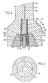
- the projecting part is substantially in the form of a truncated pyramid of square cross section and constitutes the operating head of the valve shutter member
- the positioning cap is in the form of a truncated cone.
- a positioning cap having a recess which has a configuration complementary to that of the projecting part of the valve, thus allowing, if it is in a sufficiently resistant material, to operate the valve after reading without changing the tool.
- the mobile unit is constituted in the form of a rod incorporating all the components and one free end of which carries the aforementioned positioning cap.
- Figure 1 is shown the electrical diagram of the means used in accordance with the invention to remotely detect the state of this valve.
- a fixed unit 5 constituted by an electric coil 6 at the terminals of which a capacitor 7 is connected in parallel.
- the coil 6 is provided with a core 8 which is linearly movable along its axis and which is mechanically coupled (dashed line 9) to the shutter member of the valve or to the actuating means thereof so that the movement of the shutter member or its drive means causes a displacement linear (double arrow 10) proportional to the core 8.
- the coil 6 and the capacitor 7 constitute a parallel oscillating electrical circuit whose resonant frequency varies with the depression of the core 8, in other words varies with the position of the shutter member of valve.
- a mobile unit 11 is also provided which is physically independent of the fixed unit 5.
- the mobile unit 11 also includes a coil 12, the terminals of which are connected, via a switch member 13, to the terminals d a source of continuous electrical energy 14 (cell or battery).
- a resistor 28 is interposed between the energy source 14 and the coil 12, this to prevent the mobile unit 11 from forming an oscillating circuit.
- the operation of the device is as follows.
- the mobile unit 11 is brought close to the fixed unit 5 (a way of proceeding will be indicated below) so that the two coils 6 and 12 are substantially coaxial.
- the switch member 13, initially in the closed position, is open.
- the rupture of the electrical circuit in which the coil 12 is included generates a variation in its magnetic flux.
- This variation, picked up by the coil 6, causes therein the appearance of a damped sinusoidal current which circulates in the oscillating circuit.
- the coil 6 Due to the circulation of this current, the coil 6 in turn generates a magnetic flux which induces in the coil 12 an alternating voltage whose frequency is a function of the insertion of the core 8 into the coil 6, and therefore a function of the position of the valve shutter member.
- This cast iron head is pierced axially at 17 (fig. 3) and houses the coil 6 arranged coaxially in the vertical direction, being embedded in an electrically insulating resin filling 18.
- This filling is itself tubular so as to release a free central channel 19 in which the core 8 made of ferrite can slide axially, freely.
- the operating head 2 is capable, during a measurement process, of being capped by a positioning cap 21 (belonging to a measuring device which will be described more fully below) provided at its lower part with a recess 22 in the form of a truncated cone or pyramid trunk complementary to the operating head 3.
- a positioning cap 21 (belonging to a measuring device which will be described more fully below) provided at its lower part with a recess 22 in the form of a truncated cone or pyramid trunk complementary to the operating head 3.
- a positioning cap 21 (belonging to a measuring device which will be described more fully below) provided at its lower part with a recess 22 in the form of a truncated cone or pyramid trunk complementary to the operating head 3.
- the coil 12 has a length of 17 mm, a diameter of 10 mm and consists of approximately 100 turns of an insulated wire of 0.3 mm in diameter; the coil 6 has a length of 10 mm, a diameter of 10 mm and is made up of approximately 100 turns of the same wire; capacitor 7 has a value of 1.5 ⁇ F; the source of electrical energy provides a direct voltage of 4.5 volts.
- the transmitting unit is permanently linked to the valve operating head; - the transmitting unit is inert; - the measurement is carried out without electrical or mechanical contact; - the measurement is made by proximity.
- the presence of dust and flows of all kinds between the transmitting unit and the receiving unit does not influence the measurement; it can be made for a distance between the two units from 0 to 15 mm.
Landscapes
- Engineering & Computer Science (AREA)
- General Engineering & Computer Science (AREA)
- Mechanical Engineering (AREA)
- Physics & Mathematics (AREA)
- General Physics & Mathematics (AREA)
- Indication Of The Valve Opening Or Closing Status (AREA)
- Measurement Of Length, Angles, Or The Like Using Electric Or Magnetic Means (AREA)
- Magnetically Actuated Valves (AREA)
Applications Claiming Priority (2)
| Application Number | Priority Date | Filing Date | Title |
|---|---|---|---|
| FR8814772A FR2639107B1 (fr) | 1988-11-14 | 1988-11-14 | Procede et dispositif pour detecter l'etat d'une vanne |
| FR8814772 | 1988-11-14 |
Publications (2)
| Publication Number | Publication Date |
|---|---|
| EP0369918A1 true EP0369918A1 (de) | 1990-05-23 |
| EP0369918B1 EP0369918B1 (de) | 1994-01-12 |
Family
ID=9371820
Family Applications (1)
| Application Number | Title | Priority Date | Filing Date |
|---|---|---|---|
| EP19890470020 Expired - Lifetime EP0369918B1 (de) | 1988-11-14 | 1989-11-03 | Verfahren und Vorrichtung zum Wahrnehmen des Standes eines Ventils |
Country Status (6)
| Country | Link |
|---|---|
| EP (1) | EP0369918B1 (de) |
| BR (1) | BR8905783A (de) |
| DE (1) | DE68912281T2 (de) |
| ES (1) | ES2041630T3 (de) |
| FR (1) | FR2639107B1 (de) |
| PT (1) | PT92268B (de) |
Cited By (3)
| Publication number | Priority date | Publication date | Assignee | Title |
|---|---|---|---|---|
| EP0651192A1 (de) * | 1993-10-29 | 1995-05-03 | Petroleo Brasileiro S.A. - Petrobras | Vorrichtung zur Anzeige des Betriebszustandes eines geradlinig bewegten Ventils |
| WO1996013639A1 (en) * | 1994-10-28 | 1996-05-09 | Technolog Limited | Valves |
| CN112378648A (zh) * | 2020-11-25 | 2021-02-19 | 重庆前卫表业有限公司 | 一种二线阀运行状态检测装置及方法 |
Families Citing this family (2)
| Publication number | Priority date | Publication date | Assignee | Title |
|---|---|---|---|---|
| DE202008005238U1 (de) | 2008-04-16 | 2008-07-31 | Vat Holding Ag | Vakuumventil-System mit Lageerkennung |
| FR3125333B1 (fr) * | 2021-07-16 | 2023-06-09 | Safran Electronics & Defense | Procédé et dispositif de prédiction de dysfonctionnements d’une électrovanne à double circuit |
Citations (4)
| Publication number | Priority date | Publication date | Assignee | Title |
|---|---|---|---|---|
| DE1116006B (de) * | 1959-11-12 | 1961-10-26 | Babcock & Wilcox Dampfkesselwe | Vorrichtung zur Stellungsanzeige bei gekapselten bzw. schwer zugaenglichen Absperreinrichtungen |
| FR2505443A1 (fr) * | 1981-05-08 | 1982-11-12 | Europ Agence Spatiale | Indicateur de position pour vanne, notamment pour vanne de verrouillage |
| DE3333144A1 (de) * | 1983-09-14 | 1985-03-28 | Alex 7956 Rot Gleinser | Vorrichtung zum verbinden einer unterflurarmatur, insbesondere einer anbohrarmatur, mit einer hochliegenden betaetigungsstelle |
| EP0252184A1 (de) * | 1986-06-05 | 1988-01-13 | M & FC HOLDING COMPANY, INC. | Zählerablesung durch einen Grubendeckel |
-
1988
- 1988-11-14 FR FR8814772A patent/FR2639107B1/fr not_active Expired - Lifetime
-
1989
- 1989-11-03 DE DE1989612281 patent/DE68912281T2/de not_active Expired - Fee Related
- 1989-11-03 EP EP19890470020 patent/EP0369918B1/de not_active Expired - Lifetime
- 1989-11-03 ES ES89470020T patent/ES2041630T3/es not_active Expired - Lifetime
- 1989-11-09 PT PT9226889A patent/PT92268B/pt not_active IP Right Cessation
- 1989-11-14 BR BR8905783A patent/BR8905783A/pt not_active IP Right Cessation
Patent Citations (4)
| Publication number | Priority date | Publication date | Assignee | Title |
|---|---|---|---|---|
| DE1116006B (de) * | 1959-11-12 | 1961-10-26 | Babcock & Wilcox Dampfkesselwe | Vorrichtung zur Stellungsanzeige bei gekapselten bzw. schwer zugaenglichen Absperreinrichtungen |
| FR2505443A1 (fr) * | 1981-05-08 | 1982-11-12 | Europ Agence Spatiale | Indicateur de position pour vanne, notamment pour vanne de verrouillage |
| DE3333144A1 (de) * | 1983-09-14 | 1985-03-28 | Alex 7956 Rot Gleinser | Vorrichtung zum verbinden einer unterflurarmatur, insbesondere einer anbohrarmatur, mit einer hochliegenden betaetigungsstelle |
| EP0252184A1 (de) * | 1986-06-05 | 1988-01-13 | M & FC HOLDING COMPANY, INC. | Zählerablesung durch einen Grubendeckel |
Cited By (3)
| Publication number | Priority date | Publication date | Assignee | Title |
|---|---|---|---|---|
| EP0651192A1 (de) * | 1993-10-29 | 1995-05-03 | Petroleo Brasileiro S.A. - Petrobras | Vorrichtung zur Anzeige des Betriebszustandes eines geradlinig bewegten Ventils |
| WO1996013639A1 (en) * | 1994-10-28 | 1996-05-09 | Technolog Limited | Valves |
| CN112378648A (zh) * | 2020-11-25 | 2021-02-19 | 重庆前卫表业有限公司 | 一种二线阀运行状态检测装置及方法 |
Also Published As
| Publication number | Publication date |
|---|---|
| BR8905783A (pt) | 1990-06-12 |
| ES2041630T1 (es) | 1993-12-01 |
| ES2041630T3 (es) | 1994-03-16 |
| EP0369918B1 (de) | 1994-01-12 |
| DE68912281D1 (de) | 1994-02-24 |
| DE68912281T2 (de) | 1994-05-11 |
| PT92268B (pt) | 1995-08-09 |
| FR2639107A1 (fr) | 1990-05-18 |
| FR2639107B1 (fr) | 1992-12-18 |
| PT92268A (pt) | 1990-05-31 |
Similar Documents
| Publication | Publication Date | Title |
|---|---|---|
| FR2780197A1 (fr) | Dispositif de disjonction automatique pour les situations d'urgence | |
| EP0121497B1 (de) | Linearbetätiger mit einem elektrischen Motor | |
| EP0365458A1 (de) | Magnetische Schlüssel und Schlösser für Zutrittskontrolle | |
| FR2709620A1 (fr) | Générateur d'impulsions à l'état solide. | |
| EP2575155B1 (de) | Gerät zur verteilung von strom mittlerer spannung | |
| EP0369918B1 (de) | Verfahren und Vorrichtung zum Wahrnehmen des Standes eines Ventils | |
| EP0949511A1 (de) | Vorrichtung zur Detektion der Öffnung eines Verbrauchszählers | |
| CH407345A (fr) | Appareil pour vérifier les caractéristiques ou la position d'un faisceau de particules chargées | |
| FR2953661A1 (fr) | Dispositif generateur d'energie electrique | |
| WO2014202849A1 (fr) | Ensemble de prises électriques | |
| BE1009000A3 (fr) | Commutateur par inductance sans contact sur levier de commande. | |
| FR2676589A1 (fr) | Commutateur electromagnetique. | |
| EP2200055B1 (de) | Elektrischer Schalter mit optimiertem Betrieb | |
| WO2019175000A1 (fr) | Actionneur de vanne, vanne et machine correspondantes | |
| EP2545573A1 (de) | Hybridschutzschalter mit schalter mit rückkehr nach der schliessung | |
| FR3092494A1 (fr) | Système de nettoyage et/ou de désinfection d’un tube creux, notamment une béquille de poignée de porte | |
| EP0419309B1 (de) | Vorrichtung zur Entnahme einer Fluidprobe aus einem Bohrloch | |
| FR2492605A1 (fr) | Moteur electrique transformant les impulsions d'attraction magnetique du rotor par le stator en un mouvement de rotation du rotor | |
| FR2564897A1 (fr) | Dispositif capteur de particules metalliques d'usure a l'interieur du carter d'un moteur ou appareil mecanique. | |
| FR2953059A1 (fr) | Dispositif de commande a distance | |
| FR2541776A1 (fr) | Accelerometres | |
| FR2658910A1 (fr) | Dispositif de mesure du niveau de carburant dans un reservoir de vehicule automobile. | |
| FR2588692A1 (fr) | Structure d'actionneur electromagnetique polarise | |
| FR2570184A1 (fr) | Indicateur magnetique de niveau | |
| FR2625313A1 (fr) | Jaugeur de niveau de reservoir a palpeur asservi |
Legal Events
| Date | Code | Title | Description |
|---|---|---|---|
| PUAI | Public reference made under article 153(3) epc to a published international application that has entered the european phase |
Free format text: ORIGINAL CODE: 0009012 |
|
| AK | Designated contracting states |
Kind code of ref document: A1 Designated state(s): BE DE ES FR GB IT LU NL |
|
| 17P | Request for examination filed |
Effective date: 19901015 |
|
| 17Q | First examination report despatched |
Effective date: 19920810 |
|
| GRAA | (expected) grant |
Free format text: ORIGINAL CODE: 0009210 |
|
| AK | Designated contracting states |
Kind code of ref document: B1 Designated state(s): BE DE ES FR GB IT LU NL |
|
| ITF | It: translation for a ep patent filed | ||
| GBT | Gb: translation of ep patent filed (gb section 77(6)(a)/1977) |
Effective date: 19940119 |
|
| REF | Corresponds to: |
Ref document number: 68912281 Country of ref document: DE Date of ref document: 19940224 |
|
| REG | Reference to a national code |
Ref country code: ES Ref legal event code: FG2A Ref document number: 2041630 Country of ref document: ES Kind code of ref document: T3 |
|
| PLBE | No opposition filed within time limit |
Free format text: ORIGINAL CODE: 0009261 |
|
| STAA | Information on the status of an ep patent application or granted ep patent |
Free format text: STATUS: NO OPPOSITION FILED WITHIN TIME LIMIT |
|
| 26N | No opposition filed | ||
| PGFP | Annual fee paid to national office [announced via postgrant information from national office to epo] |
Ref country code: NL Payment date: 19951017 Year of fee payment: 7 |
|
| PGFP | Annual fee paid to national office [announced via postgrant information from national office to epo] |
Ref country code: LU Payment date: 19951101 Year of fee payment: 7 |
|
| PGFP | Annual fee paid to national office [announced via postgrant information from national office to epo] |
Ref country code: ES Payment date: 19951116 Year of fee payment: 7 |
|
| PGFP | Annual fee paid to national office [announced via postgrant information from national office to epo] |
Ref country code: DE Payment date: 19951123 Year of fee payment: 7 |
|
| PGFP | Annual fee paid to national office [announced via postgrant information from national office to epo] |
Ref country code: BE Payment date: 19951208 Year of fee payment: 7 |
|
| PGFP | Annual fee paid to national office [announced via postgrant information from national office to epo] |
Ref country code: GB Payment date: 19961029 Year of fee payment: 8 |
|
| PG25 | Lapsed in a contracting state [announced via postgrant information from national office to epo] |
Ref country code: LU Free format text: LAPSE BECAUSE OF NON-PAYMENT OF DUE FEES Effective date: 19961103 |
|
| PG25 | Lapsed in a contracting state [announced via postgrant information from national office to epo] |
Ref country code: ES Free format text: LAPSE BECAUSE OF NON-PAYMENT OF DUE FEES Effective date: 19961104 |
|
| PG25 | Lapsed in a contracting state [announced via postgrant information from national office to epo] |
Ref country code: BE Effective date: 19961130 |
|
| BERE | Be: lapsed |
Owner name: S.A. PONT-A-MOUSSON Effective date: 19961130 |
|
| PG25 | Lapsed in a contracting state [announced via postgrant information from national office to epo] |
Ref country code: NL Effective date: 19970601 |
|
| NLV4 | Nl: lapsed or anulled due to non-payment of the annual fee |
Effective date: 19970601 |
|
| PG25 | Lapsed in a contracting state [announced via postgrant information from national office to epo] |
Ref country code: DE Effective date: 19970801 |
|
| PG25 | Lapsed in a contracting state [announced via postgrant information from national office to epo] |
Ref country code: GB Free format text: LAPSE BECAUSE OF NON-PAYMENT OF DUE FEES Effective date: 19971103 |
|
| GBPC | Gb: european patent ceased through non-payment of renewal fee |
Effective date: 19971103 |
|
| REG | Reference to a national code |
Ref country code: ES Ref legal event code: FD2A Effective date: 19971213 |
|
| PG25 | Lapsed in a contracting state [announced via postgrant information from national office to epo] |
Ref country code: IT Free format text: LAPSE BECAUSE OF NON-PAYMENT OF DUE FEES;WARNING: LAPSES OF ITALIAN PATENTS WITH EFFECTIVE DATE BEFORE 2007 MAY HAVE OCCURRED AT ANY TIME BEFORE 2007. THE CORRECT EFFECTIVE DATE MAY BE DIFFERENT FROM THE ONE RECORDED. Effective date: 20051103 |
|
| PGFP | Annual fee paid to national office [announced via postgrant information from national office to epo] |
Ref country code: FR Payment date: 20051108 Year of fee payment: 17 |
|
| REG | Reference to a national code |
Ref country code: FR Ref legal event code: ST Effective date: 20070731 |
|
| PG25 | Lapsed in a contracting state [announced via postgrant information from national office to epo] |
Ref country code: FR Free format text: LAPSE BECAUSE OF NON-PAYMENT OF DUE FEES Effective date: 20061130 |