EP0370001B1 - Four et procede d'etirage du verre - Google Patents
Four et procede d'etirage du verre Download PDFInfo
- Publication number
- EP0370001B1 EP0370001B1 EP87905325A EP87905325A EP0370001B1 EP 0370001 B1 EP0370001 B1 EP 0370001B1 EP 87905325 A EP87905325 A EP 87905325A EP 87905325 A EP87905325 A EP 87905325A EP 0370001 B1 EP0370001 B1 EP 0370001B1
- Authority
- EP
- European Patent Office
- Prior art keywords
- preform
- product
- chamber
- temperature
- working zone
- Prior art date
- Legal status (The legal status is an assumption and is not a legal conclusion. Google has not performed a legal analysis and makes no representation as to the accuracy of the status listed.)
- Expired - Lifetime
Links
Images


Classifications
-
- C—CHEMISTRY; METALLURGY
- C03—GLASS; MINERAL OR SLAG WOOL
- C03B—MANUFACTURE, SHAPING, OR SUPPLEMENTARY PROCESSES
- C03B37/00—Manufacture or treatment of flakes, fibres, or filaments from softened glass, minerals, or slags
- C03B37/01—Manufacture of glass fibres or filaments
- C03B37/02—Manufacture of glass fibres or filaments by drawing or extruding, e.g. direct drawing of molten glass from nozzles; Cooling fins therefor
- C03B37/025—Manufacture of glass fibres or filaments by drawing or extruding, e.g. direct drawing of molten glass from nozzles; Cooling fins therefor from reheated softened tubes, rods, fibres or filaments, e.g. drawing fibres from preforms
-
- C—CHEMISTRY; METALLURGY
- C03—GLASS; MINERAL OR SLAG WOOL
- C03B—MANUFACTURE, SHAPING, OR SUPPLEMENTARY PROCESSES
- C03B37/00—Manufacture or treatment of flakes, fibres, or filaments from softened glass, minerals, or slags
- C03B37/01—Manufacture of glass fibres or filaments
- C03B37/02—Manufacture of glass fibres or filaments by drawing or extruding, e.g. direct drawing of molten glass from nozzles; Cooling fins therefor
- C03B37/025—Manufacture of glass fibres or filaments by drawing or extruding, e.g. direct drawing of molten glass from nozzles; Cooling fins therefor from reheated softened tubes, rods, fibres or filaments, e.g. drawing fibres from preforms
- C03B37/027—Fibres composed of different sorts of glass, e.g. glass optical fibres
- C03B37/02718—Thermal treatment of the fibre during the drawing process, e.g. cooling
-
- C—CHEMISTRY; METALLURGY
- C03—GLASS; MINERAL OR SLAG WOOL
- C03B—MANUFACTURE, SHAPING, OR SUPPLEMENTARY PROCESSES
- C03B37/00—Manufacture or treatment of flakes, fibres, or filaments from softened glass, minerals, or slags
- C03B37/01—Manufacture of glass fibres or filaments
- C03B37/02—Manufacture of glass fibres or filaments by drawing or extruding, e.g. direct drawing of molten glass from nozzles; Cooling fins therefor
- C03B37/025—Manufacture of glass fibres or filaments by drawing or extruding, e.g. direct drawing of molten glass from nozzles; Cooling fins therefor from reheated softened tubes, rods, fibres or filaments, e.g. drawing fibres from preforms
- C03B37/028—Drawing fibre bundles, e.g. for making fibre bundles of multifibres, image fibres
-
- C—CHEMISTRY; METALLURGY
- C03—GLASS; MINERAL OR SLAG WOOL
- C03B—MANUFACTURE, SHAPING, OR SUPPLEMENTARY PROCESSES
- C03B37/00—Manufacture or treatment of flakes, fibres, or filaments from softened glass, minerals, or slags
- C03B37/01—Manufacture of glass fibres or filaments
- C03B37/02—Manufacture of glass fibres or filaments by drawing or extruding, e.g. direct drawing of molten glass from nozzles; Cooling fins therefor
- C03B37/025—Manufacture of glass fibres or filaments by drawing or extruding, e.g. direct drawing of molten glass from nozzles; Cooling fins therefor from reheated softened tubes, rods, fibres or filaments, e.g. drawing fibres from preforms
- C03B37/029—Furnaces therefor
-
- C—CHEMISTRY; METALLURGY
- C03—GLASS; MINERAL OR SLAG WOOL
- C03B—MANUFACTURE, SHAPING, OR SUPPLEMENTARY PROCESSES
- C03B2205/00—Fibre drawing or extruding details
- C03B2205/56—Annealing or re-heating the drawn fibre prior to coating
-
- C—CHEMISTRY; METALLURGY
- C03—GLASS; MINERAL OR SLAG WOOL
- C03B—MANUFACTURE, SHAPING, OR SUPPLEMENTARY PROCESSES
- C03B2205/00—Fibre drawing or extruding details
- C03B2205/60—Optical fibre draw furnaces
- C03B2205/62—Heating means for drawing
- C03B2205/63—Ohmic resistance heaters, e.g. carbon or graphite resistance heaters
-
- C—CHEMISTRY; METALLURGY
- C03—GLASS; MINERAL OR SLAG WOOL
- C03B—MANUFACTURE, SHAPING, OR SUPPLEMENTARY PROCESSES
- C03B2205/00—Fibre drawing or extruding details
- C03B2205/60—Optical fibre draw furnaces
- C03B2205/74—Means for moving at least a part of the draw furnace, e.g. by rotation or vertical or horizontal movement
-
- C—CHEMISTRY; METALLURGY
- C03—GLASS; MINERAL OR SLAG WOOL
- C03B—MANUFACTURE, SHAPING, OR SUPPLEMENTARY PROCESSES
- C03B2205/00—Fibre drawing or extruding details
- C03B2205/60—Optical fibre draw furnaces
- C03B2205/80—Means for sealing the preform entry or upper end of the furnace
-
- C—CHEMISTRY; METALLURGY
- C03—GLASS; MINERAL OR SLAG WOOL
- C03B—MANUFACTURE, SHAPING, OR SUPPLEMENTARY PROCESSES
- C03B2205/00—Fibre drawing or extruding details
- C03B2205/60—Optical fibre draw furnaces
- C03B2205/80—Means for sealing the preform entry or upper end of the furnace
- C03B2205/81—Means for sealing the preform entry or upper end of the furnace using gas
-
- C—CHEMISTRY; METALLURGY
- C03—GLASS; MINERAL OR SLAG WOOL
- C03B—MANUFACTURE, SHAPING, OR SUPPLEMENTARY PROCESSES
- C03B2205/00—Fibre drawing or extruding details
- C03B2205/60—Optical fibre draw furnaces
- C03B2205/90—Manipulating the gas flow through the furnace other than by use of upper or lower seals, e.g. by modification of the core tube shape or by using baffles
- C03B2205/91—Manipulating the gas flow through the furnace other than by use of upper or lower seals, e.g. by modification of the core tube shape or by using baffles by controlling the furnace gas flow rate into or out of the furnace
-
- C—CHEMISTRY; METALLURGY
- C03—GLASS; MINERAL OR SLAG WOOL
- C03B—MANUFACTURE, SHAPING, OR SUPPLEMENTARY PROCESSES
- C03B2205/00—Fibre drawing or extruding details
- C03B2205/60—Optical fibre draw furnaces
- C03B2205/90—Manipulating the gas flow through the furnace other than by use of upper or lower seals, e.g. by modification of the core tube shape or by using baffles
- C03B2205/98—Manipulating the gas flow through the furnace other than by use of upper or lower seals, e.g. by modification of the core tube shape or by using baffles using annular gas inlet distributors
-
- Y—GENERAL TAGGING OF NEW TECHNOLOGICAL DEVELOPMENTS; GENERAL TAGGING OF CROSS-SECTIONAL TECHNOLOGIES SPANNING OVER SEVERAL SECTIONS OF THE IPC; TECHNICAL SUBJECTS COVERED BY FORMER USPC CROSS-REFERENCE ART COLLECTIONS [XRACs] AND DIGESTS
- Y02—TECHNOLOGIES OR APPLICATIONS FOR MITIGATION OR ADAPTATION AGAINST CLIMATE CHANGE
- Y02P—CLIMATE CHANGE MITIGATION TECHNOLOGIES IN THE PRODUCTION OR PROCESSING OF GOODS
- Y02P40/00—Technologies relating to the processing of minerals
- Y02P40/50—Glass production, e.g. reusing waste heat during processing or shaping
- Y02P40/57—Improving the yield, e-g- reduction of reject rates
Definitions
- This invention is directed to the working of softenable dielectric materials, particularly the drawing of clad and unclad fibers and fiber bundles from primary and later-stage preforms of glass.
- the invention particularly relates to processes for drawing glass fibers, bundles, and composite products from the fused or softened end of a preform introduced into a furnace.
- a prior method of approximating uniformly radiating elements has been developed which involves turning the preform and the product on their common axis, at a rate sufficient to smooth out the variations in the radiational heating sources.
- This technique requires complex mechanisms to coordinate the turning of the preform and product, as well as the turning and lateral translation of the take-up reel if the product requires.
- the technique produces horizontal (stratified) uniformity without producing vertical uniformity and results in hot "rings" instead of hot "spots".
- the technique does not address the problem of non-uniform absorption by a composite product.
- the problem of non-uniform absorption is especially acute when the product contains light-absorbing elements such as EMA cladding or fibers which tend to absorb infra-red radiation in disproportion to the remaining materials.
- Such elements in a radiant furnace, produce internal anomalies of temperature and viscosity which limit and complicate the choice of drawing speed.
- both the preform size and the reduction ratio in the drawing process are severely limited.
- the result is that a composite product having very small diameter fiber-optic components must be produced by a many step process.
- the steps include drawing a single fiber, drawing down a multi-fiber bundle, drawing a multi-multi fiber bundle, and fusing a bundle of these latter products into a block.
- Such many-stage processes consume production time, and each step has its own percentage rejection rate (in the order of 20%).
- US patent No. 4030901 discloses a method and apparatus for drawing silica fibers in an electrical resistance furnace utilising a muffle tube. Contaminants evaporating from the heater elements are flushed away from the preform by flows of inert gas, eg air, which is not preheated and does not contribute to the heating of the preform. The preform is heated by radiation by the muffle tube.
- inert gas eg air
- the invention disclosed does not address the problem of uneven or non-uniform absorption of radiation.
- the main object of the present invention is to provide a process for acting on the working area of a preform to produce highly controlled, uniform heating.
- Another object of the invention is to provide a process in which the limits on the size of the preform, the product, and the drawing reduction ration are greatly extended.
- a further object of the invention is to provide a process for drawing glass which allows the elimination of at least one of the successive reduction drawings in certain fiber-optic processes, without loss of quality.
- Another object of the invention is to provide a process in which the size of the working zone at which reduction takes place may be chosen and controlled.
- the invention provides apparatus particularly adapted to assist in carrying out the uniform heating and control of the working zone of a drawable preform.
- the invention provides apparatus for drawing a preform as set out in claim 1 and a process for drawing a fiber or fiber-bundle product from a preform as set out in claim 12. Other features of the invention are set out in the sub claims.
- the present invention uses a controlled, high-velocity flow of temperature-regulated air or other fluid, preferably produced in a separate heating chamber and introduced to the drawing chamber.
- the process takes advantage of the temperature distributing qualities of a mix of forced- and free-convection to uniformly heat the working zone of a preform.
- the process involves removing heat-depleted fluid, preferably by cycling the cooled fluid back to the separate heating chamber for reheating.
- the process involves using data from temperature sensors at critical points in the flow cycle to control fluid heating to maintain a desired smooth temperature/time profile.
- the process involves temperature regulation of a small part of the preform just outside of the drawing chamber of the furnace in order to ensure a consistently temperature-prepared preform entering the working area; this reduces the requirement to regulate ambient temperature and to compensate for different thermal conductivity of different preforms and preform clamping means.
- this step forms a thermal insulator which keeps the heat from the furnace from undesirable transfer up the preform.
- a further aspect of the process of the invention involves controlled movement of an extendable insulation means in order to regulate the effective distance from the inlet to the outlet of the drawing chamber of the furnace, whereby the size of the working zone is regulated at will.
- a still further aspect of the invention is a drawing furnace specifically adapted to carry out the process.
- the furnace comprises a drawing chamber with a preform inlet and outlet and a preferably separate fluid heating chamber having controllable heating means.
- the separate fluid heating chamber communicates with the drawing chamber by input passageways or channels, the communication mediated by forced convection means.
- the furnace is provided with a return channel communicating between the drawing chamber and the heating chamber, a pre-entry temperature regulating means at the preform inlet, and a movable insulated sleeve associated with the outlet of the drawing chamber.
- the preform inlet is at the bottom of the furnace, and the product is drawn upwardly from an outlet on the top of the furnace drawing chamber.
- the disclosed process and apparatus solve the technical problem of uniformly heating large-diameter drawable workpieces, possibly having a complex shape in all dimensions and which, in addition, may be a composite of materials having different radiant absorbing characteristics.
- the high-velocity, forced-convection supply of fluid at the work zone allows transfer of heat energy to the work without the extreme differences in temperature encountered in radiant heating.
- the avoidance of surface hot spots or internal hot spots does not depend exclusively on the conduction rate into the workpiece or on small amounts of free convection of dead air, but can be controlled by regulation of the velocity and temperature of the forced convection currents.
- the technical problem of controlling the size of the work zone (which is related to the shape of the draw and the shape of the diameter reduction profile ) may be readily resolved by extension of an insulating sleeve into the forced convection flow pattern.
- the process diagram shown in Figure 1 outlines the basic steps in the general process. Since the process allows very close control of the preform heating, based on calculated and experiential air temperature and flow-rate data, optimal use of the process first requires a certain degree of pre-entry temperature control of the preform. This pre-entry temperature conventionally depends not only on ambient temperature (control of which is inefficient) but also on the conduction rate from prior furnaces through the preform and its feeding mechanisms. The effect of these factors is reduced in the process of the present invention by the step of bringing the temperature of the preform close to a "normalized" temperature just before it enters the furnace. This will most often be a cooling step, although at some stages in the process and for some ambient conditions there may be mild warming.
- this temperature normalizing step 10 involves bringing more or less constant temperature air from a source and blowing it onto the periphery of the preform at the entry point to the furnace.
- the preform is fed into the furnace drawing chamber in a feeding step 11 using available feeding mechanisms.
- These include motor driven drive screws.
- the mechanism may include several of these drive screws if the core and a cladding or a plurality of claddings must be driven at different rates. It is not necessary for these mechanisms to include rotating means. Such means were a complicating expedient to achieve furnace uniformity as mentioned above and have had only qualified success.
- the crux of the present invention involves the step of heating air or other heat exchange fluid in a chamber, preferably separate from the chamber in which the fiber drawing will take place. If the chamber is not separate, at least the working zone should be shielded from any radiant elements used therein.
- the heated air is then introduced or delivered 13 into the drawing chamber using controllable forced convection means: fans, air pumps, etc.
- the air heating step 12 is preferably controlled (for instance by variable resistance or by introducing a controlled cool gas stream) under the guidance of a temperature measurement step 14. This measurement is preferably carried out as the air is introduced into the drawing chamber. This measurement, which is carried out for example by inserting a thermcouple into the air flow pattern, controls the air heating means by a preselected algorithm, mediated by electrical or electronic processing means.
- This step may also encompass control of variation of the flow rate of the heated air.
- the goal is the development of a temperature/time profile appropriate for the uniform heating of a given preform in a given working zone.
- the heated air is directed to flow past the working zone of the preform, step 16.
- the preferred mode of flow is rather turbulent, but with a directional trend through the working zone in a distinct direction. It is also preferable that the inflow be distributed around the periphery of the preform inlet end of the drawing chamber.
- the reduced diameter product is drawn in the usual manner, using combinations of gravity and traction in a drawing step 17. Since the rate of drawing and the degree of reduction in diameter of preform product depend (among other factors) on both temperature profile and the length of the working zone, an additional working zone shaping step 18 may be employed.
- the working zone shape may be set before the drawing begins or may be adjusted at various stages of the drawing process according to the requirements of the product and/or the character of the preform.
- a successful method of shaping the working zone involves varying the effective distance from the inlet of the drawing chamber to the effective outlet. Specifically, this may be accomplished by positioning an insulating sleeve which is capable of variable extension from the outlet of the chamber toward the inlet, concentrically of the axis of the draw.
- the heated air which has been flowed past the working zone may be withdrawn from the chamber in an air return step 19 to be reheated in the heating chamber. If an additional air temperature measurement step 20 is performed on withdrawal of the air, refinement of the heat setting control may be made. Such an adjustment may be made, for example, on the basis of calculation of absorbed heat from the temperature differential.
- step 21 After drawing of the product, the usual product processing is carried out, indicated generally as step 21.
- a rotating and reciprocating take-up reel may be provided. Additional coatings may be applied.
- means may be provided for periodic cutoff of draw segments, either as quasi-finished product or for bundling into multi- and multi/multi-element composites for further processing.
- This process allows the drawing of very large diameter product from very large diameter preforms due to the extraodinarily uniform heating that the process provides, it has been found to be possible and advantageous to feed the preform up from below the furnace and draw the product up from above.
- This process variation advantageously modifies the effect of gravity on the working zone shape and on the take-up qualities of the product. The variation is especially applicable in a working zone which is relatively long with a slow taper.
- the general process of this invention has been applied without any extraordinary control measures to a composite preform over 4.5 inches (12 cm) in diameter which was drawn down to a diameter of .030 inches (.080 cm) in one stage.
- the preform was normalized to about 70°F. (21°C). Air was heated so that it could be delivered to the drawing chamber at about 1380°F (750°C). The air was forced at a high velocity past the working zone and withdrawn at about 1375°F (747°C). The rate of production and the quality of the product were at least comparable to conventional radiative drawing which would have required multiple stages for this reduction.
- the uniformity of heating in this process allowed a one-step production of a one-inch product from a three-inch preform with excellent quality and production rate.
- the preform was introduced from below the furnace and taken up from above.
- the resulting preform is then passed through the furnace in the manner of this invention except that the preform is only drawn down a small amount to the desired diameter.
- the result is a large diameter product formed of uniformly fused, voidless and undistorted fibers.
- This product is capable of being sliced into gas-tight plates. In practical operation, it may be necessary to continuously evacuate the envelope during the draw. Because of the very low distortion caused by this draw, it is possible to apply a twisting motion to the workpiece in the draw zone. This results in a product in which the fibers have a uniform spiral orientation.
- the resulting product can be cut to form image rotators or inverters.
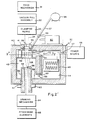
- FIGS. 2-7 An apparatus specifically designed to carry out the process of the present invention is disclosed in FIGS. 2-7 and is shown most comprehensively in a modified schematic manner in Figure 2.
- the furnace of the present invention is disclosed in unique combination with other elements and in configuration adapted to utilize the special properties of forced convection in a glass drawing operation.
- the application of the forced convection heating to the glass drawing art have resulted in extraordinary, unexpected, and surprising increase in the diameter capacity, drawing rate and quality (in terms of product rejection rates) of this art.
- the general combination as illustrated in Figure 2 and indicated generally by the numeral 30, includes a complex of feed mechanisms 31, preferably having a capacity for differential feeding of various components of a composite preform.
- the feeding complex may include a vacuum pull assembly 32 including the required gas tight seals, and clamping means 33.
- the workpiece of the apparatus is a heat softenable, drawable preform 34.
- this embodiment includes a hollow collar 35 or thermal isolator which is supplied with relatively constant temperature air from a source 36 via a conduit 37 with controllable valve 38.
- pre-cooling air is directed inwardly toward the preform through a plurality of inwardly facing, radially directed apertures such as 39. It has been successful and convenient to choose, as a standard, a temperature near room temperature of 70°F (about 21°C). To achieve a finer degree of control over keeping the preform temperature constant, temperature sensors above and/or below the collar could be provided to control pre-cooling air temperature and/or volume.
- the preform 34 is fed into the furnace 40 through a drawing chamber inlet 41.
- This inlet is preferably supplied with diameter adjusting means 42 such as a fairly refractory "iris" assembly, to ensure moderate resistance to heat loss.
- the drawing chamber 43 is one of two chambers which this embodiment of the furnace comprehends, the other chamber being the separate air heating chamber 44.
- the heating chamber is supplied with heating means which may be combustive, inductive, arc-induced, diaelectric, etc., but in the preferred embodiment comprised large area resistive coils 45. These are supplied with power from a source 46 and a control mechanism 47 such as variable impedance or a variable transformer.
- a forced convection element 50 (a high temperature fan, pump, etc.) draws air through the heating elements and direct a flow through a channel 51 which communicates with the drawing chamber 43. This delivery is preferably mediated by a distribution means 52 such as an internally, radially perforated plenum.
- a temperature sensing transducer means 54 is provided sending its signal to a central control system 60.
- the flow of air is actively or passably drawn past the preform/workpiece to create the working zone 55 terminating at or near the effective drawing chamber outlet 56.
- the flow continues through a return channel 57 which may be provided with a return forced convection element 58 and a return air temperature sensing transducer means 59 also sending to the central control 60.
- the effective drawing chamber outlet may be provided with diameter adjusting means 59 similar to the means 42 at the inlet.
- the effective drawing chamber outlet 56 is distinguished from the actual outlet 61 by an insulating sleeve 62 which movably engages the actual outlet and extends into the drawing chamber toward the inlet 41.
- an insulating sleeve 62 which movably engages the actual outlet and extends into the drawing chamber toward the inlet 41.
- This movable point thus defines the end of the working zone 55.
- the position of the sleeve may be temporarily fixed as by set screws or clamps, or may be under variable central control effected by extension means 63 such as servo-activated rack and gear or friction wheels.
- the product is drawn in the usual manner by a drawing mechanism 64 which employs gravity, traction means, etc.
- the product is then passed on to further processing elements 65: take-up reels, cutters, bundlers, slicers, etc.
- An effective pre-cooling collar 35 may be constructed as detailed in Figure 3. Compressed air of relatively constant temperature is brought via a conduit 37 from a constant temperature air source such as an air compressor into the collar and is directed inward toward the preform through radial apertures 39.
- a constant temperature air source such as an air compressor
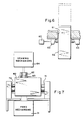
- FIG. 4 The detailed view in Figure 4 looking down on the drawing chamber inlet illustrates an embodiment of an adjustable diameter means 42 for causing the effective inlet diameter to approximate that of the preform 34 (shown as a typical single cladding fiber-optic preform.)
- a similar mechanism can be used for the diameter adjusting mechanism 59 of the effective outlet 56.
- Figure 5 shows a detailed horizontal section on the line V-V of Figure 2 of a flow distribution means 52 embodied in a toroidal plenum with internal radial perforations 53 shaped to facilitate flow control.
- the perforations would be elongated along the axis of the workpiece.
- FIG. 6 A detail of a dynamic embodiment of the adjustable sleeve 62 is shown in Figure 6 with an adjustment for a shortening of the working zone in broken lines. Adjustment is made by extending means 63 under central control 60.
- the extending means are preferably annular.
- the apparatus may be built with a symmetry about a central horizontal plane.
- the input channel from the heating chamber to the drawing chamber, as well as the flow distribution means may be located centrally.
- the "inlet” and “outlet” areas of the drawing chamber may then be identically supplied with closable return channels, extendable insulated sleeves, pre-cooling collars, and aperture diameter adjusting means. In this way the preform may be fed and the product drawn upward or downward with equal ease. The choice will depend upon the character of preform, product, and production rate.
- a typical product rejection rate of about 20% at each step of a multi-step manufacturing process obtains in present radiation furnaces.
- the process and apparatus of the present invention have significantly reduced this rejection rate.
- the drawing rate for moderate diameter products has been greatly limited by the need for a slow enough rate to allow complete and reasonably uniform heating of the preform.
- the present process heats even large diameter preforms quickly and uniformly to the point that some product can be taken up at rates 5-6 times to that of conventionally configured drawing furnaces, with more than satisfactory quality.
- the present process does not generally require special treatment of products which incorporate radiation absorbing claddings and fibers as compared to with the treatment required of such products in radiative furnaces.
- Such products include most composite image manipulating products: faceplates, image expanders, inverters, etc.
- the normal composite product is produced in several stages. This is due to limitations in the size of the reduction ratio of the product to preform which can be achieved without distortion. There has also been an absolute size limit of the preform that can be heated with threshhold uniformity.
- the present process can uniformly heat the working zone of a preform, including a composite preform, of at least up to 4.5 inches (12 cm) and possibly much larger. This means:
Landscapes
- Engineering & Computer Science (AREA)
- Chemical & Material Sciences (AREA)
- Life Sciences & Earth Sciences (AREA)
- General Life Sciences & Earth Sciences (AREA)
- Geochemistry & Mineralogy (AREA)
- Manufacturing & Machinery (AREA)
- Materials Engineering (AREA)
- Organic Chemistry (AREA)
- Physics & Mathematics (AREA)
- Thermal Sciences (AREA)
- Manufacture, Treatment Of Glass Fibers (AREA)
- Blow-Moulding Or Thermoforming Of Plastics Or The Like (AREA)
Abstract
Claims (22)
- Un dispositif pour étirer une préforme de matériaux optiques à ramollissement thermique et étirables en un produit optique de fibres ou de faisceaux de fibres, comprenant: un four (40) possédant une chambre d'étirage (43) avec un orifice d'entrée (41), un orifice de sortie (56) et une zone de traitement d'une préforme (55) située entre les deux; un mécanisme de chargement de la préforme (31), destiné à charger la préforme (34) dans l'orifice d'entrée (41); et un mécanisme d'étirage du produit (64) destiné à sortir le produit de l'orifice de sortie (56), caractérisé en ce que le four (40) comprend en outre une chambre de chauffage d'un fluide (44) contenant des moyens de chauffage d'un fluide gazeux (45), ces moyens de chauffage (45) étant pourvus d'une protection radiative pratiquement complète par rapport à la zone de traitement de la préforme (55), ainsi qu'un élément à convection forcée (50) pour décharger du fluide de la chambre de chauffage (44) dans la chambre d'étirage (43), de sorte que la préforme est chauffée dans la chambre d'étirage (43) essentiellement par la chaleur de convection.
- Un dispositif selon la revendication 1, possédant des moyens (35, 36, 37, 38, 39) destinés à porter la préforme (34) à une température normalisée à l'orifice d'entrée de la chambre d'étirage (41).
- Un dispositif selon la revendication 2, dans lequel les moyens destinés à porter la préforme (34) à une température normalisée comprennent une source de fluide (36) connectée par un conduit (37) à un collier (35) autour de l'orifice d'entrée de la chambre d'étirage (41), le collier (35) possédant des ouvertures dirigées vers l'intérieur (39).
- Un dispositif selon l'une quelconque des revendications précédentes, comportant une gaine isolée (62) s'étendant de l'orifice de sortie de la chambre d'étirage (56) vers l'orifice d'entrée de la chambre d'étirage (41) et dont l'extension par rapport à ceux-ci peut être ajustée, la gaine formant un orifice de sortie effectif de la zone de traitement de la préforme (55) du produit étiré.
- Un dispositif selon l'une quelconque des revendications précédentes, dans lequel des moyens de mesure de la température (54, 59) sont agencés dans le flux du fluide chauffé.
- Un dispositif selon la revendication 5, dans lequel un mécanisme de réglage central (60) est connecté en service aux moyens de mesure de la température (54, 59) en vue de régler les moyens de chauffage du fluide (45) et l'élément à convection forcée (50) et, par l'intermédiaire de ceux-ci, de régler la chaleur fournie par le flux du fluide de chauffage à la préforme (34).
- Un dispositif selon la revendication 6, dans lequel le mécanisme de réglage central (60) est connecté en service au moyen (63) servant à ajuster l'extension de la gaine isolée (62) et sert au réglage de celui-ci.
- Un dispositif selon l'une quelconque des revendications précédentes, dans lequel la préforme (34) est composée d'un faisceau d'éléments, le dispositif englobant une enveloppe étanche aux gaz et à vide entourant la préforme (34).
- Un dispositif selon l'une quelconque des revendications précédentes, dans lequel les éléments composant le four (40) sont répartis symétriquement autour d'un plan horizontal, la préforme (34) pouvant ainsi être respectivement chargée et le produit pouvant être retiré ou bien à partir de l'orifice d'entrée (41) ou bien à partir de l'orifice de sortie (56).
- Un dispositif selon les revendications 4 et 9, comportant une gaine isolée s'étendant de l'orifice d'entrée de la chambre d'étirage (41) vers l'orifice de sortie de la chambre d'étirage (56).
- Un dispositif selon l'une quelconque des revendications précédentes, dans lequel le mécanisme d'alimentation (31), le four (40) et le mécanisme d'étirage (64) sont montés sur des balanciers, l'ensemble de l'assemblage pouvant ainsi pivoter dans un plan vertical.
- Un procédé d'étirage d'un produit de fibres ou de faisceaux de fibres à partir d'une préforme de matériau à ramollissement thermique, étirable, comprenant les étapes suivantes: chargement de la préforme (34) à travers un orifice d'entrée (41) d'une chambre d'étirage (43) vers une zone de traitement de la préforme (55); chauffage de la préforme (34) dans la zone de traitement (55) jusqu'à ce que la température de la préforme (34) correspond à une température d'étirage dans la zone de traitement (55); et étirage du produit de la préforme (34) à travers un orifice de sortie de la chambre d'étirage (43), caractérisé en ce qu'un fluide gazeux est chauffé à une température correspondant à la température d'étirage de la préforme (34) ou supérieure à celle-ci, avec utilisation de moyens de chauffage (45), pourvus d'une protection radiative pratiquement complète par rapport à la zone de traitement de la préforme (55) et entraînant le fluide chauffé à passer près de la préforme (34) dans la zone de traitement (55), de sorte que la préforme (34) est chauffée dans la zone de traitement (55) essentiellement par la chaleur de convection.
- Un procédé selon la revendication 12, dans lequel le fluide est chauffé dans une chambre de chauffage séparée (44) et déchargé activement dans la chambre d'étirage (43).
- Un procédé selon les revendications 12 ou 13, dans lequel, après le passage du fluide chauffé près de la zone de traitement (55), le fluide est refoulé vers la chambre de chauffage (44) en vue d'un nouveau chauffage.
- Un procédé selon l'une quelconque des revendications 12 à 14, dans lequel la température du fluide chauffé est mesurée en un emplacement choisi, au moins à des intervalles de temps discrets, les valeurs de température mesurées étant utilisées pour ajuster la vitesse du chauffage du fluide et la vitesse de décharge du fluide chauffé dans la chambre d'étirage (43).
- Un procédé selon l'une quelconque des revendications 12 à 15, dans lequel une partie de la préforme (34), autour de l'entrée de la chambre d'étirage (43), est portée à une température de commande présélectionnée.
- Un procédé selon l'une quelconque des revendications 12 à 16, dans lequel la zone de traitement (55) est formée par introduction d'une gaine d'isolation (62), à partir de l'orifice de sortie (56) de la chambre d'étirage (43), pour constituer un orifice de sortie effectif au-dessous duquel le produit étiré est isolé du flux de fluide chauffé.
- Un procédé selon l'une quelconque des revendications 12 à 17, dans lequel la préforme (34) est chargée vers le haut, à partir du dessous de la chambre d'étirage (43), le produit étant étiré vers le haut, à partir du dessus de la chambre d'étirage (43).
- Un procédé selon l'une quelconque des revendications 12 à 18, dans lequel la préforme (34) est composée d'un faisceau d'éléments étirables.
- Un procédé selon la revendication 19, dans lequel le faisceau est enfermé dans une enveloppe étanche aux gaz, le procédé comprenant en outre l'étape d'application d'un vide au faisceau pendant l'étirage du produit.
- Un procédé selon les revendications 19 ou 20, dans lequel une préforme (34) est formée avec une section d'une dimension légèrement supérieure à la dimension finale désirée du produit, et dans lequel le produit est étiré de façon juste suffisante pour faire fondre le faisceau en une masse intégrale, exempte de vides.
- Un procédé selon l'une quelconque des revendications 19 à 21, dans lequel le faisceau est tordu à un angle présélectionné pendant l'étirage du produit de la préforme.
Priority Applications (2)
| Application Number | Priority Date | Filing Date | Title |
|---|---|---|---|
| AT87905325T ATE94158T1 (de) | 1987-06-26 | 1987-06-26 | Ofen und glasstreckverfahren. |
| DE19873787380 DE3787380T2 (de) | 1987-06-26 | 1987-06-26 | Ofen und glasstreckverfahren. |
Applications Claiming Priority (1)
| Application Number | Priority Date | Filing Date | Title |
|---|---|---|---|
| PCT/US1987/001557 WO1988010241A1 (fr) | 1987-06-26 | 1987-06-26 | Four et procede d'etirage du verre |
Publications (3)
| Publication Number | Publication Date |
|---|---|
| EP0370001A1 EP0370001A1 (fr) | 1990-05-30 |
| EP0370001A4 EP0370001A4 (en) | 1990-10-10 |
| EP0370001B1 true EP0370001B1 (fr) | 1993-09-08 |
Family
ID=22202444
Family Applications (1)
| Application Number | Title | Priority Date | Filing Date |
|---|---|---|---|
| EP87905325A Expired - Lifetime EP0370001B1 (fr) | 1987-06-26 | 1987-06-26 | Four et procede d'etirage du verre |
Country Status (3)
| Country | Link |
|---|---|
| EP (1) | EP0370001B1 (fr) |
| KR (1) | KR890701488A (fr) |
| WO (1) | WO1988010241A1 (fr) |
Families Citing this family (4)
| Publication number | Priority date | Publication date | Assignee | Title |
|---|---|---|---|---|
| JP5624796B2 (ja) | 2010-04-30 | 2014-11-12 | 株式会社フジクラ | 光ファイバ素線の製造装置及び製造方法 |
| US10941472B2 (en) | 2016-01-08 | 2021-03-09 | Metal Morphing Technologies, Inc. | Systems and methods for drawing high aspect ratio metallic glass-based materials |
| WO2017120123A1 (fr) * | 2016-01-08 | 2017-07-13 | Metal Morphing Technologies, Inc. | Systèmes et procédés d'étirage de matériaux à base de verre métallique à facteur de forme élevé |
| JP2017171549A (ja) * | 2016-03-25 | 2017-09-28 | 信越化学工業株式会社 | 光ファイバプリフォームの絞り加工方法及び加工装置 |
Family Cites Families (16)
| Publication number | Priority date | Publication date | Assignee | Title |
|---|---|---|---|---|
| BE522519A (fr) * | 1952-09-05 | |||
| NL261074A (fr) * | 1958-08-11 | |||
| US3119678A (en) * | 1960-11-18 | 1964-01-28 | American Optical Corp | Method of forming multifiber structure |
| US3328143A (en) * | 1962-01-24 | 1967-06-27 | American Optical Corp | Method of making light-conducting optical multifiber structures |
| US4127398A (en) * | 1963-09-18 | 1978-11-28 | Ni-Tec, Inc. | Multiple-channel tubular devices |
| US3654680A (en) * | 1969-04-28 | 1972-04-11 | Owens Illinois Inc | Method of making gas discharge device |
| US3622292A (en) * | 1969-06-03 | 1971-11-23 | Weston Instruments Inc | Tube uniting with fusion barrier |
| FR2288958A1 (fr) * | 1974-10-21 | 1976-05-21 | Desmarquest & Cec | Installation pour le traitement par zone de produits de forme allongee |
| GB1523595A (en) * | 1975-10-31 | 1978-09-06 | Nat Res Dev | Electrical resistance furnaces |
| DE2614631A1 (de) * | 1976-04-05 | 1977-10-13 | Siemens Ag | Verfahren zur herstellung von gradientenfasern |
| US4030901A (en) * | 1976-07-19 | 1977-06-21 | Bell Telephone Laboratories, Incorporated | Method for drawing fibers |
| DE2817651A1 (de) * | 1978-04-21 | 1979-10-31 | Siemens Ag | Verfahren zur erhoehung der bruchfestigkeit von glasfasern |
| JPS57100933A (en) * | 1980-12-12 | 1982-06-23 | Nippon Telegr & Teleph Corp <Ntt> | Preparation of base material for optical fiber |
| US4383843A (en) * | 1981-09-16 | 1983-05-17 | Western Electric Company, Inc. | Methods of and apparatus for heating a preform from which lightguide fiber is drawn |
| FR2563826B1 (fr) * | 1984-05-07 | 1991-08-30 | Verre Fluore Sa | Procedes de fabrication de fibres et de composants optiques en verres fluores et appareils destines a les mettre en oeuvre |
| US4578098A (en) * | 1984-06-15 | 1986-03-25 | At&T Technologies, Inc. | Apparatus for controlling lightguide fiber tension during drawing |
-
1987
- 1987-06-26 EP EP87905325A patent/EP0370001B1/fr not_active Expired - Lifetime
- 1987-06-26 WO PCT/US1987/001557 patent/WO1988010241A1/fr not_active Ceased
- 1987-06-26 KR KR1019890700349A patent/KR890701488A/ko active Granted
Also Published As
| Publication number | Publication date |
|---|---|
| EP0370001A4 (en) | 1990-10-10 |
| KR890701488A (ko) | 1989-12-20 |
| EP0370001A1 (fr) | 1990-05-30 |
| WO1988010241A1 (fr) | 1988-12-29 |
Similar Documents
| Publication | Publication Date | Title |
|---|---|---|
| KR950000625B1 (ko) | 유리연신공정 및 노 | |
| US4673427A (en) | Method of and device for drawing an optical fiber from a solid preform consisting substantially of SiO2 and doped SiO2 | |
| DE69815853T2 (de) | Vorrichtung und verfahren zum ummanteln eines vorformstabes für optische fasern und verfahren zum ziehen von optischen fasern | |
| US6536240B1 (en) | Method of making an optical fiber preform via multiple plasma depositing and sintering steps | |
| US4265649A (en) | Method for preparing a preform for optical waveguides | |
| US4925473A (en) | Process and furnace for heat application | |
| JPH07223832A (ja) | ガラス物品およびファイバオプティック・カプラの作成方法 | |
| AU741066B2 (en) | Method and apparatus for cooling optical fibers | |
| GB925335A (en) | Improvements in method of, and apparatus for, manufacturing light conducting devices | |
| JP4375902B2 (ja) | 光ファイバープレフォームの製造方法 | |
| JPS6044259B2 (ja) | オプチカルフアイバ製造方法 | |
| EP0881196B1 (fr) | Procédé d'étirage d'une boule de verre à une barre | |
| CN1331789C (zh) | 玻璃处理方法及用于该方法的玻璃处理设备 | |
| US4778501A (en) | Process and furnace for heat application | |
| WO1988010241A1 (fr) | Four et procede d'etirage du verre | |
| CA1315987C (fr) | Procede d'etirage du verre, et fourneau connexe | |
| AU5707500A (en) | Optical fiber drawing method and drawing device | |
| JPS63195139A (ja) | ガラスロツド延伸装置 | |
| IL83030A (en) | Glas drawing process and furnace | |
| EP1035082B1 (fr) | Procédé et dispositif de frittage d'une préforme de verre poreux | |
| CN1024181C (zh) | 玻璃预制棒的拉制工艺设备 | |
| JPS5826045A (ja) | 光フアイバの製造方法および装置 | |
| KR101169470B1 (ko) | 다공질 유리 모재의 소결 방법 및 소결 장치 | |
| JP2557673B2 (ja) | ガラス引き方法及び炉 | |
| US5320660A (en) | Method of manufacturing an optical fibre |
Legal Events
| Date | Code | Title | Description |
|---|---|---|---|
| PUAI | Public reference made under article 153(3) epc to a published international application that has entered the european phase |
Free format text: ORIGINAL CODE: 0009012 |
|
| 17P | Request for examination filed |
Effective date: 19900126 |
|
| AK | Designated contracting states |
Kind code of ref document: A1 Designated state(s): AT BE CH DE FR GB IT LI LU NL SE |
|
| RAP1 | Party data changed (applicant data changed or rights of an application transferred) |
Owner name: INCOM, INC. |
|
| A4 | Supplementary search report drawn up and despatched |
Effective date: 19900820 |
|
| AK | Designated contracting states |
Kind code of ref document: A4 Designated state(s): AT BE CH DE FR GB IT LI LU NL SE |
|
| 17Q | First examination report despatched |
Effective date: 19911211 |
|
| GRAA | (expected) grant |
Free format text: ORIGINAL CODE: 0009210 |
|
| AK | Designated contracting states |
Kind code of ref document: B1 Designated state(s): AT BE CH DE FR GB IT LI LU NL SE |
|
| PG25 | Lapsed in a contracting state [announced via postgrant information from national office to epo] |
Ref country code: IT Free format text: LAPSE BECAUSE OF FAILURE TO SUBMIT A TRANSLATION OF THE DESCRIPTION OR TO PAY THE FEE WITHIN THE PRE;WARNING: LAPSES OF ITALIAN PATENTS WITH EFFECTIVE DATE BEFORE 2007 MAY HAVE OCCURRED AT ANY TIME BEFORE 2007. THE CORRECT EFFECTIVE DATE MAY BE DIFFERENT FROM THE ONE RECORDED.SCRIBED TIME-LIMIT Effective date: 19930908 Ref country code: CH Effective date: 19930908 Ref country code: AT Effective date: 19930908 Ref country code: BE Effective date: 19930908 Ref country code: FR Effective date: 19930908 Ref country code: SE Effective date: 19930908 Ref country code: LI Effective date: 19930908 |
|
| REF | Corresponds to: |
Ref document number: 94158 Country of ref document: AT Date of ref document: 19930915 Kind code of ref document: T |
|
| REF | Corresponds to: |
Ref document number: 3787380 Country of ref document: DE Date of ref document: 19931014 |
|
| REG | Reference to a national code |
Ref country code: CH Ref legal event code: PL |
|
| EN | Fr: translation not filed | ||
| PG25 | Lapsed in a contracting state [announced via postgrant information from national office to epo] |
Ref country code: LU Free format text: LAPSE BECAUSE OF NON-PAYMENT OF DUE FEES Effective date: 19940630 |
|
| PLBE | No opposition filed within time limit |
Free format text: ORIGINAL CODE: 0009261 |
|
| STAA | Information on the status of an ep patent application or granted ep patent |
Free format text: STATUS: NO OPPOSITION FILED WITHIN TIME LIMIT |
|
| 26N | No opposition filed | ||
| REG | Reference to a national code |
Ref country code: GB Ref legal event code: IF02 |
|
| PGFP | Annual fee paid to national office [announced via postgrant information from national office to epo] |
Ref country code: GB Payment date: 20020626 Year of fee payment: 16 |
|
| PGFP | Annual fee paid to national office [announced via postgrant information from national office to epo] |
Ref country code: DE Payment date: 20020702 Year of fee payment: 16 |
|
| PG25 | Lapsed in a contracting state [announced via postgrant information from national office to epo] |
Ref country code: GB Free format text: LAPSE BECAUSE OF NON-PAYMENT OF DUE FEES Effective date: 20030626 |
|
| PGFP | Annual fee paid to national office [announced via postgrant information from national office to epo] |
Ref country code: NL Payment date: 20030630 Year of fee payment: 17 |
|
| PG25 | Lapsed in a contracting state [announced via postgrant information from national office to epo] |
Ref country code: DE Free format text: LAPSE BECAUSE OF NON-PAYMENT OF DUE FEES Effective date: 20040101 |
|
| GBPC | Gb: european patent ceased through non-payment of renewal fee |
Effective date: 20030626 |
|
| PG25 | Lapsed in a contracting state [announced via postgrant information from national office to epo] |
Ref country code: NL Free format text: LAPSE BECAUSE OF NON-PAYMENT OF DUE FEES Effective date: 20050101 |
|
| NLV4 | Nl: lapsed or anulled due to non-payment of the annual fee |
Effective date: 20050101 |