EP0370076B1 - Mastaufbau mit völlig freier hubhöhe - Google Patents
Mastaufbau mit völlig freier hubhöhe Download PDFInfo
- Publication number
- EP0370076B1 EP0370076B1 EP89901967A EP89901967A EP0370076B1 EP 0370076 B1 EP0370076 B1 EP 0370076B1 EP 89901967 A EP89901967 A EP 89901967A EP 89901967 A EP89901967 A EP 89901967A EP 0370076 B1 EP0370076 B1 EP 0370076B1
- Authority
- EP
- European Patent Office
- Prior art keywords
- carriage
- lift
- carriage lift
- uprights
- cylinder
- Prior art date
- Legal status (The legal status is an assumption and is not a legal conclusion. Google has not performed a legal analysis and makes no representation as to the accuracy of the status listed.)
- Expired
Links
Images




Classifications
-
- B—PERFORMING OPERATIONS; TRANSPORTING
- B66—HOISTING; LIFTING; HAULING
- B66F—HOISTING, LIFTING, HAULING OR PUSHING, NOT OTHERWISE PROVIDED FOR, e.g. DEVICES WHICH APPLY A LIFTING OR PUSHING FORCE DIRECTLY TO THE SURFACE OF A LOAD
- B66F9/00—Devices for lifting or lowering bulky or heavy goods for loading or unloading purposes
- B66F9/06—Devices for lifting or lowering bulky or heavy goods for loading or unloading purposes movable, with their loads, on wheels or the like, e.g. fork-lift trucks
- B66F9/075—Constructional features or details
- B66F9/08—Masts; Guides; Chains
-
- B—PERFORMING OPERATIONS; TRANSPORTING
- B66—HOISTING; LIFTING; HAULING
- B66F—HOISTING, LIFTING, HAULING OR PUSHING, NOT OTHERWISE PROVIDED FOR, e.g. DEVICES WHICH APPLY A LIFTING OR PUSHING FORCE DIRECTLY TO THE SURFACE OF A LOAD
- B66F9/00—Devices for lifting or lowering bulky or heavy goods for loading or unloading purposes
- B66F9/06—Devices for lifting or lowering bulky or heavy goods for loading or unloading purposes movable, with their loads, on wheels or the like, e.g. fork-lift trucks
- B66F9/075—Constructional features or details
- B66F9/20—Means for actuating or controlling masts, platforms, or forks
- B66F9/205—Arrangements for transmitting pneumatic, hydraulic or electric power to movable parts or devices
Definitions
- This invention relates to a full free lift mast assembly having first and second carriage lift jacks and a first mast lift jack, and more particularly to a full free lift mast assembly having first and second pairs of uprights, a carriage movably mounted on the second pair of uprights, first and second carriage lift jacks connected between the second pair of uprights and the carriage, a connecting arrangement for connecting the first and second carriage lift jacks to each other, and a mast lift jack connected between the first and second pair of uprights.
- Lift mast assemblies typically have a first pair of spaced apart uprights which are pivotally mounted to one end of a material handling vehicle and a second pair of spaced apart uprights which are mounted on the first pair of uprights and guided by the first pair of uprights for extensible movement relative thereto.
- Such lift mast assemblies have a carriage which is mounted on the second pair of uprights and elevationally movable therealong for lifting a load.
- Lift mast assemblies of this type normally have a plurality of lift chains which transfer motion from a mast lift jack to the carriage and elevationally move the carriage relative to the movable uprights.
- Chains of the type used in lift mast assemblies are normally provided in pairs. These chains cooperate with a carriage lift jack or mast lift jack to elevationally move the carriage along the second pair of uprights and the mast along the first pair of uprights.
- the chains have a tendency to become unevenly adjusted in length as normal wear of the chain and cooperating component parts occur. This wear is usually a result of chain loading and the considerable number of operational cycles the chain must endure during normal operation. This uneven adjustment in the chains will result in cocking of the carriage and/or second pair of uprights relative to the uprights upon which it rides and cause undesirable side loading of the carriage, uprights, jacks and associated componentry.
- Cocking of the carriage due to uneven chain length, will also cause greater frictional forces to occur at the carriage rollers. This will increase the amount of horsepower required to elevate the carriage and reduce the efficiency of operation of the lift system. Excessive carriage cocking will make it difficult for the operator to align the forks mounted on the carriage with the load to be lifted. During lifting of the load, the cocking of the carriage will cause the load to be at an angle of inclination in a direction traverse the pair of uprights. The added weight of the load on the carriage will serve to increase carriage side loading and premature wear and failure of the associated componentry.
- an additional lift jack (a carriage lift jack) which is mounted on the on the second pair of uprights is required.
- This carriage lift jack cooperates with the lift chains to cause the lift chains to move at a ratio of two to one and move the carriage along the second pair of uprights without requiring any of the extension of the second pair of uprights relative to the first pair of uprights. This is important especially in areas wherein overhead clearances are low and elevation of the carriage assembly without elevation of the movable uprights is a necessity. This, of course, clutters up the lift mast assembly between the spaced apart second pair of uprights (window) and further reduces visibility of the vehicle operator.
- the ′893 patent discloses the use of a mast lift jack with a ported rod for delivering pressurized fluid flow to the carriage lift jacks. Leakage fluid passing from the rod end of the carriage lift jacks to the head end of the carriage lift jacks would result in impaired operation of the carriage lift jacks and eventual uneven operation. If leakage past the piston should continue over a prolonged period of time and not be able to escape, the operation of the jack will diminish to the point where the stroke length will be drastically reduced. Thus, the free lift of the carriage will be reduced an equal amount.
- a full free lift mast assembly having first and second spaced apart uprights and a carriage movably mounted on the second pair of uprights.
- a first mast lift jack having a cylinder and a rod connected to an extensively movable relative to the cylinder has the rod connected to one of the first pair of fixed and movable uprights and the cylinder connected to the other of the first pair of fixed and movable uprights.
- a first carriage lift jack having a longitudinal axis, a cylinder, and a rod connected to an extensibly movable along the longitudinal axis and relative to the first carriage lift jack cylinder is pivotally connected at the first carriage lift jack rod to one of the carriage and second pair of uprights.
- a second carriage lift jack having a cylinder, a longitudinal axis and a rod connected to an extensively movable relative to the second carriage lift jack cylinder is provided.
- the second lift jack rod is pivotally connected to the other end of the carriage and the second uprights.
- a first means is provided for connecting the first carriage lift jack cylinder to the second carriage lift jack cylinder and for maintaining the first and second carriage lift jack cylinders from movement relative to each other and for maintaining the longitudinal axis of the first and second carriage lift jacks substantially parallel to each other.
- the full free lift mast assembly of the subject invention provides a unique solution to the problem of full free lift by utilizing a pair of carriage lift jacks in an overlapping fashion so that full free lift may be achieved.
- the first connecting means enables a pair of carriage lift jacks (first and second carriage lift jacks) to be utilized by maintaining the first and second carriage lift jacks from movement relative to each other and the longitudinal axis of the first and second carriage lift jacks parallel to each other.
- bending, relative movement, and the like of the first and second carriage lift cylinders is reduced to a minimum which enables the first and second carriage lift cylinders to be used.
- the combined extended length of the overlapped first and second carriage lift jacks is of a magnitude sufficient to move the carriage to a location adjacent a lower end portion of the second pair of uprights and to a location adjacent the upper end portion of the second pair of uprights the problem associated with the inability of prior chainless lift masts from achieving full free lift is overcome.
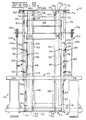
- a lift mast assembly 10 has a first pair of spaced apart uprights 12 having upper and lower end portions 14,16 which are pivotally connected at the lower end portion 16 to the front end portion 18 of the lift truck 20.
- the lift mast assembly 10 also has a second pair of spaced apart uprights 22 which are mounted on the first pair of spaced apart uprights 12 and guided by the first pair of spaced uprights 12 for elevational movement between extended and retracted positions relative to the first pair of spaced apart uprights 12.
- the second pair of spaced apart uprights 22 are nested between the first pair of spaced apart uprights 12.
- the second pair of spaced apart uprights 22 each have upper and lower end portions 24 and 26.
- the upper end portion 14 of the first pair of spaced apart uprights are connected together by a cross tie member 28 and the lower end portion 16 of the first pair of spaced apart uprights 12 are connected by a lower cross tie member 30.
- the first pair of spaced apart uprights 12 are maintained by the upper and lower cross tie members 28,30 parallel to one another.
- the upper end portion 24 of the second pair of spaced apart uprights 22 is connected together by an upper cross tie member 32 and the lower end portion 26 of the second pair of spaced apart uprights 22 is connected by a lower cross tie member 34.
- the upper and lower cross tie members 32,34 maintain the second pair of spaced apart uprights 22 parallel to each other.
- An upper cross beam member 36 is connected to the upper end portion 24 of the second pair of spaced apart uprights 22.
- the upper cross beam member 36 is provided for connecting a plurality of lift jacks 54,56,64,68 to be hereinafter discussed, to the pair of spaced apart uprights 22.
- the second pair of spaced apart uprights 22 are guided for movement relative to the first pair of spaced apart uprights 12 by a plurality of rollers 38 in a conventional manner.
- a carriage 40 having spaced apart upper and lower carriage plate members 42,44 and the first and second spaced apart roller brackets 46,48 which are connected to the upper and lower carriage plate members 42,44 is provided.
- the roller brackets 46,48 extend from the upper and lower carriage plate members 42,44 and include a plurality of rollers 50 connected thereto for guiding the carriage for elevational movement along the second pair of spaced apart uprights 22.
- the carriage has a pair of L shaped forks 52 which are connected to the upper and lower carriage plate members 42,44 and movable with the carriage 40.
- the forks 52 are mounted on the carriage 40 in such a manner so as to permit side adjustment thereof.
- the carriage 40 is elevationally movable along the second pair of spaced apart uprights 22 between the end portions 24,26 thereof.
- First and second mast lift jacks 54,56 each having a cylinder 58 are mounted at the cylinder 58 on the first pair of uprights 12 at the lower end portion 16 thereof and extend substantially parallel to the first pair of spaced apart uprights 12.
- the cylinders 58 of the first and second lift jacks 54,56 each have a rod 60 connected to the cylinder 58 and extensibly movable along a longitudinal axis 62 of each of the cylinders 58 of the first and second mast lift jacks 54,56.
- the rods 60 of the first and second mast lift jacks 54,56 are connected to the upper cross beam member 36. Extension of the rods 60 will cause elevational movement of the first pair of spaced apart uprights 12 relative to the second pair of spaced apart uprights 22.
- the first mast lift jack 54 is mounted closely adjacent one of the uprights of the first pair of spaced apart uprights 12 and the second mast lift jack 56 is mounted closely adjacent the other of the uprights of the first pair of spaced apart uprights. Therefore, the visibility of the vehicle operator will be maximized since the window defined by the space between the first pair of spaced apart uprights 12 is as at a maximum for a given vehicle size and width.
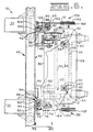
- First and second carriage lift jacks 64,66 and third and fourth carriage lift jacks 68,70 are provided for elevationally moving the carriage along the second pair of spaced apart uprights 22 between a lowered position as shown in Figs. 1 and 2, wherein the carriage is adjacent the lower end portion 26 of the second pair of uprights 22, and a raised position spaced elevationally above and relative to the lower position, as shown in Figs. 3 and 4, at which the carriage is adjacent the upper end portion 24 of the second pair of spaced apart uprights.
- the first, second, third and fourth carriage lift jacks 64,66,68,70 provide this free lift without requiring extension of the second pair of spaced apart uprights 22 relative to the first pair of spaced apart uprights 12.
- the first carriage lift jack 64 has a longitudinal axis 72, a tubular cylinder 74, and a rod 76 which is connected to and extensibly movable along said longitudinal axis 72 and relative to the first carriage lift jack cylinder 74.
- the first carriage lift jack rod 76 is pivotally connected to the upper cross beam member 36 of the second pair of spaced apart uprights 22 by a bifurcated member and pin arrangement 78 of a conventional design.
- the second carriage lift jack 66 has a tubular cylinder 80, a longitudinal axis 82, and a rod 84 extensibly movable relative to the tubular cylinder 80 along the second carriage lift jack longitudinal axis 82.
- the rod 84 of the second carriage lift jack 66 is pivotally connected to the lower carriage plate member 44 by a bifurcated member and pin arrangement 86 of a conventional design.
- a first connecting means 88 is provided for connecting the first carriage lift jack cylinder 74 to the second carriage lift jack cylinder 80 and for maintaining the first and second carriage lift jack cylinders 74 and 80 from movement relative to each other and for maintaining the longitudinal axis 72,82 of the first and second carriage lift jacks 64,66 substantially parallel to each other. It is to be noted that the cylinders 74,80 of the first and second carriage lift jacks 64,66 overlap each other a preselected amount in order that the magnitude of the combined length of stroke of the rods 76,84 is adequate to provide full free lift of the carriage 40 relative to the second pair of spaced apart uprights 22.
- the amount of overlap of the cylinders 74,80 is determined as a function of the overall extended length of the first and carriage lift jacks 64,66, the design criteria of the carriage 40 (carriage roller spacing, roller bracket length, and location of the lower carriage plate member relative to the carriage rollers), the length of the second pair of spaced apart uprights, and the location of the pivotal connection of the rods 76 and 84 to the carriage 40, and second pair of uprights 22.
- the third and fourth carriage lift jacks 68,70 are constructed in a manner identical to that of the first and second carriage lift jacks 64 and 66.
- the third carriage lift jack has a longitudinal axis 90, a tubular cylinder 92 and a rod 94 slidably disposed in the tubular cylinder 92 and extensibly movable relative to the tubular cylinder 92 along the longitudinal axis 90.
- the fourth carriage lift jack 70 has a longitudinal axis 96, a tubular cylinder 98 and a rod 100 slidably disposed in the cylinder 98 and extensible relative to the cylinder 98 along the longitudinal axis 96.
- a bifurcated member and pin arrangement 102 which is of a conventional design pivotally connects the rod 94 of the third carriage lift jack 68 to the upper cross beam member 36 and a bifurcated member and pin arrangement 104 which is also of a conventional design pivotally connects the rod 100 to the lower carriage plate member 44.
- Extension of the rods 94 and 100 of the third and fourth carriage lift jack 68,70 will move the carriage 40 to the lowered position adjacent the lower end portion 26 of the second pair of uprights and retraction of the rods 94,100 will move the carriage 40 to the raised position adjacent the upper end portion 24 of the second pair of spaced apart uprights 22.
- first and second and third and fourth carriage lift jacks 64,66,68,70 provide full free lift of the carriage 40 along the second pair of spaced apart uprights 22 without requiring movement of the second pair of spaced apart uprights 22.
- the bifurcated member and pin arrangements 78,86,102,104 allow the first and second carriage lift jacks 64,66 and the third and forth carriage lift jacks 68,70 to self center during operation which reduces the potential for side loading of the jacks 64,66,68,70.
- the first, second, third and fourth carriage lift jacks 64,66,68,70 may be replaced by pairs of parallel carriage lift jacks, respectively, to further reduce the potential for side loading by equally distributing and balancing the load forces.
- the first connecting means 88 preferably includes a plurality of first tab members 106 which are welded to the first carriage lift jack cylinders 74 at preselected longitudinally aligned spaced apart locations along the first carriage lift jack 74.
- a plurality of second tab members 108 are welded to the second carriage lift jack cylinder 80 at preselected longitudinally aligned spaced apart locations along the second carriage lift jack cylinder 80.
- the first and second tab members 106,108 are in sequential and adjacent abutting contact with each other and provide a plurality of connections along each of the cylinders 74,80.
- a first fastening means 110 is provided for releasably fastening each one of the plurality of first tab members to an adjacent abutted one of each of the second tab members 108.
- the first fastening means 110 preferably includes a plurality of threaded fasteners 113 disposed in an apertures 111 of each of the first and second tab members 106,108 and securely connected thereto.
- the first and second plurality of tabs 106,108 and fastening means 110 will result in the sharing of torsional, linear, and couple loads applied to the cylinders 74,80 by each of the tabs 106,108.
- the first connecting means 88 also includes a plurality of third tab members 112 which are welded to the first carriage lift jack cylinder 74 at preselected longitudinally aligned spaced apart locations along the first carriage lift jack cylinder 74. Said third tab members 112 are circumferentially spaced from the first tab members 106 on the cylinder 74 of the first carriage lift jack 64. A plurality of fourth tab members 114 are welded to the second carriage lift jack cylinder 80 at preselected longitudinally aligned spaced apart locations along the second carriage lift jack 80. The fourth tab members 114 are circumferentially spaced from the second tab members 108 on the second carriage lift jack 80. The third and fourth tab members 112,114 are in sequential aligned and butting contact with each other.
- a second fastening means 116 is provided for releasably fastening each one of the plurality of third tab members 112 to an adjacent abutted one of the fourth tab members 114.
- the second fastening means 116 preferably includes a plurality of axially aligned apertures 118 which are disposed in the third and fourth tab members 112,114.
- a plane 120 passing longitudinally through the apertures 111 and 118 of the first, second, third and fourth tab members 106,108,112 and 114 is preferably parallel to the longitudinal axes 72,82 first and second cylinders 74,80 and extends between the first and second cylinders 74,80.
- the first, second, third, and forth tab members 106,108,112, and 114 together restrain the first and second cylinders from pivotal movement about the first and second fastening means 110,116.
- a second connecting means 122 is provided for connecting the cylinders 92,98 of the third and fourth carriage lift jacks 68,70 to one another and for maintaining the longitudinal axis 90,96 of the third and fourth carriage lift jacks 68,70 substantially parallel to each other and in a preselected overlapping relationship relative to each other, and for maintaining the cylinders 92,98 of the third and fourth carriage lift jacks 68,70 from movement relative to each other.
- the longitudinal axis 72,82,90 and 96 are preferably substantially parallel to each other so as to provide for smooth and parallel operation of the carriage 40 as it is guided along the second pair of spaced apart uprights 22.
- the second connecting means 122 is identical in construction to that of the first connecting means 88 and therefore, will not be discussed in any greater detail.
- the first and second carriage lift jacks 64,66 are spaced from the third and fourth carriage lift jacks 68,70 and located, relative to the first and second pairs of uprights 12,22 and window defined thereby, at positions wherein the the line of sight of the vehicle operator is not restricted by the carriage lift jacks 64,66,68,70.
- the location of the first and second carriage lift jacks 64,66 is adjacent one of the uprights of the first pair of uprights 12 and the location of the third and fourth carriage lift jacks 68,70 is adjacent the other upright of the first pair of uprights 12.
- first and second carriage lift jacks 64,66 are overlapped a preselected distance of their length in order that the combined length of the first and second carriage lift jacks 64,66 is of a magnitude sufficient to move the carriage 40 from the lowered position adjacent the lower end portion 26 of the second pair of uprights 22, when the rods 76,78 are extended, to the raised position adjacent the upper end portion 24 of the second pair of uprights 22, when the rods 76,78 are retracted.
- the overlap provided on the cylinders 92,98 of the third and fourth carriage lift jacks 68,70 is identical to that of the first and second carriage lift jacks 64,66 so that the combined extended length of the third and fourth carriage lift jacks 68,70 is of a magnitude sufficient to move the carriage 40 from a lowered position adjacent the lower end portion 26 of the second pair of uprights 22, with the rods 94,100 extended to a raised position adjacent the upper end portion 24 of the second pair of spaced apart uprights 22, with the rods 94,100 retracted.
- first and third carriage lift jack rods 76,94 extend from the cylinders 74,92, respectively, in the same and an upward direction relative to the uprights 12,22, and the second and fourth carriage lift jack rods 84,100 extend from the cylinders 80,98 in the same and a downward direction from the cylinders 80,98.
- first and second rods 76,84 extend in opposite directions from each other and the third and fourth rods 94,100 extend in opposite directions relative to each other.
- a first passage means 130 is provided for interconnecting the head end portions 126 of the first and second carriage lift jack cylinders 74,80 to each other and for passing leakage fluid from the head end portions 126 of the first and second carriage lift jack cylinders 74,80 to a reservoir 132.
- a second passage means 134 is provided for interconnecting the head end portions of the third and fourth carriage lift jacks cylinders 92,98 to each other and for passing leakage fluid from the head ends 126 of the third and fourth carriage lift jack cylinders 92,98 to the reservoir 132.
- each of the first and second mast lift jacks 54,56 have a piston 136 slidably disposed in the cylinder 58 and connected to the rod 60.
- the pistons 136 of the first and second mast lift jacks 54,56 each have a cross sectional diameter which is smaller in magnitude than the diameters of the pistons 128 of any one of the first, second, third and fourth carriage lift jacks 64,66,68 and 70. Therefore, the carriage lift jacks 64,66,68 and 70 will extend to lift the carriage 40 prior to extension of the mast lift jacks 54,56 to raise the second pair of uprights 22.
- the diameter of the piston 128 of the first, second, third and fourth carriage lift jacks 64,66,68,70 are equal in magnitude.
- the second and fourth carriage lift jacks 66,68 will retract to raise the carriage 40 prior to retraction of the first and third carriage lift jacks 64,68 since the first and third carriage lift jacks 64,68 must lift not only the weight of the carriage but also the additional weight of itself and the second and fourth carriage lift jacks 66,70. Therefore, raising of the carriage 40 will precede the raising of the second pair of uprights 22.
- the first and second passage means 130,134 include conduit assemblies 138 which pass drain fluid between the head ends 126.
- Flexible hoses 140 which are wound on a spool assemblies 142 deliver the drain fluid from the head ends 126 to a junction box 143 which tees the flexible hoses 140 to the reservoir 132.
- the first, second, third, and fourth carriage lift jacks 64,66,68,70 are single acting. Thus, these hoses 140 are not pressurized in order to extend the rods 76,84,94,100, gravity accomplishes this.
- pilot operated control valves 144,145 are provided to direct fluid flow between a source of pressurized fluid, such as first and second pumps 146,147 and the head end portions 135 of the first and second mast lift jacks 54,56, by conduit 141 and between the head end portions 135 of the first and second mast lift jacks 54,56 and the reservoir 132 by conduit 164.
- the first and second pilot operated control valves are shiftable between raise "R", at which pressurized fluid flow is delivered from a source of pressurized fluid such as pumps 146,147 to the head end portion 135 of the mast lift jacks 54,56, and lower "L", at which fluid flow in the first and second lift jacks 54,56 is directed to the reservoir 132 from the head end portion 135 of the mast lift jacks 54,56 .
- a spring centered neutral "N”, infinitely variable, pilot valve 148 which is manually shiftable between raise "R” and lower “L” positions is provided for selectively delivering pressurized fluid flow from a pilot pump 150 and shifting the first and second pilot operated control valves 144,145 between their raise “R” and lower “L” positions.
- the rods 60 of the first and second mast lift jacks 54,56 are ported, so that fluid at the head end portion 135 of the first and second mast lift jacks 54,56 is communicated along an axial passage in each of the rods 60 and in fluid communication with the rod end portions 124 of a respective one of the first and third carriage lift jack cylinders 74,92, by flexible conduits 152.
- the rod ends 124 of the cylinders 74,92 of the first and third lift jacks 64,68 are in fluid communication connection with the rod ends 124 of the cylinders 80,98, respectively, of the second and fourth carriage lift jacks 66,70 by conduits 154.
- fluid directed by the first and second pilot operated control valves 144,145 will pass through the ported rods 60 of the first and second mast lift jacks 54,56, the conduits 152,154 and between the rod ends 124 of the first and third carriage lift jacks 64,68 and the first and second pumps 146,147 and reservoir 132 as determined by the position of the pilot operated control valves 144,145.
- the sequencing as aforementioned will cause the first and third carriage lift jacks 64,68 to extend first, then the second and fourth carriage lift jacks 66,70, and finally the first and second mast lift jacks 54,56.
- the pilot control valve is shifted to the lowered position "L”. Fluid is then passed from the rod ends 124 of the first, second, third and fourth carriage lift jacks 64,66,68 and 70 and from the head end portions 135 of the first and second mast lift jacks 54,56 to reservoir 132.
- lowering of the first and second pairs of spaced apart uprights 22 and the carriage 40 will occur as this happens.
- a choke 155 in the form of a fixed orifice, and first and second check valves 156, 158 are provided as a design alternative in situations where the space available on the lift mast assembly 10 does not allow the difference of the diameters of the pistons 136,128 to be great enough in magnitude to accomplish the desired jack sequencing.
- the choke 155, and check 156 are disposed in a first branch conduit 160 and the check 156 is disposed in a second branch conduit 162 of conduit 164.
- Conduit 164 is connected to the rod end 137 of the mast lift jack cylinders 58, the first branch conduit is connected to the second control valve 145 and the second branch conduit 162 is connected to the first control valve 144.
- the choke 155, and checks 156,158 maintain a preselected amount of back pressure in the rod ends 137 (between the piston rod end side, cylinder wall, and cylinder rod end caps) of the cylinders 58 of the lift cylinders 54,56 during extension of the mast lift jacks 54,56 so that the proper sequencing may be maintained.
- first and second control valves 144,145 shifted to the raise positions "R"
- fluid flow is delivered to the head ends 135 of the first and second mast lift cylinders 54,56 to extend the rods 60 therefrom.
- the fluid in the rod ends 137 of the cylinders 58 is directed by conduits 164,160 and 162 toward the first and second control valves 144,145.
- the checks 156,158 prevent the fluid from flowing to the first and second control valves 144,145 and forces the flow through the restriction defined by the choke 155, through the second control valve 145, and to the reservoir 132.
- the carriage lift jacks 64,66,68,70 will extend prior to any extension of the mast lift jacks 54,56 and provide for full free lift of the carriage 40 before any extension of the second uprights 22.
- the full free lift mast assembly 10 is suitable for elevationally positioning a load relative to the vehicle 20 upon which the full free lift mast assembly 10 is pivotally mounted.
- the carriage 40 is at the lowered position adjacent the lower end portion 26 of the second pair of uprights 22.
- the forks 52 are adjacent an underlying vehicle supporting surface and suitable for picking up a palletized load (not shown) supported on the underlying surface.
- the vehicle 20 is then properly positioned so that the forks 52 are at a location adjacent the load and aligned with the load so that the forks 52 are positioned beneath the load to be lifted.
- the pilot control valve 148 Upon completion of this maneuver the pilot control valve 148 will be shifted by the vehicle operator to the "R" position to raise the load. This manipulation will cause shifting of the pilot control valves 144,145 to the raised positions "R”. Pressurized fluid flow will be directed by the pilot operated control valves 144,145 from the pumps 146,147, respectively, to the head ends 135 of the first and second mast lift jacks 54,56. The fluid delivered to the head ends 135 of the mast lift cylinders 58 will pass up the ported rods 60 and by conduits 152 to the first, second, third, and fourth lift jacks 64,66,68, and 70.
- Actuation of the first and second control valves 144,145 will result in retraction of rods 84 and 100 of the second and fourth carriage lift jacks 54,56 first and elevational movement of the carriage 40 toward the upper end portion 24 of the second pair of spaced apart uprights 22.
- fluid pressure will increase and the first and third carriage lift jacks 64,68 will be actuated and the rods 76,94 retracted.
- first and third carriage lift jacks 64,68 must, in addition to lifting the weight of the carriage 40 and the load carried thereby, lift the weight of the second and fourth lift jacks 66,70.
- the fluid pressure acting against the pistons 128 will cause the first, second, third and fourth carriage lift jacks 64,66,68 and 70 to retract and raise the carriage 40 to the uppermost position (Fig. 3) adjacent the upper end portion 24 of the second spaced apart uprights 22. This is achieved without requiring any extension of the second pair of uprights 22 relative to the first pair of uprights 12.
- first and second carriage lift jacks 64,66, and the third and fourth carriage lift jacks 68,70 are pivotally connected to the upper cross beam member 36 and the lower carriage plate member 44, as earlier described, the first, second, third and fourth carriage lift jacks 64,66,68,70 will be able to self center. This will reduce the potential for side loading of the first, second, third and fourth lift jacks 64,66,68 and 70 and result in reduced fluid leakage and premature ware of the carriage lift jacks 64,66,68,70.
- the first connecting means 88 will further improve the life of the first and second carriage lift jacks 64,66 by maintaining the axes 72,82 parallel to each other and thereby resist buckling, bending and the like.
- the first connecting means also maintains the first and second carriage lift jack cylinders 74,80 at a proper overlapped relationship relative to each other so that the amount of extension of the first and second carriage lift jack rods 76,84 is adequate to enable full free lift of the carriage 40.
- the second connecting means 122 is identical in constriction to that of the first connecting means 88 and will achieve identical results as that of the first connecting means 88 by maintaining the third and fourth carriage lift jacks axes 90,96 parallel to each other and maintaining the proper amount of longitudinal overlap of the third and fourth carriage lift jack cylinders 92,98 so that full free movement of the carriage 40 is permitted.
- the second passage means 134 is provided for draining leakage fluid from the head end portions 126 of the carriage lift jacks 64,66,68 and 70.
- the second passage means 134 interconnects the head end portions 126 of the first, second, third and fourth lift jacks 64,66,68,70 with the drain.
- the spool assemblies 142 take up any slack in the hose 140 as the carriage 40 moves along the second pair of uprights 22.
Landscapes
- Engineering & Computer Science (AREA)
- Transportation (AREA)
- Structural Engineering (AREA)
- Civil Engineering (AREA)
- Life Sciences & Earth Sciences (AREA)
- Geology (AREA)
- Mechanical Engineering (AREA)
- Chemical & Material Sciences (AREA)
- Combustion & Propulsion (AREA)
- Forklifts And Lifting Vehicles (AREA)
Claims (18)
ein erstes Paar von mit Abstand angeordneten aufrechten Elementen (12);
ein zweites Paar von mit Abstand angeordneten aufrechten Elementen (22) beweglich angeordnet an dem ersten Paar von aufrechten Elementen (12);
ein auf dem zweiten Paar von aufrechten Elementen (22) beweglich angeordneter Schlitten (40);
eine erste Masthubvorrichtung (54) mit einem Zylinder (58) und einer Stange (60) verbunden mit und ausfahrbar beweglich bezüglich des Zylinders (58) wobei die Stange (60) mit einem aufrechten Element des ersten Paars von festen (12) und beweglichen (22) aufrechten Elementen verbunden ist und wobei der Zylinder (60) mit dem anderen Element des ersten Paars von festen (12) und beweglichen (22) aufrechten Elementen verbunden ist;
eine erste Schlittenhubvorrichtung (64) mit einer Längsachse (72), einen Zylinder (74) und eine Stange (76) verbunden mit und ausfahrbar beweglich entlang der ersten Schlittenhubvorrichtungslängsachse (72) und relativ zu dem ersten Schlittenhubvorrichtungszylinder (74), wobei die erste Schlittenhubvorrichtunsstange (76) schwenkbar verbunden ist mit dem Schlitten (40) oder dem zweiten Paar von aufrechten Elementen (22);
eine zweite Schlittenhubvorrichtung (66) mit einem Zylinder (80), einer Längsachse (82) und einer Stange (84) verbunden mit und ausfahrbar bewegbar relativ zu dem zweiten Schlittenhubvorrichtungszylinder (80) entlang der zweiten Schlittenhubvorrichtungslängsachse (82), wobei die zweite Hubvorrichtungsstange (84) schwenkbar verbunden ist mit dem jeweils anderen Bauteil, d. h. Schlitten (40) oder dem zweiten Paar von aufrechten Elementen (22); und
erste Verbindungsmittel (88) zur Verbindung des ersten Schlittenhubvorrichtungszylinders (74) mit dem zweiten Schlittenhubvorrichtungszylinder (80) und zur Beibehaltung der ersten und zweiten Schlittenhubvorrichtungszylinder (74, 80) gegenüber einer Bewegung relativ zueinander in einer vorgewählten, überlappenden Beziehung relativ zueinander und zur Aufrechterhaltung der Längsachse (72, 82) der ersten und zweiten Schlittenhubvorrichtungen (64, 66) im wesentlichen parallel zueinander.
eine Vielzahl von ersten Ansatzgliedern (106) verbunden mit dem ersten Schlittenhubvorrichtungszylinder (74) an vorgewählten mit Längsabstand angeordneten ausgerichteten mit Abstand angeordneten Stellen entlang des ersten Schlittenhubvorrichtungszylinders (74);
eine Vielzahl von zweiten Ansatzgliedern (108) verbunden mit dem zweiten Schlittenhubvorrichtungszylinder (80) an vorgewählten in Längsrichtung ausgerichteten mit Abstand angeordneten Stellen entland des zweiten Schlittenhubvorrichtungszylinders (80), wobei die ersten und zweiten Ansatzglieder (106, 108) in sequentiellem und benachbarten anstoßenden kontakt miteinander stehen, und
erste Befestigungsmittel (110) zur lösbaren Befestigung eines jeden der Vielzahl von ersten Ansatzgliedern (106) an einem benachbarten anstoßenden der zweiten Ansatzglieder (108).
eine Vielzahl von dritten Ansatzgliedern (112) verbunden mit dem Zylinder (74) der ersten Schlittenhubvorrichtung (64) an vorgewählten mit Längsabstand angeordneten ausgerichteten Stellen entlang des ersten Schlittenhubvorrichtungszylinders (74), wobei die dritten Ansatzglieder (112) umfangsmäßig mit Abstand angeordnet sind gegenüber den ersten Ansatzgliedern (106) und zwar auf dem ersten Schlittenhubvorrichtungszylinder (74),
und eine Vielzahl von vierten Ansatzgliedern (114) verbunden mit dem Zylinder (80) der zweiten Schlittenhubvorrichtung (66) an vorgewählten in Längsrichtung mit Abstand angeordneten ausgerichteten Stellen entlang des zweiten Schlittenhubvorrichtungszylinders (80), wobei die vierten Ansatzglieder (114) umfangsmäßig mit Abstand angeordnet sind von den zweiten Ansatzgliedern (108) an dem zweiten Schlittenhubvorrichtungszylinder (80), wobei die dritten und vierten Ansatzglieder (112, 114) in sequentiellen ausgerichtetem und anstoßendem kontakt miteinander stehen und
zweite Befestigungsmittel (116) zur lösbaren Befestigung eines jeden der Vielzahl von dritten Absatzgliedern (112) mit einem benach-barten anstoßenden Glied der vierten Ansatzglieder (114).
eine Quelle von unter Druck stehendem Strömungsmittelfluß (147);
ein zweites Steuerventil (145) verbunden mit und angeordnet zwischen der Quelle von unter Druck stehendem Strömungsmittelfluß (147) und den Zylindern (58, 74, 80) der ersten Masthubvorrichtung (54) und den ersten und zweiten Schlittenhubvorrichtungen (64, 66), wobei das zweite Steuerventil (154) geeignet ist um unter Druck stehendem Strömungmittelfluß zu dem Kopfendteilen (126) der ersten und zweiten Schlittenhubvorrichtungen (64, 66) zu liefern, wobei der Strömungsmittelfluß, der auf die Kolben (136, 128) des ersten Mastes und der ersten und zweiten Schlittenhubvorrichtungen (54, 64, 66) einwirkt und die Stange (60) der ersten Masthubvorrichtung (54) auffährt und die Stangen (76, 84) der ersten und zweiten Schlittenhubvorrichtungen (64, 66) zurückholt und zwar relativ zu den Zylindern (58, 74, 80) der ersten Mast- und Schlittenhubvorrichtungen (54, 64) und der zweiten Schlittenhubvorrichtung (66), wobei die Stange (84) der zweiten Schlittenhubvorrichtung (66) sich zurückzieht bevor die Stange der ersten Schlittenhubvorrichtung und die Stange (76) der ersten Schlittenhubvorrichtung sich zurückzieht vor dem Ausfahren der Stange (60) der ersten Masthubvorrichtung (54).
ein Reservoir (132),
eine erste Zweigleitung (160) verbunden mit dem Stangenendteil (137) des ersten Masthubzylinders (54) und dem zweiten Steuerventil (154);
ein erstes Rückschlagventil (156) angeordnet in der ersten Zweigleitung (160) und den Strömungsmittelfluß blockierend vom Stangenendteil (137) der ersten Masthubvorrichtung (54) zu dem zweiten Steuerventil (154); und
eine Zumeßöffnung (155) verbunden mit der ersten Zweigleitung (160) und parallelem Strömungsmittelbeipaß mit dem ersten Rückschlagventil (156), wobei die Zumeßöffnung (155) Strömungsmittelfluß mit einer eingeschränkten Strömungsrate hindurchläßt von der ersten Masthubvorrichtung (54) zu dem zweiten Steuerventil (145), welches in eine niedrigere Position "L" verschiebbar ist, in der durch die Zumeßöffnung (155) hindurchlaufendes Strömungsmittel zu dem Reservoir (132) passieren kann.
ein Reservoir (132);
ein zweites Steuerventil (145) mit einer unteren Position "L" und verbunden mit dem Reservoir (132);
eine erste Zweigleitung (160) verbunden mit dem Stangenendteil (60) des ersten Masthubzylinders (54) und des zweiten Steuerventils (145);
ein erstes Rückschlagventil (156) angeordnet in der Zweigleitung (160) und den Strömungsmittelfluß blockierend vom Durchgang vom Stangenendteil (137) des ersten Masthubzylinders (54) zu dem zweiten Steuerventil (145); und
eine Zumeßöffnung (155) verbunden mit der ersten Zweigleitung (160) und in parallelem Strömungsmittelbeipaß mit dem ersten Rückschlagventil (156), wobei die Zumeßöffnung (155) Strömungsmittelfluß mit einer eingeschränkten Strömungsmittelrate hindurchläßt von dem ersten Masthubzylinder (54) Stangenendteil (137) zu dem zweiten Steuerventil (145), wobei das zweite Steuerventil (145) in die niedrigere Position "L" verschiebbar ist, in der durch die Zumeßöffnung (145) hindurchgegangenes Strömungsmittel durch das zweite Steuerventil (145) zu dem Reservoir (132) passieren kann.
ein erstes Paar von Masthubvorrichtungen (54, 55) deren jede eine Stange (60) und einen Zylinder (58) aufweist und zwar jeweils verbunden mit der Stange (60) des zweiten Paares von aufrechten Elementen (22) und am Zylinder (60) mit dem ersten Paar von aufrechten Elementen (12), wobei das erste Paar von Masthubvorrichtungen (12) mit Abstand angeordnet ist und jede Masthubvorrichtung (54, 56) benachbart zu einem entsprechendem aufrechten Element des zweiten Paars von aufrechten Elementen (22) angeordnet ist;
eine erste Schlittenhubvorrichtung (64) mit einer Längsachse (72), einem Zylinder (74) und einer Stange (76) gleitend verbunden mit dem ersten Schlittenhubvorrichtungszylinder (74) und ausfahrbar relativ zu dem ersten Schlittenhubvorrichtungszylinder (74) entlang der erwähnten Längsachse (72), wobei die erste Schlittenhubvorrichtungsstange (76) schwenkbar verbunden ist mit dem zweiten Paar von aufrechten Elementen (22);
eine zweite Schlittenhubvorrichtung (66) mit einer Längsachse (82), einem Zylinder (80) und einer Stange (84) gleitend verbunden mit dem zweiten Schlittenhubvorrichtungszylinder (80) und ausfahrbar relativ zu dem zweiten Schlittenhubvorrichtungszylinder (80) entlang der zweiten Schlittenhubvorrichtungslängsachse (82), wobei die zweite Schlittenhubvorrichtungsstange (82) schwenkbar verbunden ist mit dem Schlitten (40);
erste Verbindungsmittel (88) zur Verbindung der ersten und zweiten Schlittenhubvorrichtungszylinder (74, 80) miteinander und zur Aufrechterhaltung der Längsachsen (72, 82) jeder der ersten und zweiten Schlittenhubvorrichtungen (64, 66) im wesentlichen parallel zueinander und zwar in einer vorgewählten überlappenden Beziehung relativ zueinander und zur Aufrechterhaltung der Zylinder (74, 80) der ersten und zweiten Schlittenhubvorrichtungen (64, 66) zur Bewegung relativ zueinander; eine dritte Schlittenhubvorrichtung (68) mit einer Längsachse (90), einem Zylinder (92) und einer Stange (94) gleitend verbunden mit dem dritten Schlittenhubvorrichtungszylinder (92) und ausfahrbar beweglich relativ zu dem dritten Schlittenhubvorrichtungszylinder (92) längs dem der dritten Schlittenhubvorrichtungslängsachse (90), wobei die Stange (94) der dritten Schlittenhubvorrichtung (68) schwenkbar verbunden ist mit dem zweiten Paar von aufrechten Elementen (22);
eine vierte Schlittenhubvorrichtung (70) mit einer Längsachse (96), einem Zylinder (98) und einer Stange (100) verbunden mit dem vierten Schlittenhubvorrichtungszylinder (98) und ausfahrbar relativ zu dem vierten Schlittenhubvorrichtungszylinder (98) entlang der Längsachse (96) der vierten Schlittenhubvorrichtung (70), wobei die Stange (100) der vierten Schlittenhubvorrichtung (70) schwenkbar verbunden ist mit dem Schlitten (40);
zweite Verbindungsmittel (122) zur Verbindung der Zylinder, 92, 98) der dritten und vierten Schlittenhubvorrichtungen (68, 70) miteinander und zur Aufrechterhaltung der Längsachsen (90, 96) der dritten und vierten Schlittenhubvorrichtungen (68, 70) im wesentlichen parallel zueinander und zwar in einer vorgewählten überlappenden Beziehung relativ zueinander und zur Aufrechterhaltung der Zylinder (92, 98) der dritten und vierten Schlittenhubvorrichtungen (68, 70) gegenüber Bewegung relativ zueinander.
eine Vielzahl von ersten Ansatzgliedern (106) verbunden mit dem ersten Schlittenhubvorrichtungszylinder (74) an vorgewählten in Längsrichtung mit Abstand angeordneten ausgerichteten Stellen entlang des Zylinders (74) der ersten Schlittenhubvorrichtung (64) und mit einer Vielzahl von zweiten Ansatzgliedern (108) verbunden mit dem Zylinder (80) der zweiten Schlittenhubvorrichtung (66) an ausgewählten in Längsrichtung mit Abstand angeordneten ausgerichteten Stellen entlang des Zylinders (80) der zweiten Schlittenhubvorrichtung (66), wobei die ersten und zweiten Ansatzglieder (106, 108) in sequentieller anstoßender Berührung miteinander stehen;
erste Befestigungsmittel (110) zur lösbaren Befestigung der in Anstoß befindlichen ersten und zweiten Ansatzglieder (106, 108) miteinander;
eine Vielzahl von dritten Ansatzgliedern (112) verbunden mit dem ersten Schlittenhubvorrichtungszylinder (74) an vorgewählten mit Längsabstand angeordneten ausgerichteten Stellen entlang des-Zylinders (74) der ersten Schlittenhubvorrichtung (64), wobei die dritten Ansatzglieder (112) umfangsmäßig mit Abstand angeordnet sind gegenüber der ersten Ansatzgliedern (106) an dem ersten Schlittenhubvorrichtungszylinder (74),
und eine Vielzahl von vierten Ansatzgliedern (114) verbunden mit dem zweiten Schlittenhubvorrichtungzylinder (80) an vorgewählten mit Längsabstand angeordneten ausgerichteten Stellen entlang des zweiten Schlittenhubvorrichtungszylinders (80), wobei die vierten Ansatzglieder (114) umfangsmäßig mit Abstand angeordnet sind gegenüber den zweiten Ansatzgliedern (112) auf dem zweiten Schlittenhubvorrichtungszylinder (80), wobei ferner die dritten und vierten Ansatzglieder (112, 114) in sequentiellem Anschlagkontakt miteinander stehen und
zweite Befestigungsmittel (116) zur lösbaren Befestigung der in Anschlag befindlichen dritten und vierten Ansatzgliedern (112, 114) miteinander.
erste und zweite Masthubvorrichtungen (54, 56) jeweils mit einer Stange (60) und einem Zylinder (58) jeweils verbunden an der Stange (60) mit dem zweiten Paar von aufrechten Elementen (22) und am Zylinder (58) mit dem ersten Paar von aufrechten Elementen (12), wobei die ersten und zweiten Masthubvorrichtungen (54, 56) mit Abstand von einander angeordnet sind und wobei die erste Masthubvorrichtung (54) angeordnet ist benachbart zu einem aufrechten Element des zweiten Paares von aufrechten Elementen (22) und wobei die zweite Masthubvorrichtung (56) angeordnet ist benachbart zu dem anderen aufrechten Element des zweiten Paares von aufrechten Elementen (22);
eine erste Schlittenhubvorrichtung (64) mit einer Längsachse (72), einem Zylinder (74) und einer Stange (76) gleitend verbunden mit dem ersten Schlittenhubvorrichtungszylinder (74) und ausfahrbar bezüglich des ersten Schlittenhubvorrichtungszylinders (74) entlang der ersten Schlittenhubvorrichtungslängsachse (72), wobei die erste Schlittenhubvorrichtungsstange (76) schwenkbar verbunden ist mit dem zweiten Paar von aufrechten Elementen (22);
eine zweite Schlittenhubvorrichtung (66) mit einer Längsachse (82), einem Zylinder (80) und einer Stange (84) gleitend verbunden mit dem zweiten Schlittenhubvorrichtungszylinder (80) und ausfahrbar relativ zu dem zweiten Schlittenhubvorrichtungszylinder (80) entlang der zweiten Schlittenhubvorrichtungslängsachse (82), wobei die zweite Schlittenhubvorrichtungsstange (84) schwenkbar verbunden ist mit dem Schlitten (40);
erste Verbindungsmittel (88) zur Verbindung der ersten und zweiten Schlittenhubvorrichtungszylinder (74, 80) miteinander und zwar zur Aufrechterhaltung der Längsachsen (72, 82) der ersten und zweiten Schlittenhubvorrichtungen (64, 66) im wesentlichen parallel zueinander und zwar in einer vorgewählten überlappenden Beziehung relativ zueinander und zur Aufrechterhaltung der ersten und zweiten Schlittenhubvorrichtunszylinder (74, 80) gegenüber einer Bewegung relativ zueinander;
eine dritte Schlittenhubvorrichtung (68) mit einer Längsachse (90), einem Zylinder (92) und einer Stange (94) gleitend verbunden mit dem dritten Schlittenhubvorrichtungszylinder (92) und ausfahrbar beweglich relativ zu dem dritten Schlittenhubvorrichtungszylinder (92) entlang der dritten Schlittenhubvorrichtungslängsachse (90), wobei die dritte Schlittenhubvorrichtunsstange (94) schwenkbar verbunden ist mit dem zweiten Paar von aufrechten Elementen (22);
eine vierte Schlittenhubvorrichtung (70) mit einer Längsachse (96), einem Zylinder (98) und einer Stange (100) gleitend verbunden mit dem vierten Schlittenhubvorrichtungszylinder und ausfahrbar beweglich relativ zu dem vierten Schlittenhubvorrichtungszylinder (98) längs der Längsachse (96) des vierten Schlittenhubvorrichtungszylinders (70), wobei die vierte Schlittenhubvorrichtungsstange (100) schwenkbar verbunden ist mit dem Schlitten (40); und
zweite Verbindungsmittel (122) zur Verbindung der Zylinder (92, 98) der dritten und vierten Schlittenhubvorrichtungen (68, 70) miteinander und zur Aufrechterhaltung der Längsachsen (90, 96) der dritten und vierten Schlittenhubvorrichtungen (68, 70) im wesentlichen parallel zueinander und zwar in einer vorgewählten überlappenden Beziehung relativ zueinander und zur Aufrechterhaltung der dritten und vierten Schlittenhubvorrichtungszylinder (92, 98) gegenüber Bewegung relativ zueinander.
Applications Claiming Priority (2)
| Application Number | Priority Date | Filing Date | Title |
|---|---|---|---|
| US199543 | 1988-05-27 | ||
| US07/199,543 US4896748A (en) | 1988-05-27 | 1988-05-27 | Full free lift mast assembly |
Publications (2)
| Publication Number | Publication Date |
|---|---|
| EP0370076A1 EP0370076A1 (de) | 1990-05-30 |
| EP0370076B1 true EP0370076B1 (de) | 1992-01-15 |
Family
ID=22737977
Family Applications (1)
| Application Number | Title | Priority Date | Filing Date |
|---|---|---|---|
| EP89901967A Expired EP0370076B1 (de) | 1988-05-27 | 1988-08-31 | Mastaufbau mit völlig freier hubhöhe |
Country Status (5)
| Country | Link |
|---|---|
| US (1) | US4896748A (de) |
| EP (1) | EP0370076B1 (de) |
| JP (1) | JPH02504382A (de) |
| CA (1) | CA1303552C (de) |
| WO (1) | WO1989011439A1 (de) |
Families Citing this family (15)
| Publication number | Priority date | Publication date | Assignee | Title |
|---|---|---|---|---|
| US5174708A (en) * | 1988-12-06 | 1992-12-29 | Yellow Freight System, Inc. | Boom mounted multiple stage freight lift apparatus |
| US5176485A (en) * | 1988-12-06 | 1993-01-05 | Yellow Freight System, Inc. | Freight manipulator with articulated cantilever boom |
| US5320197A (en) * | 1993-02-19 | 1994-06-14 | Clark Material Handling Company | Sextuple upright |
| KR970004082Y1 (ko) * | 1993-11-16 | 1997-04-29 | 대우중공업 주식회사 | 신축범위가 증대된 화물 고정장치 |
| KR0111588Y1 (en) * | 1995-12-30 | 1997-12-22 | Daewoo Heavy Ind Co Ltd | Structure of establishment of attachment oil pressure in fork lift truck |
| US5908088A (en) * | 1996-12-27 | 1999-06-01 | Pflow Industries Inc. | Hydraulic drive mechanism for a vertical conveyor |
| DE19735804A1 (de) * | 1997-08-18 | 1999-02-25 | Fiat Om Carrelli Elevatori | Hubgerüst für einen Hublader |
| US6158555A (en) * | 1999-04-16 | 2000-12-12 | Brown, Jr.; James M. | Apparatus and method for carrying wires along a vehicle-mounted extensible mast |
| SE522713C2 (sv) * | 2002-06-05 | 2004-03-02 | Bt Ind Ab | Anordning vid truck |
| US7240771B2 (en) * | 2004-05-25 | 2007-07-10 | The Raymond Corporation | Mast staging hydraulic circuit |
| NO321983B1 (no) * | 2005-04-11 | 2006-07-31 | Aksel Fossbakken | Bore- eller servicerigg |
| US20080078624A1 (en) * | 2006-07-27 | 2008-04-03 | Pflow Industries, Inc. | Vertical conveyor with hydraulic drive |
| US8777545B2 (en) * | 2009-10-20 | 2014-07-15 | Bright Coop, Inc. | Free lift mast for truck mounted forklift |
| DE102013201655A1 (de) * | 2013-01-31 | 2014-07-31 | Jungheinrich Aktiengesellschaft | Hubzylinder mit einer Umlenkrollenvorrichtung für ein Flurförderzeug |
| US10329130B2 (en) * | 2013-11-05 | 2019-06-25 | Hyster-Yale Group, Inc. | Lift chain tension relieving devices and methods |
Family Cites Families (21)
| Publication number | Priority date | Publication date | Assignee | Title |
|---|---|---|---|---|
| US2518251A (en) * | 1948-01-23 | 1950-08-08 | Yale & Towne Mfg Co | Industrial truck |
| US2670811A (en) * | 1949-01-17 | 1954-03-02 | Towmotor Corp | Multicylinder hydraulic lift truck |
| US2821264A (en) * | 1954-12-30 | 1958-01-28 | Yale & Towne Mfg Co | Ram construction for lift truck |
| US2925887A (en) * | 1957-02-11 | 1960-02-23 | Raymond Corp | Material handling truck |
| US2973835A (en) * | 1957-10-16 | 1961-03-07 | Yale & Towne Mfg Co | Lift truck |
| US3208556A (en) * | 1962-02-19 | 1965-09-28 | Towmotor Corp | Multiple stage masts for lift trucks |
| BE630739A (de) * | 1962-04-09 | |||
| US3485323A (en) * | 1967-09-06 | 1969-12-23 | Eaton Yale & Towne | Lift truck mast and ram assembly |
| US3489249A (en) * | 1967-12-22 | 1970-01-13 | Crown Controls Corp | Industrial lift truck |
| US4018307A (en) * | 1975-11-10 | 1977-04-19 | Allis-Chalmers Corporation | Mechanical and hydraulic interconnection for clustered hydraulic cylinders |
| DE2713808A1 (de) * | 1977-03-29 | 1978-10-05 | Linde Ag | Hubgeruest fuer hublader |
| DE2726246C3 (de) * | 1977-06-10 | 1981-11-12 | Jungheinrich Unternehmensverwaltung Kg, 2000 Hamburg | Hydraulikanlage für den Hubantrieb eines Hubladers |
| DE2815024C2 (de) * | 1978-04-07 | 1986-05-07 | O & K Orenstein & Koppel Ag, 1000 Berlin | Spann- und Arbeitsstreckenausgleichsanordnung für Hydraulikschläuche an Hubmasten von Gabelstaplern |
| US4294572A (en) * | 1978-04-10 | 1981-10-13 | Pattison Jack E | Internal fluid communication system for power cylinders |
| US4336840A (en) * | 1978-06-06 | 1982-06-29 | Hughes Tool Company | Double cylinder system |
| US4356893A (en) * | 1980-04-14 | 1982-11-02 | Towmotor Corporation | Load lifting carriage and mast assembly |
| US4363380A (en) * | 1980-04-18 | 1982-12-14 | Rued Glen A | Elevator and method of lifting |
| US4467894A (en) * | 1982-01-15 | 1984-08-28 | Anderson, Clayton & Co. | Fluid power system |
| US4593791A (en) * | 1984-04-17 | 1986-06-10 | Allis-Chalmers Corporation | Automatic sequencing circuit for lift cylinders |
| US4585093A (en) * | 1984-05-18 | 1986-04-29 | Clark Equipment Company | Upright for lift truck |
| US4683988A (en) * | 1985-09-27 | 1987-08-04 | Shrum Jr William M | Multi-stage hydraulic drive system |
-
1988
- 1988-05-27 US US07/199,543 patent/US4896748A/en not_active Expired - Lifetime
- 1988-08-31 JP JP1501930A patent/JPH02504382A/ja active Pending
- 1988-08-31 WO PCT/US1988/002980 patent/WO1989011439A1/en not_active Ceased
- 1988-08-31 EP EP89901967A patent/EP0370076B1/de not_active Expired
-
1989
- 1989-05-11 CA CA000599492A patent/CA1303552C/en not_active Expired - Lifetime
Also Published As
| Publication number | Publication date |
|---|---|
| JPH02504382A (ja) | 1990-12-13 |
| WO1989011439A1 (en) | 1989-11-30 |
| EP0370076A1 (de) | 1990-05-30 |
| CA1303552C (en) | 1992-06-16 |
| US4896748A (en) | 1990-01-30 |
Similar Documents
| Publication | Publication Date | Title |
|---|---|---|
| US4896748A (en) | Full free lift mast assembly | |
| US4261438A (en) | Lift truck mast having high visibility and extensibility | |
| US4638887A (en) | Elevating apparatus | |
| US8777545B2 (en) | Free lift mast for truck mounted forklift | |
| US5190436A (en) | Carriage assembly having side shiftable and adjustable forks | |
| JPH05503279A (ja) | 負の降下上昇を有するリフトトラック | |
| US4356891A (en) | Upright for lift truck | |
| US3481489A (en) | Means for extending and retracting boom sections of a crane | |
| US5992571A (en) | Mast assembly for forklift trucks | |
| US4356893A (en) | Load lifting carriage and mast assembly | |
| EP1531141B1 (de) | Transportabler Gabelhubwagen | |
| US11167969B2 (en) | Full free triplex forklift mast with maximized operator view | |
| US3628771A (en) | Scissors-type lifting linkage elevator | |
| US4355703A (en) | Upright for lift truck | |
| US2990074A (en) | Industrial truck attachment | |
| CA1132492A (en) | Upright for lift truck | |
| US3930563A (en) | Lift vehicle | |
| US4954041A (en) | Triple section telescopic boom materials handling vehicle | |
| US3709393A (en) | Lift truck mast | |
| US4026432A (en) | Lift-vehicle assembly | |
| US4432438A (en) | Upright for lift truck | |
| US3143190A (en) | Industrial trucks | |
| US4280592A (en) | Full free-lift upright for lift truck | |
| US2650733A (en) | Side shift for crate lifting attachment | |
| US4401191A (en) | Upright for lift truck |
Legal Events
| Date | Code | Title | Description |
|---|---|---|---|
| PUAI | Public reference made under article 153(3) epc to a published international application that has entered the european phase |
Free format text: ORIGINAL CODE: 0009012 |
|
| 17P | Request for examination filed |
Effective date: 19891010 |
|
| AK | Designated contracting states |
Kind code of ref document: A1 Designated state(s): FR GB SE |
|
| 17Q | First examination report despatched |
Effective date: 19910605 |
|
| GRAA | (expected) grant |
Free format text: ORIGINAL CODE: 0009210 |
|
| AK | Designated contracting states |
Kind code of ref document: B1 Designated state(s): FR GB SE |
|
| ET | Fr: translation filed | ||
| PLBE | No opposition filed within time limit |
Free format text: ORIGINAL CODE: 0009261 |
|
| STAA | Information on the status of an ep patent application or granted ep patent |
Free format text: STATUS: NO OPPOSITION FILED WITHIN TIME LIMIT |
|
| 26N | No opposition filed | ||
| EAL | Se: european patent in force in sweden |
Ref document number: 89901967.3 |
|
| REG | Reference to a national code |
Ref country code: FR Ref legal event code: TP |
|
| PGFP | Annual fee paid to national office [announced via postgrant information from national office to epo] |
Ref country code: FR Payment date: 19970721 Year of fee payment: 10 |
|
| PGFP | Annual fee paid to national office [announced via postgrant information from national office to epo] |
Ref country code: SE Payment date: 19970722 Year of fee payment: 10 |
|
| PGFP | Annual fee paid to national office [announced via postgrant information from national office to epo] |
Ref country code: GB Payment date: 19970728 Year of fee payment: 10 |
|
| PG25 | Lapsed in a contracting state [announced via postgrant information from national office to epo] |
Ref country code: GB Free format text: LAPSE BECAUSE OF NON-PAYMENT OF DUE FEES Effective date: 19980831 |
|
| PG25 | Lapsed in a contracting state [announced via postgrant information from national office to epo] |
Ref country code: SE Free format text: LAPSE BECAUSE OF NON-PAYMENT OF DUE FEES Effective date: 19980901 |
|
| GBPC | Gb: european patent ceased through non-payment of renewal fee |
Effective date: 19980831 |
|
| PG25 | Lapsed in a contracting state [announced via postgrant information from national office to epo] |
Ref country code: FR Free format text: LAPSE BECAUSE OF NON-PAYMENT OF DUE FEES Effective date: 19990430 |
|
| EUG | Se: european patent has lapsed |
Ref document number: 89901967.3 |
|
| REG | Reference to a national code |
Ref country code: FR Ref legal event code: ST |