EP0370183A2 - Verfahren zum Verschweissen eines im Erdreich liegenden Rohrstranges mit einem Folgerohr - Google Patents
Verfahren zum Verschweissen eines im Erdreich liegenden Rohrstranges mit einem Folgerohr Download PDFInfo
- Publication number
- EP0370183A2 EP0370183A2 EP89115991A EP89115991A EP0370183A2 EP 0370183 A2 EP0370183 A2 EP 0370183A2 EP 89115991 A EP89115991 A EP 89115991A EP 89115991 A EP89115991 A EP 89115991A EP 0370183 A2 EP0370183 A2 EP 0370183A2
- Authority
- EP
- European Patent Office
- Prior art keywords
- pipe
- welding
- ground
- string
- pipe string
- Prior art date
- Legal status (The legal status is an assumption and is not a legal conclusion. Google has not performed a legal analysis and makes no representation as to the accuracy of the status listed.)
- Granted
Links
Images


Classifications
-
- E—FIXED CONSTRUCTIONS
- E21—EARTH OR ROCK DRILLING; MINING
- E21B—EARTH OR ROCK DRILLING; OBTAINING OIL, GAS, WATER, SOLUBLE OR MELTABLE MATERIALS OR A SLURRY OF MINERALS FROM WELLS
- E21B7/00—Special methods or apparatus for drilling
- E21B7/20—Driving or forcing casings or pipes into boreholes, e.g. sinking; Simultaneously drilling and casing boreholes
- E21B7/205—Driving or forcing casings or pipes into boreholes, e.g. sinking; Simultaneously drilling and casing boreholes without earth removal
-
- B—PERFORMING OPERATIONS; TRANSPORTING
- B23—MACHINE TOOLS; METAL-WORKING NOT OTHERWISE PROVIDED FOR
- B23K—SOLDERING OR UNSOLDERING; WELDING; CLADDING OR PLATING BY SOLDERING OR WELDING; CUTTING BY APPLYING HEAT LOCALLY, e.g. FLAME CUTTING; WORKING BY LASER BEAM
- B23K37/00—Auxiliary devices or processes, not specially adapted for a procedure covered by only one of the other main groups of this subclass
- B23K37/04—Auxiliary devices or processes, not specially adapted for a procedure covered by only one of the other main groups of this subclass for holding or positioning work
- B23K37/053—Auxiliary devices or processes, not specially adapted for a procedure covered by only one of the other main groups of this subclass for holding or positioning work aligning cylindrical work; Clamping devices therefor
- B23K37/0538—Auxiliary devices or processes, not specially adapted for a procedure covered by only one of the other main groups of this subclass for holding or positioning work aligning cylindrical work; Clamping devices therefor for rotating tubes, e.g. rollers
-
- E—FIXED CONSTRUCTIONS
- E21—EARTH OR ROCK DRILLING; MINING
- E21B—EARTH OR ROCK DRILLING; OBTAINING OIL, GAS, WATER, SOLUBLE OR MELTABLE MATERIALS OR A SLURRY OF MINERALS FROM WELLS
- E21B19/00—Handling rods, casings, tubes or the like outside the borehole, e.g. in the derrick; Apparatus for feeding the rods or cables
- E21B19/16—Connecting or disconnecting pipe couplings or joints
- E21B19/161—Connecting or disconnecting pipe couplings or joints using a wrench or a spinner adapted to engage a circular section of pipe
- E21B19/164—Connecting or disconnecting pipe couplings or joints using a wrench or a spinner adapted to engage a circular section of pipe motor actuated
Definitions
- the invention relates to a method for welding a pipe string driven into the ground with a follow pipe.
- the invention has for its object to provide a method with which the aforementioned disadvantages can be avoided and the welding of a pipe string lying in the ground with a follow-up pipe is facilitated.
- this object is achieved in that the horizontal pipe run lying in the ground and the following pipe are rotated.
- the pipe string lying in the ground and protruding with its free end approx. 0.5 m from the ground during welding, possibly continuously to rotate about its longitudinal axis there is the great advantage for the welder that no complicated Fall and overhead seams are more required.
- the welder can carry out the work in the most comfortable position. Rotation of the pipe string around its longitudinal axis is readily possible if the follow pipe is attached to the pipe string lying in the ground at several locations distributed around the circumference.
- the turning can advantageously be carried out by means of a chain key attached to the projecting end of the pipe string, i.e. reach manually.
- the required effort is reduced by a long lever of an otherwise commercially available chain key.
- the pipe string can be turned automatically.
- a pressure medium-operated cylinder for example, which rotates the pipe string in strokes, is suitable.
- vibrations be introduced into the tubing during turning.
- the static friction between the outer wall of the pipe and the soil can be reduced or overcome in this way and thus in particular simplifying the turning of a pipe string that has already been driven very far into the earth.
- These supporting vibrations can be achieved, for example, with the ram boring machine or ram that is already available on the construction site.
- the rotation of the pipe string can advantageously be used to mechanically weld the following pipe to the pipe string. In combination with an automatic turning device, a fully automatic welding process can be achieved.
- a ram 2 guided on a bearing block 1 engages with its striking head 3 via an intermediate piece 4 into the rear end of a pipe 7, which is guided on an I-beam 5 and provided with a cutting shoe 6 at the front end a.
- axially reciprocating percussion piston transmits its thrust to the housing 8 or the striking head 3 and the intermediate piece 4 and drives the pipe 7 further into the ground with each stroke.
- the percussion piston is acted upon by compressed air, which is generated by a compressor 9 (see FIG. 2) is introduced into the interior of the ram 2 via a pressure medium connection 10 with an integrated air lubricator 11 (see FIG. 2).
- the ram or the ram drilling device 102 does not engage in the rear end of a tube, but is arranged in the tube, as a result of which a shorter starting pit 13 can be achieved than in the embodiment according to FIG. 1.
- the pipe 7 is almost completely rammed into the soil 14 (see Fig. 1) and the preparation of a new, i.e.
- the end faces of the following pipe 7 'and the pipe or pipe string 7 projecting with a section from the ground 14 are connected by a weld 15;
- steel sheets 16 are welded with tack seams 17, for example distributed over four places.
- the pipe 7 lying in the ground is manually by means of a chain lock sels 21 rotated; the chain 22 of the key 21 wraps around the end of the tube 7 projecting from the ground.
- the tube 7 can be turned automatically, in this case a reversible, gripping cylinder 23 with its piston rod 24 is Chain key 21 attached.
- the circumferential weld seam 15 can always be made in a favorable, complicated drop and / or overhead seam avoiding position.
Landscapes
- Engineering & Computer Science (AREA)
- Mining & Mineral Resources (AREA)
- Geology (AREA)
- Life Sciences & Earth Sciences (AREA)
- Physics & Mathematics (AREA)
- Fluid Mechanics (AREA)
- Environmental & Geological Engineering (AREA)
- Mechanical Engineering (AREA)
- General Life Sciences & Earth Sciences (AREA)
- Geochemistry & Mineralogy (AREA)
- Optics & Photonics (AREA)
- Earth Drilling (AREA)
- Butt Welding And Welding Of Specific Article (AREA)
- Pressure Welding/Diffusion-Bonding (AREA)
- Piles And Underground Anchors (AREA)
Abstract
Description
- Die Erfindung betrifft ein Verfahren zum Verschweißen eines in das Erdreich vorgetriebenen Rohrstranges mit einem Folgerohr.
- Das Einrammen von Stahlrohren, wie beispielsweise Schutz- oder Leitungsrohren, mit Hilfe eines Rammbohrgerätes oder einer Ramme, deren konische Schlagspitze direkt oder mittels eines Rammaufsatzes in das rückwärtige Ende eines auf Lagerböcken geführten Rohres mit einem das vordere Ende nach innen und außen übergreifenden Schneidschuh eingreift, hat sich in zunehmendem Maße in die Praxis eingeführt. In den meisten Fällen wird dabei nicht die volle Rohrlänge in einem Stück vorgetrieben, sondern es werden - je nach Größe der zur Vorbereitung des Einrammens zur Verfügung stehenden Startgrube - kurze Rohrstöße nach und nach vorgetrieben. Das erfordert ein entsprechend häufiges Verbinden des bereits im Erdreich liegenden Rohres bzw. aus mehreren Rohrstößen bestehenden Rohrstranges durch Verschweißen mit dem Folgerohr bis zur Fertiglänge.
- Dieses Wechselspiel wiederholt sich bis die volle Stranglänge erreicht ist. Als problematisch hat sich dabei das Verschweißen der einzelnen Rohrstöße herausgestellt. Diese müssen nämlich in der Startgrube am vollen Umfang dicht und schlagfest miteinander verschweißt werden. Das Verschweißen erfordert somit insbesondere auch deshalb qualifizierte Rohrleitungsschweißer, weil die Rohrstöße auch an ihrer Unterseite mit gleichbleibender Qualität verschweißt werden müssen. Um das Verschweißen an der Unterseite zumindest unter verbesserten Bedingungen durchführen zu können, wird die Startgrube in diesem Bereich tiefer ausgeschachtet. Da die Schweißstelle unter dem Rohr dennoch nicht direkt einzusehen ist, setzt das Verschweißen zudem die Verwendung eines Schweißspiegels voraus.
- Der Erfindung liegt die Aufgabe zugrunde, ein Verfahren zu schaffen, mit dem sich die vorgenannten Nachteile vermeiden lassen und das Verschweißen eines im Erdreich liegenden Rohrstranges mit einem Folgerohr erleichtert wird.
- Erfindungsgemäß wird diese Aufgabe dadurch gelöst, daß der im Erdreich liegende horizontale Rohrstrang und das Folgerohr gedreht werden. Mit dieser überraschend einfachen Maßnahme, den im Erdreich liegenden und mit seinem freien Ende ca. 0,5 m aus dem Erdreich hervorragenden Rohrstrang beim Schweißen, gegebenenfalls kontinuierlich, um seine Längsachse zu drehen, ergibt sich für den Schweißer der große Vorteil, daß keine komplizierten Fall- und Überkopfnähte mehr erforderlich sind. Hinzu kommt, daß der Schweißer die Arbeiten in der ihm angenehmsten Position durchführen kann. Ein Drehen des Rohrstranges um seine Längsachse ist ohne weiteres möglich, wenn das Folgerohr an mehreren umfangsverteilten Stellen an den im Erdreich liegenden Rohrstrang angeheftet ist.
- Das Drehen läßt sich vorteilhaft mittels eines an das vorkragende Ende des Rohrstranges angesetzten Kettenschlüssels, d.h. manuell erreichen. Der erforderliche Kraftaufwand wird dabei durch einen langen Hebel eines ansonsten handelsüblichen Kettenschlüssels verringert.
- Alternativ kann der Rohrstrang automatisch gedreht werden. Zu diesem Zweck eignet sich beispielsweise ein druckmittelbetriebener Zylinder, der den Rohrstrang hubweise nachgreifend dreht.
- Es empfiehlt sich, daß während des Drehens Vibrationen in den Rohrstrang eingebracht werden. Die Haftreibungen zwischen der Rohraußenwandung und dem Erdreich lassen sich auf diese Weise verringern bzw. überwinden und somit insbesondere das Drehen eines bereits sehr weit in das Erdreich eingetriebenen Rohrstranges vereinfachen. Diese unterstützenden Vibrationen lassen sich beispielsweise mit dem auf der Baustelle ohnehin vorhandenen Rammbohrgerät bzw. der Ramme erzielen. Das Rotieren des Rohrstranges läßt sich vorteilhaft dazu ausnutzen, das Folgerohr mit dem Rohrstrang maschinell zu verschweißen. Im Zusammenspiel mit einer automatischen Dreheinrichtung läßt sich somit ein vollautomatischer Ablauf beim Verschweißen erreichen.
- Die Erfindung wird nachfolgend anhand eines in der Zeichnung dargestellten Ausführungsbeispiels des näheren erläutert. In der Zeichnung zeigen:
- Fig. 1 in einer Startgrube eine zum horizontalen Einrammen eines Rohres in das rückwärtige Ende eines Vortriebsrohres eingreifende Ramme, unmittelbar nach dem Beginn des Vortriebs;
- Fig. 2 eine - abweichend von Fig. 1 - in einem Rohr angeordnete Ramme, und nach dem Ansetzen eines Folgerohres an einen nahezu völlig in das Erdreich vorgetriebenen Rohrstrang;
- Fig. 3 einen die Startgrube und eine Zielgrube verbindenden Rohrstrang, schematisch dargestellt;
- Fig. 4 als Ausschnitt eine vergrößerte Darstellung im Bereich der in Fig. 2 durch eine strichpunktierte Linie gekennzeichneten Verbindungsstelle beim Ansetzen eines Folgerohres an ein gemäß Fig. 2 bereits in das Erdreich eingetriebenes Rohr;
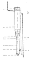
- Fig. 5 einen zum manuellen Drehen eines Rohrstranges mit seiner Kette das vordere Ende eines Rohres umschlingenden Kettenschlüssel; und
- Fig. 6 einen zum automatischen Drehen eines Rohrstranges mit einem Kettenschlüssel gemäß Fig. 5 verbundenen nachgreifenden Zylinder.
- Beim horizontalen Rammen gemäß Fig. 1 greift eine auf einem Lagerbock 1 geführte Ramme 2 mit ihrem Schlagkopf 3 über ein Zwischenstück 4 in das rückwärtige Ende eines auf einem als I-Träger 5 ausgebildeten Auflager geführten und am vorderen Ende mit einem Schneidschuh 6 versehenen Rohres 7 ein. Ein nicht dargestellter, im Inneren des Gehäuses 8 der Ramme 2 axial hin- und herbewegter Schlagkolben überträgt seine Schubkraft auf das Gehäuse 8 bzw. den Schlagkopf 3 sowie das Zwischenstück 4 und treibt mit jedem Hub das Rohr 7 weiter in das Erdreich hinein. Der Schlagkolben wird mittels Druckluft beaufschlagt, die von einem Kompressor 9 (vgl. Fig.2) über einen Druckmittelanschluß 10 mit integriertem Luftöler 11 (vgl. Fig. 2) in das Gehäuseinnere der Ramme 2 eingeleitet wird.
- Gegenüber der Anordnung gemäß Fig. 1 greift die Ramme bzw. das Rammbohrgerät 102 nicht in das rückwärtige Ende eines Rohres ein, sondern ist im Rohr angeordnet, wodurch sich eine kürzere Startgrube 13 als bei der Ausführung gemäß Fig. 1 erreichen läßt. In Fig. 2 ist das fast völlig in das Erdreich 14 eingerammte Rohr 7 (vgl. Fig. 1) sowie das Ansetzen eines neuen, d.h. Folgerohres 7′ dargestellt. Wie im einzelnen in Fig. 4 dargestellt, werden die Stirnflächen des Folgerohres 7′ und des noch mit einem Teilstück aus dem Erdreich 14 vorkragenden Rohres bzw. Rohrstranges 7 durch eine Schweißnaht 15 miteinander verbunden; zur Verstärkung der Schweißnaht 15 sind, beispielsweise an vier Stellen umfangsverteilt, Stahlbleche 16 mit Heftnähten 17 angeschweißt.
- Auf diese Weise werden so viele Rohre bzw. Rohrstöße 7, 7′, 7˝ angesetzt, wie nötig sind, um eine Rohrverbindung von der Startgrube 13 bis zu einer Zielgrube 18 herzustellen (vgl. Fig. 3). Jeweils zum Verschweißen eines neuen, d.h. eines sich dem bereits eingetriebenen Rohres 7 anschließenden Folgerohres 7′, 7˝ usw. wird das im Erdreich liegende Rohr 7 bzw. der bereits aus mehreren Rohrstößen bestehende Rohrstrang um seine Längsachse 19 entweder im Uhrzeigersinn oder entgegen dem Uhrzeigersinn gedreht. Während des Drehens wird das bereits im Erdreich 14 liegende Rohr 7 mit dem Folgerohr 7′ entlang der in Fig. 2 strichpunktiert dargestellten, umlaufenden Verbindungsstelle 20 verschweißt. Wie in Fig. 5 dargestellt ist, wird das im Erdreich liegende Rohr 7 manuell mittels eines Kettenschlüs sels 21 gedreht; die Kette 22 des Schlüssels 21 umschlingt das aus dem Erdreich vorkragende Ende des Rohres 7. Mit der Ausführung gemäß Fig. 6 ist ein automatisches Drehen des Rohres 7 möglich, und zwar ist in diesem Fall ein umsteuerbarer, nachgreifender Zylinder 23 mit seiner Kolbenstange 24 am Kettenschlüssel 21 befestigt. Unabhängig davon, ob die Rohre 7, 7′ usw. maschinell oder manuell miteinander verschweißt werden, läßt sich die umlaufende Schweißnaht 15 stets in einer günstigen, komplizierte Fall- und/oder Überkopfnähte vermeidenden Position anbringen.
Claims (4)
Applications Claiming Priority (2)
| Application Number | Priority Date | Filing Date | Title |
|---|---|---|---|
| DE3839633A DE3839633C1 (de) | 1988-11-24 | 1988-11-24 | |
| DE3839633 | 1988-11-24 |
Publications (3)
| Publication Number | Publication Date |
|---|---|
| EP0370183A2 true EP0370183A2 (de) | 1990-05-30 |
| EP0370183A3 EP0370183A3 (de) | 1991-02-06 |
| EP0370183B1 EP0370183B1 (de) | 1993-03-17 |
Family
ID=6367780
Family Applications (1)
| Application Number | Title | Priority Date | Filing Date |
|---|---|---|---|
| EP89115991A Expired - Lifetime EP0370183B1 (de) | 1988-11-24 | 1989-08-30 | Verfahren zum Verschweissen eines im Erdreich liegenden Rohrstranges mit einem Folgerohr |
Country Status (4)
| Country | Link |
|---|---|
| US (1) | US5013880A (de) |
| EP (1) | EP0370183B1 (de) |
| JP (1) | JPH02151369A (de) |
| DE (1) | DE3839633C1 (de) |
Cited By (1)
| Publication number | Priority date | Publication date | Assignee | Title |
|---|---|---|---|---|
| WO2022136802A1 (fr) | 2020-12-22 | 2022-06-30 | Saint-Gobain Glass France | Vitrage de toit pour vehicule automobile |
Families Citing this family (2)
| Publication number | Priority date | Publication date | Assignee | Title |
|---|---|---|---|---|
| NL1011069C2 (nl) * | 1999-01-19 | 2000-07-20 | Well Engineering Partners B V | Werkwijze en installatie voor het inbrengen van een buis in een boorgat in de aardbodem. |
| US8915675B1 (en) | 2009-11-23 | 2014-12-23 | Longshot Integrity Services, LLC | Access and connection for a buried pipeline |
Family Cites Families (9)
| Publication number | Priority date | Publication date | Assignee | Title |
|---|---|---|---|---|
| FR1084727A (fr) * | 1953-06-12 | 1955-01-24 | Dispositif tourne-virole | |
| US3461540A (en) * | 1966-05-23 | 1969-08-19 | Exxon Research Engineering Co | System for welding pipelines |
| US3800116A (en) * | 1970-12-29 | 1974-03-26 | Sumitomo Metal Ind | Apparatus for automatically welding pipe joints for cylindrical members such as steel pipe piles |
| US4081651A (en) * | 1976-05-06 | 1978-03-28 | Acf Industries, Incorporated | Apparatus method for welding tank sections |
| FR2509770A1 (fr) * | 1981-07-16 | 1983-01-21 | Inst Gornogo Dela Sibirskogo O | Procede de pose de conduites sans creusement de tranchees |
| GB8429287D0 (en) * | 1984-11-20 | 1984-12-27 | Alh Syst Ltd | Mole |
| DE3605961A1 (de) * | 1986-02-25 | 1987-08-27 | Gewerk Eisenhuette Westfalia | Pressrohr fuer den rohvorpressbetrieb sowie rohrvorpresseinrichtung |
| DE3642358A1 (de) * | 1986-12-11 | 1988-06-23 | Gewerk Eisenhuette Westfalia | Verfahren und einrichtungen zum verschweissen von rohren in rohrvorpressbetrieben |
| DE8707158U1 (de) * | 1987-05-19 | 1987-07-30 | Tracto-Technik Paul Schmidt Maschinenfabrik GmbH, 5940 Lennestadt | Rohrramme |
-
1988
- 1988-11-24 DE DE3839633A patent/DE3839633C1/de not_active Expired - Lifetime
-
1989
- 1989-08-30 EP EP89115991A patent/EP0370183B1/de not_active Expired - Lifetime
- 1989-09-27 JP JP1251700A patent/JPH02151369A/ja active Pending
- 1989-11-16 US US07/438,349 patent/US5013880A/en not_active Expired - Fee Related
Cited By (1)
| Publication number | Priority date | Publication date | Assignee | Title |
|---|---|---|---|---|
| WO2022136802A1 (fr) | 2020-12-22 | 2022-06-30 | Saint-Gobain Glass France | Vitrage de toit pour vehicule automobile |
Also Published As
| Publication number | Publication date |
|---|---|
| US5013880A (en) | 1991-05-07 |
| EP0370183A3 (de) | 1991-02-06 |
| JPH02151369A (ja) | 1990-06-11 |
| EP0370183B1 (de) | 1993-03-17 |
| DE3839633C1 (de) | 1990-04-05 |
Similar Documents
| Publication | Publication Date | Title |
|---|---|---|
| EP0565679B1 (de) | Verfahren insbesondere zum ersetzen von kanalisationsrohren sowie eine vorichtung zur durchführung des verfahrens | |
| EP2553202B1 (de) | Verfahren zum betrieb einer horizontalbohrvorrichtung und horizontalbohrvorrichtung | |
| WO2011120692A2 (de) | Verfahren zum erstellen einer horizontalbohrung im erdreich und horizontalbohrvorrichtung | |
| DE19817873C2 (de) | Verfahren und Vorrichtung zum grabenlosen Verlegen von Rohrleitungen im Erdreich | |
| EP0886714B1 (de) | Vorrichtung zur herstellung eines erdlochs | |
| EP0370183B1 (de) | Verfahren zum Verschweissen eines im Erdreich liegenden Rohrstranges mit einem Folgerohr | |
| WO2011120697A2 (de) | Horizontalbohrvorrichtung | |
| DE19511732C2 (de) | Verfahren zum Verlegen von Rohrleitungen im Erdreich zwischen Kontrollschächten | |
| DE102011000320A1 (de) | Bohranlage zum Durchführen von Bohrungen im Erdreich | |
| DE3903864C1 (en) | Method and apparatus for redeveloping old pipes | |
| DE3801824C1 (en) | Method and apparatus for the trenchless laying of supply lines | |
| EP2447462A1 (de) | Verfahren zum unterirdischen Einbringen einer Rohrleitung | |
| DE10011994C1 (de) | Seilzugvorrichtung für Berst-/Aufweitvorrichtungen | |
| DE3818998C3 (de) | Verfahren zum Verlegen von Versorgungsleitungen | |
| DE10159712B4 (de) | Bohrgerät und Verfahren zum Herstellen von Erdbohrungen | |
| EP1407112B1 (de) | Verfahren zum herstellen von erdbohrungen | |
| DE4116771C2 (de) | Vorrichtung zum Herstellen von Erdbohrungen | |
| DE19820483C1 (de) | Verfahren und Vorrichtung zur Erstellung gesteuerter Hausanschlüsse | |
| EP0418720B1 (de) | Verfahren zum Erneuern von Sickerwasserleitungen in Deponien sowie Einrichtung zum Durchführen des Verfahrens | |
| EP1361333B1 (de) | Erdbohrgerät | |
| EP0605364B1 (de) | Vorrichtung und Verfahren vorzugsweise zum Instandstellen eines Hausanschlussrohres | |
| DE3122710C2 (de) | Verfahren zum Verlegen von Rohren kleiner, nicht-begehbarer Innendurchmesser im Erdreich | |
| EP0748971A2 (de) | Verfahren und Vorrichtung zum grabenlosen Entfernen und Auswechseln erdverlegter Blei-und Kunststoffrohre | |
| DE2952593C2 (de) | Vorrichtung zum Einbringen von stangenförmigen Wärmetauschern in das Erdreich | |
| DE102017128404B4 (de) | Vorrichtung und Verfahren zur Inspektion und/oder Sanierung einer unterirdischen Rohrleitung |
Legal Events
| Date | Code | Title | Description |
|---|---|---|---|
| PUAI | Public reference made under article 153(3) epc to a published international application that has entered the european phase |
Free format text: ORIGINAL CODE: 0009012 |
|
| AK | Designated contracting states |
Kind code of ref document: A2 Designated state(s): BE CH FR GB IT LI NL |
|
| PUAL | Search report despatched |
Free format text: ORIGINAL CODE: 0009013 |
|
| AK | Designated contracting states |
Kind code of ref document: A3 Designated state(s): BE CH FR GB IT LI NL |
|
| 17P | Request for examination filed |
Effective date: 19910305 |
|
| 17Q | First examination report despatched |
Effective date: 19920716 |
|
| ITF | It: translation for a ep patent filed | ||
| GRAA | (expected) grant |
Free format text: ORIGINAL CODE: 0009210 |
|
| AK | Designated contracting states |
Kind code of ref document: B1 Designated state(s): BE CH FR GB IT LI NL |
|
| GBT | Gb: translation of ep patent filed (gb section 77(6)(a)/1977) |
Effective date: 19930406 |
|
| ET | Fr: translation filed | ||
| PG25 | Lapsed in a contracting state [announced via postgrant information from national office to epo] |
Ref country code: GB Effective date: 19930830 |
|
| PG25 | Lapsed in a contracting state [announced via postgrant information from national office to epo] |
Ref country code: LI Effective date: 19930831 Ref country code: CH Effective date: 19930831 Ref country code: BE Effective date: 19930831 |
|
| PLBE | No opposition filed within time limit |
Free format text: ORIGINAL CODE: 0009261 |
|
| STAA | Information on the status of an ep patent application or granted ep patent |
Free format text: STATUS: NO OPPOSITION FILED WITHIN TIME LIMIT |
|
| BERE | Be: lapsed |
Owner name: SCHMIDT PAUL Effective date: 19930831 |
|
| PG25 | Lapsed in a contracting state [announced via postgrant information from national office to epo] |
Ref country code: NL Effective date: 19940301 |
|
| 26N | No opposition filed | ||
| NLV4 | Nl: lapsed or anulled due to non-payment of the annual fee | ||
| GBPC | Gb: european patent ceased through non-payment of renewal fee |
Effective date: 19930830 |
|
| PG25 | Lapsed in a contracting state [announced via postgrant information from national office to epo] |
Ref country code: FR Effective date: 19940429 |
|
| REG | Reference to a national code |
Ref country code: CH Ref legal event code: PL |
|
| REG | Reference to a national code |
Ref country code: FR Ref legal event code: ST |
|
| PG25 | Lapsed in a contracting state [announced via postgrant information from national office to epo] |
Ref country code: IT Free format text: LAPSE BECAUSE OF NON-PAYMENT OF DUE FEES;WARNING: LAPSES OF ITALIAN PATENTS WITH EFFECTIVE DATE BEFORE 2007 MAY HAVE OCCURRED AT ANY TIME BEFORE 2007. THE CORRECT EFFECTIVE DATE MAY BE DIFFERENT FROM THE ONE RECORDED. Effective date: 20050830 |