EP0370188A1 - Dispositif de transport et enceinte à vide avec tel dispositif et procédé pour le chargement et le déchargement d'une enceinte de travail - Google Patents
Dispositif de transport et enceinte à vide avec tel dispositif et procédé pour le chargement et le déchargement d'une enceinte de travail Download PDFInfo
- Publication number
- EP0370188A1 EP0370188A1 EP89116747A EP89116747A EP0370188A1 EP 0370188 A1 EP0370188 A1 EP 0370188A1 EP 89116747 A EP89116747 A EP 89116747A EP 89116747 A EP89116747 A EP 89116747A EP 0370188 A1 EP0370188 A1 EP 0370188A1
- Authority
- EP
- European Patent Office
- Prior art keywords
- chamber
- lock
- transport
- transport device
- lever
- Prior art date
- Legal status (The legal status is an assumption and is not a legal conclusion. Google has not performed a legal analysis and makes no representation as to the accuracy of the status listed.)
- Granted
Links
Images


Classifications
-
- H—ELECTRICITY
- H10—SEMICONDUCTOR DEVICES; ELECTRIC SOLID-STATE DEVICES NOT OTHERWISE PROVIDED FOR
- H10P—GENERIC PROCESSES OR APPARATUS FOR THE MANUFACTURE OR TREATMENT OF DEVICES COVERED BY CLASS H10
- H10P72/00—Handling or holding of wafers, substrates or devices during manufacture or treatment thereof
- H10P72/04—Apparatus for manufacture or treatment
- H10P72/0451—Apparatus for manufacturing or treating in a plurality of work-stations
- H10P72/0466—Apparatus for manufacturing or treating in a plurality of work-stations characterised by the construction of the load-lock chamber
-
- C—CHEMISTRY; METALLURGY
- C23—COATING METALLIC MATERIAL; COATING MATERIAL WITH METALLIC MATERIAL; CHEMICAL SURFACE TREATMENT; DIFFUSION TREATMENT OF METALLIC MATERIAL; COATING BY VACUUM EVAPORATION, BY SPUTTERING, BY ION IMPLANTATION OR BY CHEMICAL VAPOUR DEPOSITION, IN GENERAL; INHIBITING CORROSION OF METALLIC MATERIAL OR INCRUSTATION IN GENERAL
- C23C—COATING METALLIC MATERIAL; COATING MATERIAL WITH METALLIC MATERIAL; SURFACE TREATMENT OF METALLIC MATERIAL BY DIFFUSION INTO THE SURFACE, BY CHEMICAL CONVERSION OR SUBSTITUTION; COATING BY VACUUM EVAPORATION, BY SPUTTERING, BY ION IMPLANTATION OR BY CHEMICAL VAPOUR DEPOSITION, IN GENERAL
- C23C14/00—Coating by vacuum evaporation, by sputtering or by ion implantation of the coating forming material
- C23C14/22—Coating by vacuum evaporation, by sputtering or by ion implantation of the coating forming material characterised by the process of coating
- C23C14/56—Apparatus specially adapted for continuous coating; Arrangements for maintaining the vacuum, e.g. vacuum locks
- C23C14/564—Means for minimising impurities in the coating chamber such as dust, moisture, residual gases
- C23C14/566—Means for minimising impurities in the coating chamber such as dust, moisture, residual gases using a load-lock chamber
-
- Y—GENERAL TAGGING OF NEW TECHNOLOGICAL DEVELOPMENTS; GENERAL TAGGING OF CROSS-SECTIONAL TECHNOLOGIES SPANNING OVER SEVERAL SECTIONS OF THE IPC; TECHNICAL SUBJECTS COVERED BY FORMER USPC CROSS-REFERENCE ART COLLECTIONS [XRACs] AND DIGESTS
- Y10—TECHNICAL SUBJECTS COVERED BY FORMER USPC
- Y10S—TECHNICAL SUBJECTS COVERED BY FORMER USPC CROSS-REFERENCE ART COLLECTIONS [XRACs] AND DIGESTS
- Y10S414/00—Material or article handling
- Y10S414/135—Associated with semiconductor wafer handling
- Y10S414/139—Associated with semiconductor wafer handling including wafer charging or discharging means for vacuum chamber
Definitions
- the present invention relates to a transport device for conveying a workpiece from a first environment into a second, essentially without one environment influencing the other. It further relates to a method for loading and emptying a processing chamber with a given processing atmosphere that differs from the chamber environment.
- the present invention also relates to a vacuum chamber with said transport device and to a use of the transport device or the vacuum chamber.
- a transport device is known from EP-A-0 242 997 for transferring workpieces from a workpiece magazine with a first environment into a treatment chamber, such as a vacuum chamber, with a second environment, from there into a third environment, etc.
- the transport device from one chamber to the other comprises a two-armed lever which is arranged between the above-mentioned chambers and can be folded into both.
- This lever is integrated in a sealing valve arrangement, with the aid of which the chambers can be sealingly separated from one another or connected to one another.
- This sealing valve arrangement is designed like a gate, so that either the two chambers concerned and thus their atmospheres are connected or separated from one another.
- Such a transport device has the disadvantage that each time the lever is swung into one of the two chambers concerned, the two chambers mentioned are connected, which results in a compensation of the respective atmospheres. If you have to work in one of the chambers with a working atmosphere kept within narrow tolerances, this procedure means that after each transport operation that affects the two chambers mentioned, the chamber mentioned must be reconditioned.
- the transport device shown here is not able to convey a workpiece from a first environment into a second one without intermediate storage, essentially without one environment influencing the other.
- a special transfer cycle is described below, from one prechamber into the vacuum chamber and into the next prechamber, with all three chambers being connected to one another, with which relatively large volumes, namely those of the intermediate chambers, influence the vacuum chamber.
- a transport device consisting of a lock chamber, in which a two-armed pivot lever is mounted essentially centrally in the chamber and can be extended on both sides from conventional slot valves.
- the two arms of the transport lever are driven separately, which enables the control of a practically any curved path of the end receiving part of the lever.
- this transport device is disadvantageous in the sense that the drive and the corresponding bushings for the two lever arms are vacuum-tight are extraordinarily complicated and that the chamber is relatively voluminous, which has a negative effect on the pump units or output and times to be installed.
- EP-OS 0 291 690 In addition, reference is made to EP-OS 0 291 690.
- the aim of the present invention is to create a transport device of the type mentioned at the outset, in which only minimal volumes have to be conditioned, after a transport operation from one environment to the other, which significantly reduces the cycle time, and furthermore has the task of this Optimize cycle time through a targeted transport rhythm.
- the invention is distinguished on the one hand by the wording of claim 1, on the other hand by the wording of claim 12.
- the volume of the lock chamber must be considered: While in the first case the cycle time and the evacuation and conditioning units to be provided depend to a large extent on the lock chamber volume, which is to be evacuated and conditioned, in the second case the lock chamber volume also influences the measure which the conditions in the treatment chamber are influenced by the volume trapped in the lock chamber.
- the lock chamber has lock gates on both sides of the pivot bearing for the lever, such that the lever with its part facing away from the pivot bearing leaves the chamber with the lock gate open in each case can be swung out, it is achieved that for a given lock chamber extension, the greatest possible swivel path can be traversed with this lever, which, viewed in reverse, achieves a minimum lock chamber volume for a given swivel path.
- the transport device comprises a lever pivoted in the lock chamber, m.a.W. given the possibility of limiting the chamber volume by the azimuthal extension of the lever with respect to the pivot bearing and, on the other hand, of giving the transport path to be covered by the transport device through the radial extension of the lever. As mentioned, this results in the possibility of designing the chamber volume largely independently of the transport route to be traversed.
- the lock gates viewed in the direction of the pivot bearing axis, are preferably arranged such that they border a surface that is essentially given by the shape of the lever and a workpiece to be conveyed that is brought into the lock chamber. This limits this area to the minimum required size.
- lock gates be formed by slot valves, preferably MONOVAT valves from V.A.T.
- valves of this type therefore have very significant advantages with regard to service life and in particular with regard to minimizing abrasion compared to "two-way slit valves".
- the valves used according to the invention are also described, for example, in DE-OS 38 01 998.
- a vacuum chamber with a transport device designed as mentioned is proposed.
- Such a vacuum chamber is particularly suitable for the coating of memory discs in which the vacuum chamber of metals, such as e.g. of aluminum or aluminum alloys.
- the handling of the supplied discs becomes workpieces and the loading devices to be provided are particularly simple and inexpensive by in particular for the chamber feeds, the discs can be handed over to the respective transport lever in a freely accessible location.
- the concept proposed according to the invention allows, especially in the production of memory discs, that without reducing the cycle times, only one or two workpieces, e.g. CD's, are introduced into the vacuum treatment process by the takeover point, so that the system can be stopped at any time if the overall process malfunctions, without a large number of discs being involved in the vacuum coating process and would have to be eliminated as a scrap when the system was restarted or would have to be waited until many workpieces that were already involved in the treatment process when the system stopped had left the vacuum treatment process, ie the vacuum chamber, in order to restart the overall process.
- workpieces e.g. CD's
- the workpiece is not only to be understood as a one-piece part, but rather a unit which is conveyed together with one of the respective levers and which can consist of several individual parts to be treated simultaneously.
- FIG. 1 schematically shows a lock chamber 1 according to the invention. It comprises a tight border 3, on which two lock gates 5a and 5b are provided in a manner to be described later.
- the lock gate 5a separates the inside of the lock chamber 1 with the volume V1 from its one environment U7, which prevails in a treatment chamber 7 that is only partially entered.
- the treatment chamber 7 can in particular be a vacuum treatment chamber.
- the second lock gate 5b separates the inside of the lock chamber 1 from its second environment U0, for example the outside environment of the treatment chamber 7.
- a lever 11 is arranged, pivotably mounted about an axis 9, as a transport device, which according to FIG. 1 , as one of the many possible exemplary embodiments, is designed in the shape of a sector of a circle.
- the lever 11 By pivoting about the axis 9, the lever 11 sweeps a dashed circle at K 11, around a workpiece 13, which is preferably transported to the end of the lever 11 deposited at the pivot axis 9, back and forth between the environment U7 and the environment U0 promote.
- the lock gates 5a or 5b are dimensioned longer or shorter.
- the inner volume V 1 of the lock chamber must be evacuated and conditioned if the environment U 0 is to be prevented from influencing the environment U 7. If it is also to be prevented, for example because of the toxicity of the environment U7, that the environment U7 influences the environment U0 in the reverse cycle, then the lock chamber 1, with the internal volume V1, when the workpiece 13 is introduced into U7, then returning the lever 11 to the environment U0, evacuated twice.
- the aim is to keep the necessary volume V 1 of the lock chamber 1 as minimal as possible and still be able to control the required positions in the two environments U0 and U7.
- the lock volume V 1 is given on the one hand by the outline shown, in addition to, of course, its height.
- the outline contour is measured according to the maximum azimuthal extension ⁇ o of the lever 11 or of the workpiece 13 when the latter projects beyond the lever 11.
- the possible transport is dependent on the radial length 1 o of the lever 11, whereby the volume of the sluice chamber 1 can be largely designed independently of the to be passed through the conveying path by minimization of ⁇ o at the required length 1 o.
- the lever 11 is in turn pivotally mounted in a lock chamber 1a so as to be pivotable about the axis 9, the floor plan of the chamber 1a is also formed in a sector of a circle by the two lock gates 5a and 5b essentially be arranged according to the shape of the lever 11, thus here essentially parallel to the legs of the circular sector. If, as shown in dashed lines at 13a, workpieces have to be transported from the environment U0 to the environment U7 or vice versa, which exceed the azimuthal extension of the lever 11, the shape of the lock chamber 1a must of course take this into account, as shown at 5a '.
- FIG 3 shows a lock chamber arrangement with two lock chambers 20 and 22 according to the invention.
- the respective walls 21 and 23 of the lock chambers have lock gates 21a, 21b or 22a and 22b, so that the two lock gates 21a and 22a seal the interior of the lock chambers 20 and 22 in a sealed manner against the environment U0, the lock gates 21b and 22b against the environment U7 within the treatment chamber 7.
- Both lock chambers 20, 22 in turn have a lever 29 or 30 which can be rotated about a respective axis 25 or 27 as the transport device.
- the respective lock gates are also di dimensioned.
- the lever 29 can be used to convey a workpiece from a pick-up position P 2 in the vicinity U 1 to the treatment position P 1 in the treatment chamber 7 and, after appropriate treatment, can be picked up by the lever 30 and promoted into the removal position P3 in the area U mental.
- the two positions P2 and P3 can be in two different environments and accordingly lock chambers 20 and 22 separate three different environments, so that the workpiece from P2 in one environment to P1 in the second, then to P3 in a third environment is promoted.
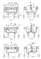
- FIG. 4a-f show a vacuum chamber according to the invention with a lock chamber arrangement according to the invention, for applying the reflection layer to the plastic base body of compact discs, as workpieces, in the vacuum chamber mentioned as a treatment chamber.
- Two lock chambers 32a and 32b according to the invention are provided on a vacuum chamber 31. Both chambers 32 each have a pair of lock gates 34a, 34b and 35a, 35b.
- lock gates 34, 35, as well as lock gates in the exemplary embodiments described above are preferred So-called slit valves, such as those manufactured and sold under the name MONOVAT by VAT, are used.
- the vacuum chamber environment U31 is partitioned off from the outside environment U0.
- a spoon-shaped transport lever 36a or 36b is pivotably mounted on corresponding axes of rotation 38a or 38b, the pivot axes 38 being arranged adjacent to one another.
- Each of the two lock chambers 32 has an evacuation valve 40a or 40b and a valve 42a or 42b guided against the environment. The lines assigned to the evacuation valves 40 each lead to vacuum sources 44a and 44b.
- an argon tank 46 is provided in the vacuum chamber 31 for the vacuum deposition process considered here and is connected to the vacuum chamber 31 via a controllable valve 48.
- a vacuum source 52 is connected to it via a valve 50.
- FIG. 4a shows the starting position of the chamber 31.
- the lock chamber 32a is closed on both sides with the slit valves 35a and 35b.
- the slit valve 34a of the chamber 32b is also closed, the slit valve 34b is open or closed sen, shown in Fig. 4a closed.
- the vacuum chamber 31 is evacuated and conditioned via the valve 48 from the argon tank 46 to the required argon atmosphere.
- the right lock chamber 32a is evacuated via the evacuation valve 40a.
- the two still empty transport levers 36 lie within the lock chambers 32.
- the lever 36b is then pivoted back into its lock chamber 32b, at the same time the lever 36a into its lock chamber 32a, after which all slot valves 35a, b and 34a, b are closed.
- the vacuum source 44b after opening the valve 40b, the left lock chamber 32b is evacuated, at the same time, by opening the valve 42a, the right lock chamber 32a is placed at ambient pressure corresponding to U0.
- the slit valve 34a is opened, as is the configuration in FIG. 4d Slit valve 35b, and on the one hand the transport lever 36b loaded with the still uncoated disc 54 is pivoted into the vacuum chamber 31, and on the other hand the still unloaded transport lever 36a is pivoted into the surroundings U0.
- the receiving part of the spoon-shaped lever 36a assumes the same receiving position that had previously assumed the receiving part of the spoon-shaped transport lever 36b according to FIG. 4b.
- the still uncoated disc 54 is treated in the vacuum chamber 31, for example by aluminum alloy vacuum deposition, as schematically represented by A.
- a further uncoated disc 54a is placed on the transport lever 36a by means of a loading apparatus which is not of interest in connection with the present invention. Thereafter, the two transport levers 36 pivot back into the position shown in Fig. 4e.
- the lever 36b carries the coated disc 54, while the lever 36a carries the disc 54a still to be treated.
- the treatment positions for the discs to be coated, such as CD's, in the vacuum chamber 31 are also the same for both transport levers 36, as the cross-comparison mentioned shows.
- the disc coating process continues cyclically, i.e. during the coating of the disc 54a, the lever 36b receives a disc to be coated, etc.
- FIGS. 4b to 4f only the reference numerals given in their description have been used, the rest result from the illustration in FIG. 4a.
- the argon atmosphere in the vacuum chamber 31 is kept constant, and it is readily apparent that, according to the invention, both lock chambers 32 are dimensioned to a minimum volume, so that the respective evacuations with the vacuum sources 44a and 44b ( Fig. 4a) can be carried out with the least possible effort and in the shortest possible times and there are only minimal changes in the atmosphere U31 he give when an evacuated lock chamber 32 is opened to chamber 31.
- FIG. 5 again in top view and schematically, shows a lock chamber arrangement according to the invention in analogy to that shown in FIG. 4.
- the same position numbers as used in Fig. 4 are used.
Landscapes
- Chemical & Material Sciences (AREA)
- Chemical Kinetics & Catalysis (AREA)
- Engineering & Computer Science (AREA)
- Materials Engineering (AREA)
- Mechanical Engineering (AREA)
- Metallurgy (AREA)
- Organic Chemistry (AREA)
- Physical Vapour Deposition (AREA)
- Vacuum Packaging (AREA)
- Feeding Of Workpieces (AREA)
- Manufacturing Optical Record Carriers (AREA)
- Container, Conveyance, Adherence, Positioning, Of Wafer (AREA)
Applications Claiming Priority (2)
| Application Number | Priority Date | Filing Date | Title |
|---|---|---|---|
| CH426788 | 1988-11-17 | ||
| CH4267/88 | 1988-11-17 |
Publications (2)
| Publication Number | Publication Date |
|---|---|
| EP0370188A1 true EP0370188A1 (fr) | 1990-05-30 |
| EP0370188B1 EP0370188B1 (fr) | 1998-07-15 |
Family
ID=4272920
Family Applications (1)
| Application Number | Title | Priority Date | Filing Date |
|---|---|---|---|
| EP89116747A Expired - Lifetime EP0370188B1 (fr) | 1988-11-17 | 1989-09-11 | Dispositif de transport et enceinte à vide avec un tel dispositif et procédé pour le chargement et le déchargement d'une enceinte de travail |
Country Status (5)
| Country | Link |
|---|---|
| US (1) | US5017073A (fr) |
| EP (1) | EP0370188B1 (fr) |
| JP (1) | JPH02213469A (fr) |
| AT (1) | ATE168501T1 (fr) |
| DE (1) | DE58909835D1 (fr) |
Cited By (2)
| Publication number | Priority date | Publication date | Assignee | Title |
|---|---|---|---|---|
| EP0555764A1 (fr) * | 1992-02-12 | 1993-08-18 | Balzers Aktiengesellschaft | Appareillage de traitement sous vide |
| DE4427984A1 (de) * | 1994-08-08 | 1996-02-15 | Leybold Ag | Vorrichtung zum Ein- und Ausschleusen von Werkstücken in eine Beschichtungskammer |
Families Citing this family (3)
| Publication number | Priority date | Publication date | Assignee | Title |
|---|---|---|---|---|
| US5400317A (en) * | 1993-04-01 | 1995-03-21 | Balzers Aktiengesellschaft | Method of coating a workpiece of a plastic material by a metal layer |
| JP2014035315A (ja) * | 2012-08-10 | 2014-02-24 | Hitachi High-Technologies Corp | ディスク搬送ユニット及び検査装置 |
| EP2909684B1 (fr) * | 2012-10-22 | 2020-04-22 | Güdel Group AG | Procédé et agencement permettant de générer et tester des trajectoires de transport d'une pièce dans une presse multiposte |
Citations (6)
| Publication number | Priority date | Publication date | Assignee | Title |
|---|---|---|---|---|
| GB2143494A (en) * | 1981-02-13 | 1985-02-13 | Lam Res Corp | Improvements in or relating to workpiece transfer means for loadlocks |
| US4553069A (en) * | 1984-01-05 | 1985-11-12 | General Ionex Corporation | Wafer holding apparatus for ion implantation |
| US4670126A (en) * | 1986-04-28 | 1987-06-02 | Varian Associates, Inc. | Sputter module for modular wafer processing system |
| EP0242997A2 (fr) * | 1986-04-17 | 1987-10-28 | Varian Associates, Inc. | Valve dans laquelle est incorporé un bras de transport de plaquettes |
| EP0246798A2 (fr) * | 1986-05-19 | 1987-11-25 | Machine Technology Inc. | Dispositif modulaire de traitement pour traiter des plaquettes semi-conductrices |
| DE3801998C1 (fr) * | 1988-01-23 | 1989-05-18 | Schertler, Siegfried, Haag, Ch |
Family Cites Families (10)
| Publication number | Priority date | Publication date | Assignee | Title |
|---|---|---|---|---|
| US4584045A (en) * | 1984-02-21 | 1986-04-22 | Plasma-Therm, Inc. | Apparatus for conveying a semiconductor wafer |
| US4534314A (en) * | 1984-05-10 | 1985-08-13 | Varian Associates, Inc. | Load lock pumping mechanism |
| US4733746A (en) * | 1985-06-17 | 1988-03-29 | Honda Giken Kogyo Kabushiki Kaisha | Vacuum treating method and apparatus |
| US4746256A (en) * | 1986-03-13 | 1988-05-24 | Roboptek, Inc. | Apparatus for handling sensitive material such as semiconductor wafers |
| US4705951A (en) * | 1986-04-17 | 1987-11-10 | Varian Associates, Inc. | Wafer processing system |
| US4715764A (en) * | 1986-04-28 | 1987-12-29 | Varian Associates, Inc. | Gate valve for wafer processing system |
| US4917556A (en) * | 1986-04-28 | 1990-04-17 | Varian Associates, Inc. | Modular wafer transport and processing system |
| US4861563A (en) * | 1987-05-14 | 1989-08-29 | Spectrum Cvd, Inc. | Vacuum load lock |
| US4828224A (en) * | 1987-10-15 | 1989-05-09 | Epsilon Technology, Inc. | Chemical vapor deposition system |
| US4857160A (en) * | 1988-07-25 | 1989-08-15 | Oerlikon-Buhrle U.S.A. Inc. | High vacuum processing system and method |
-
1989
- 1989-09-11 EP EP89116747A patent/EP0370188B1/fr not_active Expired - Lifetime
- 1989-09-11 DE DE58909835T patent/DE58909835D1/de not_active Expired - Fee Related
- 1989-09-11 AT AT89116747T patent/ATE168501T1/de not_active IP Right Cessation
- 1989-11-09 US US07/434,417 patent/US5017073A/en not_active Expired - Fee Related
- 1989-11-13 JP JP1292523A patent/JPH02213469A/ja active Pending
Patent Citations (6)
| Publication number | Priority date | Publication date | Assignee | Title |
|---|---|---|---|---|
| GB2143494A (en) * | 1981-02-13 | 1985-02-13 | Lam Res Corp | Improvements in or relating to workpiece transfer means for loadlocks |
| US4553069A (en) * | 1984-01-05 | 1985-11-12 | General Ionex Corporation | Wafer holding apparatus for ion implantation |
| EP0242997A2 (fr) * | 1986-04-17 | 1987-10-28 | Varian Associates, Inc. | Valve dans laquelle est incorporé un bras de transport de plaquettes |
| US4670126A (en) * | 1986-04-28 | 1987-06-02 | Varian Associates, Inc. | Sputter module for modular wafer processing system |
| EP0246798A2 (fr) * | 1986-05-19 | 1987-11-25 | Machine Technology Inc. | Dispositif modulaire de traitement pour traiter des plaquettes semi-conductrices |
| DE3801998C1 (fr) * | 1988-01-23 | 1989-05-18 | Schertler, Siegfried, Haag, Ch |
Cited By (3)
| Publication number | Priority date | Publication date | Assignee | Title |
|---|---|---|---|---|
| EP0555764A1 (fr) * | 1992-02-12 | 1993-08-18 | Balzers Aktiengesellschaft | Appareillage de traitement sous vide |
| DE4427984A1 (de) * | 1994-08-08 | 1996-02-15 | Leybold Ag | Vorrichtung zum Ein- und Ausschleusen von Werkstücken in eine Beschichtungskammer |
| DE4427984C2 (de) * | 1994-08-08 | 2003-07-03 | Unaxis Deutschland Holding | Vorrichtung zum Ein- und Ausschleusen von Werkstücken in eine Beschichtungskammer |
Also Published As
| Publication number | Publication date |
|---|---|
| JPH02213469A (ja) | 1990-08-24 |
| DE58909835D1 (de) | 1998-08-20 |
| US5017073A (en) | 1991-05-21 |
| ATE168501T1 (de) | 1998-08-15 |
| EP0370188B1 (fr) | 1998-07-15 |
Similar Documents
| Publication | Publication Date | Title |
|---|---|---|
| EP0591706B1 (fr) | Enceinte pour le transport des substrats | |
| DE69937483T2 (de) | Vakuumvorrichtung | |
| CH691376A5 (de) | Vakuumanlage zur Oberflächenbearbeitung von Werkstücken. | |
| DE3783440T2 (de) | Modulare foerder- und beabeitungsanlage fuer halbleiterwafer. | |
| EP0354294B1 (fr) | Appareillage de type carrousel pour le revêtement de substrats | |
| DE69128612T2 (de) | Ladegerät mit Ansaughaltemechanismus | |
| DE69208937T2 (de) | Halbleiter-Herstellungseinrichtung | |
| EP3730257B1 (fr) | Robot de préparation de commandes muni d'un effecteur terminal pourvu de préhenseurs à ventouse pouvant être activés par la rotation | |
| DE69307445T2 (de) | Schichtbildende Vorrichtung | |
| DE3204312A1 (de) | Einschleusvorrichtung | |
| EP0853657A1 (fr) | Dispositif de stockage d'objets, station de stockage et armoire de climatisation | |
| DE4009603A1 (de) | Vorrichtung zum ein- und ausschleusen eines werkstuecks in eine vakuumkammer | |
| DE3915038A1 (de) | Halte- und transportvorrichtung fuer eine scheibe | |
| EP0905275B1 (fr) | Dispositif pour revêtir un substrat essentiellement plat en forme de disque | |
| DE69112922T2 (de) | Anlage mit einer Vakuumkammer. | |
| DE69905274T2 (de) | Vorrichtung zur in-line behandlung von gegenständen in einem künstlichen medium | |
| EP0370188B1 (fr) | Dispositif de transport et enceinte à vide avec un tel dispositif et procédé pour le chargement et le déchargement d'une enceinte de travail | |
| DE69637404T2 (de) | Ladearm für ladungsverschluss | |
| DE4235676A1 (de) | Kammer und Kammerkombination für eine Vakuumanlage und Verfahren zum Durchreichen mindestens eines Werkstückes | |
| DE10319379A1 (de) | Vorrichtung zum Transportieren eines flachen Substrats in einer Vakuumkammer | |
| DE3317574A1 (de) | Werkstueck-sammel- und transportvorrichtung | |
| DE4408947A1 (de) | Vakuumbehandlungsanlage und Ventilanordnung | |
| DE4235677C2 (de) | Vakuumkammer, Vakuumbehandlungsanlage mit einer solchen Kammer sowie Transportverfahren | |
| EP0609489B1 (fr) | Dispositif pour appliquer un masque sur un substrat et/ou pour l'enlever | |
| CH691377A5 (de) | Kammeranordnung für den Transport von Werkstücken und deren Verwendung. |
Legal Events
| Date | Code | Title | Description |
|---|---|---|---|
| PUAI | Public reference made under article 153(3) epc to a published international application that has entered the european phase |
Free format text: ORIGINAL CODE: 0009012 |
|
| AK | Designated contracting states |
Kind code of ref document: A1 Designated state(s): AT BE CH DE ES FR GB GR IT LI LU NL SE |
|
| 17P | Request for examination filed |
Effective date: 19900705 |
|
| 17Q | First examination report despatched |
Effective date: 19931214 |
|
| GRAG | Despatch of communication of intention to grant |
Free format text: ORIGINAL CODE: EPIDOS AGRA |
|
| GRAG | Despatch of communication of intention to grant |
Free format text: ORIGINAL CODE: EPIDOS AGRA |
|
| GRAH | Despatch of communication of intention to grant a patent |
Free format text: ORIGINAL CODE: EPIDOS IGRA |
|
| GRAH | Despatch of communication of intention to grant a patent |
Free format text: ORIGINAL CODE: EPIDOS IGRA |
|
| GRAA | (expected) grant |
Free format text: ORIGINAL CODE: 0009210 |
|
| AK | Designated contracting states |
Kind code of ref document: B1 Designated state(s): AT BE CH DE ES FR GB GR IT LI LU NL SE |
|
| PG25 | Lapsed in a contracting state [announced via postgrant information from national office to epo] |
Ref country code: IT Free format text: LAPSE BECAUSE OF FAILURE TO SUBMIT A TRANSLATION OF THE DESCRIPTION OR TO PAY THE FEE WITHIN THE PRE;WARNING: LAPSES OF ITALIAN PATENTS WITH EFFECTIVE DATE BEFORE 2007 MAY HAVE OCCURRED AT ANY TIME BEFORE 2007. THE CORRECT EFFECTIVE DATE MAY BE DIFFERENT FROM THE ONE RECORDED.SCRIBED TIME-LIMIT Effective date: 19980715 Ref country code: NL Free format text: LAPSE BECAUSE OF FAILURE TO SUBMIT A TRANSLATION OF THE DESCRIPTION OR TO PAY THE FEE WITHIN THE PRESCRIBED TIME-LIMIT Effective date: 19980715 Ref country code: FR Free format text: LAPSE BECAUSE OF FAILURE TO SUBMIT A TRANSLATION OF THE DESCRIPTION OR TO PAY THE FEE WITHIN THE PRESCRIBED TIME-LIMIT Effective date: 19980715 Ref country code: GR Free format text: LAPSE BECAUSE OF FAILURE TO SUBMIT A TRANSLATION OF THE DESCRIPTION OR TO PAY THE FEE WITHIN THE PRESCRIBED TIME-LIMIT Effective date: 19980715 Ref country code: GB Free format text: LAPSE BECAUSE OF FAILURE TO SUBMIT A TRANSLATION OF THE DESCRIPTION OR TO PAY THE FEE WITHIN THE PRESCRIBED TIME-LIMIT Effective date: 19980715 Ref country code: ES Free format text: THE PATENT HAS BEEN ANNULLED BY A DECISION OF A NATIONAL AUTHORITY Effective date: 19980715 |
|
| REF | Corresponds to: |
Ref document number: 168501 Country of ref document: AT Date of ref document: 19980815 Kind code of ref document: T |
|
| REG | Reference to a national code |
Ref country code: CH Ref legal event code: EP |
|
| REF | Corresponds to: |
Ref document number: 58909835 Country of ref document: DE Date of ref document: 19980820 |
|
| PG25 | Lapsed in a contracting state [announced via postgrant information from national office to epo] |
Ref country code: LU Free format text: LAPSE BECAUSE OF NON-PAYMENT OF DUE FEES Effective date: 19980911 |
|
| PG25 | Lapsed in a contracting state [announced via postgrant information from national office to epo] |
Ref country code: BE Free format text: LAPSE BECAUSE OF NON-PAYMENT OF DUE FEES Effective date: 19980930 |
|
| PG25 | Lapsed in a contracting state [announced via postgrant information from national office to epo] |
Ref country code: SE Free format text: LAPSE BECAUSE OF FAILURE TO SUBMIT A TRANSLATION OF THE DESCRIPTION OR TO PAY THE FEE WITHIN THE PRESCRIBED TIME-LIMIT Effective date: 19981015 |
|
| NLV1 | Nl: lapsed or annulled due to failure to fulfill the requirements of art. 29p and 29m of the patents act | ||
| EN | Fr: translation not filed | ||
| GBV | Gb: ep patent (uk) treated as always having been void in accordance with gb section 77(7)/1977 [no translation filed] |
Effective date: 19980715 |
|
| BERE | Be: lapsed |
Owner name: BALZERS A.G. Effective date: 19980930 |
|
| PLBE | No opposition filed within time limit |
Free format text: ORIGINAL CODE: 0009261 |
|
| STAA | Information on the status of an ep patent application or granted ep patent |
Free format text: STATUS: NO OPPOSITION FILED WITHIN TIME LIMIT |
|
| 26N | No opposition filed | ||
| PGFP | Annual fee paid to national office [announced via postgrant information from national office to epo] |
Ref country code: DE Payment date: 20000904 Year of fee payment: 12 |
|
| PGFP | Annual fee paid to national office [announced via postgrant information from national office to epo] |
Ref country code: AT Payment date: 20000913 Year of fee payment: 12 |
|
| PGFP | Annual fee paid to national office [announced via postgrant information from national office to epo] |
Ref country code: CH Payment date: 20001215 Year of fee payment: 12 |
|
| PG25 | Lapsed in a contracting state [announced via postgrant information from national office to epo] |
Ref country code: AT Free format text: LAPSE BECAUSE OF NON-PAYMENT OF DUE FEES Effective date: 20010911 |
|
| PG25 | Lapsed in a contracting state [announced via postgrant information from national office to epo] |
Ref country code: LI Free format text: LAPSE BECAUSE OF NON-PAYMENT OF DUE FEES Effective date: 20010930 Ref country code: CH Free format text: LAPSE BECAUSE OF NON-PAYMENT OF DUE FEES Effective date: 20010930 |
|
| PG25 | Lapsed in a contracting state [announced via postgrant information from national office to epo] |
Ref country code: DE Free format text: LAPSE BECAUSE OF NON-PAYMENT OF DUE FEES Effective date: 20020501 |
|
| REG | Reference to a national code |
Ref country code: CH Ref legal event code: PL |