EP0370197B1 - Ski, versehen mit seitwärts gelegener Trägheitsmasse - Google Patents
Ski, versehen mit seitwärts gelegener Trägheitsmasse Download PDFInfo
- Publication number
- EP0370197B1 EP0370197B1 EP89117608A EP89117608A EP0370197B1 EP 0370197 B1 EP0370197 B1 EP 0370197B1 EP 89117608 A EP89117608 A EP 89117608A EP 89117608 A EP89117608 A EP 89117608A EP 0370197 B1 EP0370197 B1 EP 0370197B1
- Authority
- EP
- European Patent Office
- Prior art keywords
- ski
- inertia
- additional
- vicinity
- masses
- Prior art date
- Legal status (The legal status is an assumption and is not a legal conclusion. Google has not performed a legal analysis and makes no representation as to the accuracy of the status listed.)
- Expired - Lifetime
Links
- 230000000694 effects Effects 0.000 description 4
- 238000005452 bending Methods 0.000 description 3
- 230000027455 binding Effects 0.000 description 2
- 238000009739 binding Methods 0.000 description 2
- 230000001413 cellular effect Effects 0.000 description 2
- 210000003850 cellular structure Anatomy 0.000 description 2
- 238000010276 construction Methods 0.000 description 2
- 238000013016 damping Methods 0.000 description 2
- 238000006073 displacement reaction Methods 0.000 description 2
- 230000005484 gravity Effects 0.000 description 2
- 239000000463 material Substances 0.000 description 2
- 229910001369 Brass Inorganic materials 0.000 description 1
- 229910052782 aluminium Inorganic materials 0.000 description 1
- XAGFODPZIPBFFR-UHFFFAOYSA-N aluminium Chemical compound [Al] XAGFODPZIPBFFR-UHFFFAOYSA-N 0.000 description 1
- 239000010951 brass Substances 0.000 description 1
- 210000003855 cell nucleus Anatomy 0.000 description 1
- 239000002131 composite material Substances 0.000 description 1
- 230000007547 defect Effects 0.000 description 1
- 238000009826 distribution Methods 0.000 description 1
- 230000005284 excitation Effects 0.000 description 1
- 239000011888 foil Substances 0.000 description 1
- 239000011133 lead Substances 0.000 description 1
- 238000003754 machining Methods 0.000 description 1
- 238000004519 manufacturing process Methods 0.000 description 1
- 229910052751 metal Inorganic materials 0.000 description 1
- 239000002184 metal Substances 0.000 description 1
- 238000000034 method Methods 0.000 description 1
- 238000003801 milling Methods 0.000 description 1
- 230000035945 sensitivity Effects 0.000 description 1
- 239000012815 thermoplastic material Substances 0.000 description 1
- WFKWXMTUELFFGS-UHFFFAOYSA-N tungsten Chemical compound [W] WFKWXMTUELFFGS-UHFFFAOYSA-N 0.000 description 1
- 229910052721 tungsten Inorganic materials 0.000 description 1
- 239000010937 tungsten Substances 0.000 description 1
Images



Classifications
-
- A—HUMAN NECESSITIES
- A63—SPORTS; GAMES; AMUSEMENTS
- A63C—SKATES; SKIS; ROLLER SKATES; DESIGN OR LAYOUT OF COURTS, RINKS OR THE LIKE
- A63C5/00—Skis or snowboards
- A63C5/06—Skis or snowboards with special devices thereon, e.g. steering devices
- A63C5/075—Vibration dampers
Definitions
- the present invention relates to skis in which one or more additional masses of inertia make it possible to modify and adjust the moment of inertia of the ski both around a vertical axis, around a horizontal axis perpendicular to the direction longitudinal of the ski, and around the longitudinal axis of the ski.
- the moment of inertia around the vertical axis, or axis of rotation of the ski influences the behavior of the ski in rotation, by determining the resistance that the ski opposes to a variation in the direction of movement.
- a ski with a low moment of inertia for example a short ski or a light ski at its ends, is easier to turn than a ski with a high moment of inertia.
- An easy to turn ski is particularly suitable for special snow conditions such as deep snow, spring snow, and for special terrain conditions such as bumpy slopes.
- a ski with a high moment of inertia for example an elongated ski or a ski having relatively large masses at its ends, is particularly stable in direction during a rapid descent, because the forces exerted laterally on the ski by the Track unevenness is better absorbed due to the higher moment of inertia.
- a ski is known in which, to modify its moment of inertia, masses centered on the longitudinal axis of the ski can be moved in the direction of its length and immobilized on or inside its posterior part or earlier.
- By modifying the distance of the masses at the two ends of a ski one can vary its moment of inertia both around the vertical axis and around the central horizontal axis perpendicular to its longitudinal direction.
- the practical implementation of this system is however very difficult and costly.
- the arrangement of the masses outside the ski cannot be used in practice, by the fact that snow can accumulate in the adjustment members and prevent their operation.
- the French document FR-A-2 382 245 teaches to have additional masses of interie in the longitudinal axis of the ski on the upper surface of the ski, at the two ends of the ski. This document does not include any teaching on the positioning of interior masses in the particular zones which provide an appropriate effect as will be described below.
- the German document DE-A-1 960 684 teaches to have on the ski surface one or more damping strips made up of a viscoelastic layer and a stress layer, like an aluminum foil.
- the bands which are preferably arranged on either side of the longitudinal axis of the ski and extend in an area located between the bindings and the front contact point of the ski.
- a ski is not only subjected to bending and pivoting forces, but also to torsional forces and excitations.
- the present invention results from the observation that it is possible to modify appreciably and advantageously the natural modes of torsional vibration and the damping of the ski by placing additional masses of inertia no longer in the longitudinal axis of the ski, but distributed by on either side near the edges of the ski. This results in a significant improvement in the handling of the ski in the curves, and in the length of attachment of the ski to the snow. It is understood that the provision of additional masses of inertia in the vicinity of the edges of the ski increases the moment of inertia of the ski around its longitudinal axis.
- the precision and regularity of driving a turn is significantly improved, not less sensitivity of the ski to the terrain of the piste; directional stability is significantly improved to make it similar to that of heavy skis, without however increasing the total weight of the ski and keeping it at a value substantially lower than that of heavy skis.
- the ski can be easily oriented at low speed of movement or rotation, while its relatively high moment of inertia around its longitudinal axis absorbs the rapid stresses imparted by the reliefs of the track during turns. This results in less physical and psychological fatigue for the skier.
- the ski according to the present invention defined in claim 1 comprises a light structure, with a cell nucleus, and is provided with at least one element of density greater than the average density of structure of the body ski and constituting an additional mass of inertia distributed on either side of the vertical plane passing through one of the transverse contact lines of the ski; according to the invention, said additional mass of inertia is distributed off-center on either side of the vertical longitudinal median plane of the ski, so as to constitute an assembly equivalent to two weights offset respectively on either side of the plane vertical longitudinal median of the ski, said assembly having an appropriate moment of inertia with respect to the longitudinal axis of the ski.
- the additional mass of inertia is a plate of non-uniform thickness, the thickness being small in the vicinity of the longitudinal axis of the ski and being greater in the vicinity of the edges of the ski.
- the additional mass of inertia is a plate of non-uniform length, the plate length being shorter in the vicinity of the longitudinal axis of the ski and being greater in the vicinity of the edges of the ski.
- This characteristic of non-uniform length can moreover be combined with the characteristic of non-uniform thickness mentioned above.
- the additional mass of inertia comprises two separate lateral half-masses disposed respectively on either side of the longitudinal axis of the ski in the vicinity of the edges of the ski.
- the additional masses of inertia can be placed on the upper surface of the ski.
- the additional inertia masses are incorporated in the internal structure of the ski.
- the lateral portions of additional inertia masses can be advantageously incorporated into the lateral portions of the ski on either side of the central cellular core.
- the ski comprises inclined lateral edges, the inclination being such that the width of the ski is greater in the vicinity of its base than in the vicinity of its upper face, the lateral portions of inertia masses additional are shaped to follow the inclination of the edges, so that the center of gravity of the ski is thus lowered.
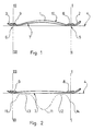
- the ski according to the present invention comprises, in a traditional manner, a ski body 1 the central part of which is curved, curved in an upward arc and the two ends of which are raised upwards, the front end forming a spatula 2, the rear end 3 also being raised upwards.
- the bending of the central part of the body 1 causes the ski to rest on the plane 4 along two transverse lines, a transverse front contact line 5, a transverse rear contact line 6.
- the ski When in use, the ski is intended to rest on the ground according to its lower contact surface 7, which surface is limited by the two lines 5 and 6.
- An additional front inertia mass 8 is placed in the vicinity of the front transverse contact line 5.
- An additional rear inertia mass 9 is placed in the vicinity of the rear transverse contact line 6.
- the additional masses of inertia 8 and 9 are fixed on the upper surface 10 of the ski.
- the additional inertia masses 8 and 9 are fixed and incorporated in the body of the ski, being non-visible or only partially visible on the upper surface 10 of the ski.
- a ski according to the present invention provided with its two additional masses of inertia 8 and 9, placed on a flat surface 4, and subjected to a load such as the weight of a user.
- a load such as the weight of a user.
- the lower contact surface 7 of the ski is entirely in contact with the plane 4.
- the contact pressure between the lower ski surface 7 and the plane 4 varies as a function of the longitudinal position considered along the ski.
- This pressure has a maximum 11 under the central zone occupied by the bindings and receiving the weight of the skier.
- This pressure then has a minimum on either side of the maximum 11, namely a minimum 12 in the front third of the ski and a minimum 13 in the rear third.
- the pressure has a relative maximum 14 in the vicinity of the front transverse contact line 5 of the ski and a second relative maximum 15 in the vicinity of the rear transverse contact line 6 of the ski. It can therefore be seen that, when the additional inertia masses 8 and 9 are positioned in the vicinity of the front contact lines 5 and rear 6 of the ski, their position corresponds to a relative maximum of contact pressure below the surface of the ski.
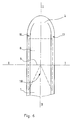
- the additional front mass of inertia 8 is in one piece, and is distributed in a non-uniform manner on either side of the median longitudinal axis II - II of the ski. It may for example be a plate with a density greater than the average density of the ski body 1.
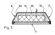
- the additional mass of inertia 8 extends to the vicinity of the edges 16 and 17 of the ski.
- the additional mass of inertia 8 comprises a central zone 85 connecting a first lateral zone 86 arranged in the vicinity of the edge 16 of the ski and a second lateral zone 87 arranged in the vicinity of the second edge 17 of the ski.
- the central zone 85 has a relatively small thickness E in comparison with the thickness of the lateral zones 86 and 87.
- the central zone 85 is arranged above the central core 19 with cellular structure of the ski.
- the central zone 85 of the additional mass of inertia can be arranged below the central core 19.
- the ski comprises lateral edges 16 and 17 inclined.
- the lateral portions 86 and 87 of additional inertia masses are advantageously shaped to follow the inclination of the edges. In this case, it can advantageously have a greater width in the vicinity of the lower sliding surface 7 of the ski than in the vicinity of the upper surface 10 of the ski. In this way, the presence of the additional inertia masses lowers the center of gravity of the ski, that is to say, brings it closer to the lower sliding surface 7.
- the zones lateral 86 and 87 of the additional inertia mass 8 have a triangular section and occupy all the available section between the lateral edges 16 and 17 and the lateral faces of the central core 19.
- the additional front mass of inertia 8 is a plate comprising a central cutout 18 in V, so that the mass 8 is distributed in a privileged manner in the vicinity of the edges 16 and 17 of the ski .
- the length of the plate forming the additional mass of inertia before 8 is not uniform, this length being shorter in the vicinity of the longitudinal axis II - II of the ski and being greater in the vicinity of the edges 16 and 17 of the ski.
- This embodiment can be combined with the previous characteristic according to which the thickness of the plate forming the additional front mass of inertia 8 of the ski is smaller in the vicinity of the longitudinal axis II - II of the ski and greater in the vicinity side edges 16 and 17 of the ski.
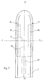
- FIG. 7 and 8 there is shown an embodiment in which the additional mass of inertia before 8 of the ski consists of two half-masses 81 and 82, the first half-mass 81 being arranged along the edge 16 ski, the second half-mass 82 being disposed along the ski edge 17.
- the ski according to the invention advantageously has a cellular structure, with a central core 19 of constant width. The core 19 is thus bordered, over part of its length, by the half-masses 81 and 82, as shown in FIG. 8.
- the half-masses 81 and 82 are advantageously shaped to follow the inclined shape of the edges.
- lateral inertia masses can be distributed in the vicinity of the front contact line 5.
- the two lateral half-masses 81 and 82 are shown, similar to the half-masses of the modes of previous embodiments, but associated with two additional lateral auxiliary masses 83 and 84 arranged slightly behind the additional masses 81 and 82.
- FIG. 10 shows an embodiment in which the rear additional inertia mass 9 consists of two lateral half inertia masses 91 and 92 disposed respectively in the vicinity of the edges 16 and 17 of the ski.
- the additional mass of inertia before 8 is distributed on either side of the vertical plane I - I passing through the transverse line of contact before 5 along a certain length, of the order of 15 to 25 centimeters.
- the distance L1 between the anterior end of the additional mass of inertia 8 and the vertical plane I - I passing through the front transverse contact line 5 is advantageously between 0 and 10 centimeters; similarly, the length L2 between the rear end of the additional mass of inertia 8 and the vertical plane I - I passing through the front transverse contact line 5 is advantageously between 0 and 15 centimeters.
- ski For the types of ski corresponding to a preferred type of evolution, for example a slalom ski, a giant slalom ski, a downhill ski, or a multi-purpose ski, it is possible to approximately adapt the behavior of the ski by adjusting the value of the additional inertia masses 8 and 9.
- the additional front mass of inertia 8 has a value greater than the rear additional mass of inertia 9, the difference between the two masses possibly being of the order of 50 grams.
- the additional masses may consist of lead plates or other heavy materials. They can be placed in housings provided for this purpose.
- the housing of the additional masses can be carried out by any conventional machining means such as milling, routing, either in the central part 19 forming the core, or in the lateral parts called edges.
- the additional inertia masses can be partially housed in housings provided in the core 19 and partially housed in the side edges of the ski.
- additional inertia masses can be a composite material, combining the forming and adhesion qualities of a thermoplastic material with the density qualities of a metal such as lead, brass, tungsten.
Landscapes
- Golf Clubs (AREA)
- Fittings On The Vehicle Exterior For Carrying Loads, And Devices For Holding Or Mounting Articles (AREA)
- Transition And Organic Metals Composition Catalysts For Addition Polymerization (AREA)
- Turbine Rotor Nozzle Sealing (AREA)
Claims (11)
- Ski mit leichtem Aufbau, welcher mit mindestens einem Element (8) versehen ist, das eine zusätzliche Trägheitsmasse (8) bildet, welche in dezentralisierter Weise beiderseits der mittleren vertikalen Längsebene (II-II) des Ski verteilt ist, derart, daß eine äquivalente Gesamtheit mit zwei jeweils beiderseits der mittleren vertikalen Längsebene (II-II) des Ski verschobenen Reguliergewichten gebildet wird, dadurch gekennzeichnet, daß
das Element (8, 9) eine größere Dichte als die mittlere Dichte des Aufbaus des Skikörpers (1) aufweist und daß die Masse des Elementes (8, 9) auf eine bestimmte Länge beiderseits der vertikalen Ebene (I-I; III-III), welche durch eine der Querkontaktlinien (5, 6) des Ski verläuft, verteilt ist. - Ski nach Anspruch 1, dadurch gekennzeichnet, daß er eine zusätzliche vordere Trägheitsmasse (8) aufweist, welche in der Nähe der vorderen Querkontaktlinie (5) des Ski angeordnet ist, und eine zusätzliche hintere Trägheitsmasse (9), welche in der Nähe der hinteren Querkontaktlinie (6) des Ski angeordnet ist.
- Ski nach Anspruch 1, dadurch gekennzeichnet, daß die zusätzliche Trägheitsmasse (8) eine Platte nicht einheitlicher Dicke ist, wobei die Dicke (E) im mittleren Teil (85) in der Nähe der Längsachse (II-II) des Ski klein und in den seitlichen Teilen (86, 87) in der Nähe der seitlichen Kanten (16, 17) des Ski größer ist.
- Ski nach einem der Ansprüche 1 bis 3, dadurch gekennzeichnet, daß die zusätzliche Trägheitsmasse (8) eine Platte nicht einheitlicher Länge ist, wobei die Länge in der Nähe der Längsachse (II-II) des Ski kleiner und in der Nähe der seitlichen Kanten (16, 17) größer ist.
- Ski nach Anspruch 1, dadurch gekennzeichnet, daß die zusätzliche Trägheitsmasse (8) zwei seitliche Halbmassen (81, 82) aufweist, welche jeweils beiderseits der Längsachse (II-II) des Ski der Nähe der seitlichen Kanten (16, 17) des Ski angeordnet sind.
- Ski nach einem der Ansprüche 1 bis 5, dadurch gekennzeichnet, daß die zusätzlichen Träheitsmassen (8, 9) auf der Oberseite des Ski befestigt sind.
- Ski nach einem der Ansprüche 1 bis 5, dadurch gekennzeichnet, daß die zusätzlichen Trägheitsmassen (8, 9) im inneren Aufbau des Ski einverleibt sind.
- Ski nach Anspruch 7, dadurch gekennzeichnet, daß die seitlichen Teile (86, 87) der zusätzlichen Trägheitsmassen (8) in den seitlichen Skiabschnitten beiderseits des zentralen Kerns (19) einverleibt sind.
- Ski nach Anspruch 8, dadurch gekennzeichnet dadurch, daß er seitliche geneigte Kanten (16, 17) aufweist, und daß die seitlichen Teile (86, 87) der zusätzlichen Trägheitsmassen derart geformt sind, daß sie der Neigung der Kanten folgen.
- Ski nach Anspruch 9, dadurch gekennzeichnet, daß die seitlichen Teile (86, 87) der zusätzlichen Trägheitsmassen in der Nähe der unteren Gleitoberfläche (7) eine größere Breite aufweisen als in der Nähe der Oberseite (10) des Ski.
- Ski nach Anspruch 10, dadurch gekennzeichnet, daß die seitlichen Teile (86, 87) der zusätzlichen Trägheitsmassen einen dreieckförmigen Querschnitt aufweisen.
Priority Applications (1)
| Application Number | Priority Date | Filing Date | Title |
|---|---|---|---|
| AT89117608T ATE86873T1 (de) | 1988-11-07 | 1989-09-23 | Ski, versehen mit seitwaerts gelegener traegheitsmasse. |
Applications Claiming Priority (2)
| Application Number | Priority Date | Filing Date | Title |
|---|---|---|---|
| FR8815725 | 1988-11-07 | ||
| FR8815725A FR2638649B1 (fr) | 1988-11-07 | 1988-11-07 | Ski muni de masses d'inertie laterales |
Publications (2)
| Publication Number | Publication Date |
|---|---|
| EP0370197A1 EP0370197A1 (de) | 1990-05-30 |
| EP0370197B1 true EP0370197B1 (de) | 1993-03-17 |
Family
ID=9372463
Family Applications (1)
| Application Number | Title | Priority Date | Filing Date |
|---|---|---|---|
| EP89117608A Expired - Lifetime EP0370197B1 (de) | 1988-11-07 | 1989-09-23 | Ski, versehen mit seitwärts gelegener Trägheitsmasse |
Country Status (5)
| Country | Link |
|---|---|
| EP (1) | EP0370197B1 (de) |
| JP (1) | JPH0736843B2 (de) |
| AT (1) | ATE86873T1 (de) |
| DE (1) | DE68905440T2 (de) |
| FR (1) | FR2638649B1 (de) |
Families Citing this family (5)
| Publication number | Priority date | Publication date | Assignee | Title |
|---|---|---|---|---|
| US5096217A (en) * | 1988-12-01 | 1992-03-17 | Kent Hunter | Monoski with deep side cuts and cambered segment in the binding portion |
| AT400676B (de) * | 1991-02-22 | 1996-02-26 | Head Sport Ag | Ski |
| FR2716117B1 (fr) * | 1994-02-17 | 1997-06-06 | Rossignol Sa | Procédé pour la fabrication d'un ski à noyau et ski ainsi obtenu. |
| FR2951955A1 (fr) * | 2009-11-03 | 2011-05-06 | Alain Nicolas Calmet | Masselottes aimantees pour le ski de randonnee |
| AT512157B1 (de) * | 2012-03-27 | 2013-06-15 | Fischer Sports Gmbh | Vorrichtung zur Aufnahme einer Skibindung |
Family Cites Families (5)
| Publication number | Priority date | Publication date | Assignee | Title |
|---|---|---|---|---|
| US3537717A (en) * | 1968-11-29 | 1970-11-03 | Minnesota Mining & Mfg | Damped ski and method of making |
| AT337581B (de) * | 1974-11-25 | 1977-07-11 | Werner Konradler Amann | Langgestreckter gleitkorper mit aufgebogenem vorderen ende, insbesondere schi |
| FR2503570A2 (fr) * | 1980-02-21 | 1982-10-15 | Rossignol Sa | Ski |
| ATE37293T1 (de) * | 1982-06-11 | 1988-10-15 | Dynastar Skis Sa | Mit einer schwingungsdaempfungsvorrichtung ausgeruesteter ski. |
| FR2615406B1 (fr) * | 1987-05-22 | 1989-07-21 | Salomon Sa | Ski a amortissement reparti |
-
1988
- 1988-11-07 FR FR8815725A patent/FR2638649B1/fr not_active Expired - Fee Related
-
1989
- 1989-09-23 EP EP89117608A patent/EP0370197B1/de not_active Expired - Lifetime
- 1989-09-23 AT AT89117608T patent/ATE86873T1/de not_active IP Right Cessation
- 1989-09-23 DE DE89117608T patent/DE68905440T2/de not_active Expired - Fee Related
- 1989-11-07 JP JP1288074A patent/JPH0736843B2/ja not_active Expired - Lifetime
Also Published As
| Publication number | Publication date |
|---|---|
| ATE86873T1 (de) | 1993-04-15 |
| DE68905440D1 (de) | 1993-04-22 |
| JPH0736843B2 (ja) | 1995-04-26 |
| JPH02177980A (ja) | 1990-07-11 |
| EP0370197A1 (de) | 1990-05-30 |
| FR2638649B1 (fr) | 1991-01-11 |
| FR2638649A1 (fr) | 1990-05-11 |
| DE68905440T2 (de) | 1994-03-10 |
Similar Documents
| Publication | Publication Date | Title |
|---|---|---|
| EP0622096B1 (de) | Snowboard | |
| EP0465794B1 (de) | Ski mit gerippter Oberfläche | |
| EP0409749B1 (de) | Zusatzvorrichtung zum Ski zur Montage eines Paares Skibindungen auf dem Ski | |
| EP0567780B1 (de) | Ski mit Auflageplatte | |
| WO2001054777A1 (fr) | Planche de glisse destinee a la pratique du surf sur neige | |
| EP0188985A1 (de) | Ski | |
| EP0617638B1 (de) | Einrichtung zur druckverteilung eines schis auf der gleitläche | |
| EP0498053A1 (de) | Ski für Wintersport mit Montagebühne für Skibindungen | |
| EP1383584A1 (de) | Rahmen mit kontrolierter verformung für ein gleitgerät, insbesondere einem rollbrett | |
| EP0439713B1 (de) | Langlaufski zum Gleiten | |
| EP0370197A1 (de) | Ski, versehen mit seitwärts gelegener Trägheitsmasse | |
| EP0367964B1 (de) | Ski mit einem Schwingungsdämpfer auf dem Vorderteil | |
| EP0826397A1 (de) | Schneegleitbrett mit einer Dämpfungseinrichtung | |
| EP0850094A1 (de) | Einsprurrollschuhe | |
| FR2639242A1 (fr) | Ensemble perfectionne pour la pratique du ski, constitue par une chaussure et un ski | |
| FR2787723A1 (fr) | Planche de glisse | |
| EP1430935B1 (de) | Alpinski | |
| EP1011818A1 (de) | Mit oszillierenden vibrationsdäpfungselementen ausgestatteter tennisschläger | |
| EP0732966B1 (de) | Unterstützungsplatte für skistiefel | |
| EP0753330B1 (de) | Übungsmittel zum Erlernen des Skilanglaufs nach der Schlittschuhlaufschritttechnik | |
| FR2675700A1 (fr) | Ski, en particulier ski alpin. | |
| FR2670392A1 (fr) | Ski pour sport d'hiver constitue d'une embase et d'un raidisseur. | |
| EP4091683B1 (de) | Kern für gleitbrett und entsprechendes gleitbrett | |
| FR2798073A1 (fr) | Ski alpin prevu pour etre equipe d'un dispositif interface et ensemble a skier | |
| FR2674443A1 (fr) | Ski a face superieure nervuree. |
Legal Events
| Date | Code | Title | Description |
|---|---|---|---|
| PUAI | Public reference made under article 153(3) epc to a published international application that has entered the european phase |
Free format text: ORIGINAL CODE: 0009012 |
|
| AK | Designated contracting states |
Kind code of ref document: A1 Designated state(s): AT CH DE IT LI SE |
|
| 17P | Request for examination filed |
Effective date: 19900511 |
|
| 17Q | First examination report despatched |
Effective date: 19910725 |
|
| GRAA | (expected) grant |
Free format text: ORIGINAL CODE: 0009210 |
|
| AK | Designated contracting states |
Kind code of ref document: B1 Designated state(s): AT CH DE IT LI SE |
|
| PG25 | Lapsed in a contracting state [announced via postgrant information from national office to epo] |
Ref country code: IT Free format text: LAPSE BECAUSE OF FAILURE TO SUBMIT A TRANSLATION OF THE DESCRIPTION OR TO PAY THE FEE WITHIN THE PRESCRIBED TIME-LIMIT;WARNING: LAPSES OF ITALIAN PATENTS WITH EFFECTIVE DATE BEFORE 2007 MAY HAVE OCCURRED AT ANY TIME BEFORE 2007. THE CORRECT EFFECTIVE DATE MAY BE DIFFERENT FROM THE ONE RECORDED. Effective date: 19930317 Ref country code: SE Effective date: 19930317 |
|
| REF | Corresponds to: |
Ref document number: 86873 Country of ref document: AT Date of ref document: 19930415 Kind code of ref document: T |
|
| REF | Corresponds to: |
Ref document number: 68905440 Country of ref document: DE Date of ref document: 19930422 |
|
| PG25 | Lapsed in a contracting state [announced via postgrant information from national office to epo] |
Ref country code: CH Effective date: 19930930 Ref country code: LI Effective date: 19930930 |
|
| PLBE | No opposition filed within time limit |
Free format text: ORIGINAL CODE: 0009261 |
|
| STAA | Information on the status of an ep patent application or granted ep patent |
Free format text: STATUS: NO OPPOSITION FILED WITHIN TIME LIMIT |
|
| 26N | No opposition filed | ||
| REG | Reference to a national code |
Ref country code: CH Ref legal event code: PL |
|
| PGFP | Annual fee paid to national office [announced via postgrant information from national office to epo] |
Ref country code: DE Payment date: 19971027 Year of fee payment: 9 |
|
| PG25 | Lapsed in a contracting state [announced via postgrant information from national office to epo] |
Ref country code: DE Free format text: LAPSE BECAUSE OF NON-PAYMENT OF DUE FEES Effective date: 19990701 |
|
| PGFP | Annual fee paid to national office [announced via postgrant information from national office to epo] |
Ref country code: AT Payment date: 20050913 Year of fee payment: 17 |
|
| PG25 | Lapsed in a contracting state [announced via postgrant information from national office to epo] |
Ref country code: AT Free format text: LAPSE BECAUSE OF NON-PAYMENT OF DUE FEES Effective date: 20060923 |