EP0370221A1 - Verfahren zur Begrenzung der Abflussmenge aus einem Flüssigkeitsbehälter - Google Patents
Verfahren zur Begrenzung der Abflussmenge aus einem Flüssigkeitsbehälter Download PDFInfo
- Publication number
- EP0370221A1 EP0370221A1 EP89118927A EP89118927A EP0370221A1 EP 0370221 A1 EP0370221 A1 EP 0370221A1 EP 89118927 A EP89118927 A EP 89118927A EP 89118927 A EP89118927 A EP 89118927A EP 0370221 A1 EP0370221 A1 EP 0370221A1
- Authority
- EP
- European Patent Office
- Prior art keywords
- drain
- liquids
- container
- centrifugal pump
- counterflow
- Prior art date
- Legal status (The legal status is an assumption and is not a legal conclusion. Google has not performed a legal analysis and makes no representation as to the accuracy of the status listed.)
- Granted
Links
- 238000000034 method Methods 0.000 title claims abstract description 10
- 239000007788 liquid Substances 0.000 title claims abstract description 8
- 239000002351 wastewater Substances 0.000 claims description 9
- 230000001105 regulatory effect Effects 0.000 claims description 2
- 238000004140 cleaning Methods 0.000 description 2
- 230000000694 effects Effects 0.000 description 1
- 230000008030 elimination Effects 0.000 description 1
- 238000003379 elimination reaction Methods 0.000 description 1
- 230000014759 maintenance of location Effects 0.000 description 1
- 239000010865 sewage Substances 0.000 description 1
- 239000007787 solid Substances 0.000 description 1
- 230000003068 static effect Effects 0.000 description 1
- 238000011144 upstream manufacturing Methods 0.000 description 1
- XLYOFNOQVPJJNP-UHFFFAOYSA-N water Substances O XLYOFNOQVPJJNP-UHFFFAOYSA-N 0.000 description 1
Images
Classifications
-
- E—FIXED CONSTRUCTIONS
- E03—WATER SUPPLY; SEWERAGE
- E03F—SEWERS; CESSPOOLS
- E03F5/00—Sewerage structures
- E03F5/10—Collecting-tanks; Equalising-tanks for regulating the run-off; Laying-up basins
- E03F5/105—Accessories, e.g. flow regulators or cleaning devices
-
- E—FIXED CONSTRUCTIONS
- E03—WATER SUPPLY; SEWERAGE
- E03F—SEWERS; CESSPOOLS
- E03F5/00—Sewerage structures
- E03F5/10—Collecting-tanks; Equalising-tanks for regulating the run-off; Laying-up basins
- E03F5/105—Accessories, e.g. flow regulators or cleaning devices
- E03F5/107—Active flow control devices, i.e. moving during flow regulation
-
- G—PHYSICS
- G05—CONTROLLING; REGULATING
- G05D—SYSTEMS FOR CONTROLLING OR REGULATING NON-ELECTRIC VARIABLES
- G05D7/00—Control of flow
- G05D7/06—Control of flow characterised by the use of electric means
- G05D7/0617—Control of flow characterised by the use of electric means specially adapted for fluid materials
- G05D7/0629—Control of flow characterised by the use of electric means specially adapted for fluid materials characterised by the type of regulator means
- G05D7/0676—Control of flow characterised by the use of electric means specially adapted for fluid materials characterised by the type of regulator means by action on flow sources
Definitions
- the invention relates to a method and devices for limiting the amount of liquid flowing out of a liquid container via a drain, in particular for throttling the amount of drain from a waste water basin.
- the invention is particularly applicable to rain overflow basins, storage channels and rain retention basins.
- the throttling devices used up to now to control the flow rate such as balance throttle, vortex throttle, hydroslide or electromotive controlled slide valves, operate unreliably in the lower volume range of approximately 5 to 30 l / s, since the reduction in volume is caused by a considerable change in the cross-section of the drain channel. Because of the admixtures contained in the wastewater, clogging or failure of the control system is very easy. The elimination of the source of interference, usually a solid part, is very complex and often only possible when the pool is empty.
- the invention has for its object to provide a method and devices for its implementation, with the help of a constant flow rate limitation without narrowing the cross-section of the drain is possible.
- the object is achieved in that a counterflow is generated in the drain. This is conveniently done by a centrifugal pump.
- the drain line of the basin is thus led to the pump pressure side, so that the tank inlet pressure can be adjusted by the delivery pressure of the centrifugal pump so that a continuous flow rate is achieved via the pump suction side.
- the basic idea of the invention is to achieve a reduction in the upstream pressure by means of hydraulic friction. A cross-sectional narrowing is thus avoided.
- a counter-current system following this method can be operated at a constant speed. The flow rate achieved is almost constant. In systems with high control accuracy or with variable discharge quantities, speed control of the counterflow pump is recommended.
- the invention is explained in more detail using an exemplary embodiment.
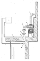
- the drawing shows the drainage area of a rain overflow basin in a schematic representation.
- the speed of the electric motor (7) driving the wastewater centrifugal pump (5) depends on the level measured by a pressure sensor (8) in the rain overflow basin (1) with the aid of a static frequency converter and a controller which are arranged in a housing (9) regulated.
- the admission pressure of the rain overflow basin (1) is thus set by the delivery pressure generated by the wastewater centrifugal pump (5) in such a way that a discharge quantity of high control accuracy results at the suction nozzle (6).
Landscapes
- Engineering & Computer Science (AREA)
- Health & Medical Sciences (AREA)
- Life Sciences & Earth Sciences (AREA)
- Hydrology & Water Resources (AREA)
- Public Health (AREA)
- Water Supply & Treatment (AREA)
- Physics & Mathematics (AREA)
- General Physics & Mathematics (AREA)
- Automation & Control Theory (AREA)
- Control Of Non-Positive-Displacement Pumps (AREA)
- Structures Of Non-Positive Displacement Pumps (AREA)
- Electrical Discharge Machining, Electrochemical Machining, And Combined Machining (AREA)
- Control Of Positive-Displacement Pumps (AREA)
- External Artificial Organs (AREA)
Abstract
Description
- Die Erfindung betrifft ein Verfahren und Einrichtungen zur Begrenzung der einem Flüssigkeitsbehälter über einen Abfluß entströmenden Flüssigkeitsmenge, insbesondere zur Drosselung der Abflußmenge aus einem Abwasserbecken. Die Erfindung ist vor allem auch bei Regenüberlaufbecken, Stauraumkanälen und Regenrückhaltebecken anwendbar.
- Die Notwendigkeit der Abflußmengenregelung ergibt sich bei den oben als Beispiel genannten Anwendungsfällen aus dem Umstand, daß die biologische Reinigungswirkung einer Kläranlage nur bei bestimmten Mengen zufließenden Abwassers gewährleistet ist. Große Mengendifferenzen können zu erheblichen Problemen, im Extremfall sogar zum Ausfall der biologischen Reinigung führen. Es ist daher Bedingung, daß unabhängig vom Füllstand im Becken eine konstante Abwassermenge abgeführt wird.
- Die bis dato zur Abflußmengenregelung eingesetzten Drosseleinrichtungen, wie Waagedrossel, Wirbeldrossel, Hydroslide oder elektromotorisch betriebene geregelte Schieber arbeiten im unteren Mengenbereich von etwa 5 bis 30 l/s unzuverlässig, da die Mengenreduktion durch eine erhebliche Querschnittsveränderung des Abflußkanals bewirkt wird. Wegen der im Abwasser enthaltenen Beimengungen kommt es hier sehr leicht zu Verstopfungen oder zu einem Ausfall der Steuerung. Die Beseitigung der Störquelle, meist ein Feststoffteil, ist sehr aufwendig und vielfach erst bei entleertem Becken möglich.
- Der Erfindung liegt die Aufgabe zugrunde, ein Verfahren und Einrichtungen zu seiner Durchführung zu schaffen, mit deren Hilfe eine konstante Abflußmengenbegrenzung ohne Querschnittsverengung des Abflusses möglich ist.
- Die gestellte Aufgabe wird erfindungsgemäß dadurch gelöst, daß in dem Abfluß eine Gegenströmung erzeugt wird. Dies geschieht in zweckmäßiger Weise durch eine Kreiselpumpe. Die Abflußleitung des Beckens wird also zur Pumpendruckseite geführt, so daß der Beckenvordruck durch den Förderdruck der Kreiselpumpe so einzustellen ist, daß über die Pumpensaugseite eine kontinuierliche Abflußmenge erreicht wird. Der Grundgedanke der Erfindung liegt darin, eine Reduzierung des Vordrucks durch hydraulische Reibung zu erreichen. Eine Querschnittsverengung wird somit vermieden. Im Normalfall kann eine diesem Verfahren folgende Gegenstromanlage mit konstanter Drehzahl betrieben werden. Die dabei erzielte Abflußmenge ist nahezu konstant. Bei Anlagen mit hoher Regelgenauigkeit bzw. bei variablen Abflußmengen ist eine Drehzahlsteuerung der Gegenstrompumpe zu empfehlen.
- Anhand eines Ausführungsbeispiels wird die Erfindung näher erläutert. Die Zeichnung zeigt den Abflußbereich eines Regenüberlaufbeckens in schematischer Darstellung.
- Im Regenüberlaufbecken (1) wird Regenwasser bis zu einer Höhe von etwa 6 m gespeichert. In die vom Abfluß (2) des Regenüberlaufbeckens (1) ausgehende Abflußleitung (3) mündet die Druckleitung (4) einer Abwasserkreiselpumpe (5). Über die Saugleitung (6) der Abwasserkreiselpumpe (5) fließt das aus dem Regenüberlaufbecken (1) kommende Wasser schließlich ab.
- Der die Abwasserkreiselpumpe (5) antreibende Elektromotor (7) wird in Abhängigkeit der von einem Druckaufnehmer (8) im Regenüberlaufbecken (1) gemessenen Füllstandshöhe mit Hilfe eines statischen Frequenzumformers und eines Reglers, die in einem Gehäuse (9) angeordnet sind, in seiner Drehzahl geregelt. Der Vordruck des Regenüberlaufbeckens (1) wird somit durch den von der Abwasserkreiselpumpe (5) erzeugten Förderdruck so eingestellt, daß sich am Saugstutzen (6) eine Abflußmenge hoher Regelgenauigkeit ergibt.
Claims (5)
Priority Applications (1)
| Application Number | Priority Date | Filing Date | Title |
|---|---|---|---|
| AT89118927T ATE89938T1 (de) | 1988-10-22 | 1989-10-12 | Verfahren zur begrenzung der abflussmenge aus einem fluessigkeitsbehaelter. |
Applications Claiming Priority (2)
| Application Number | Priority Date | Filing Date | Title |
|---|---|---|---|
| DE3836065 | 1988-10-22 | ||
| DE3836065A DE3836065A1 (de) | 1988-10-22 | 1988-10-22 | Verfahren zur begrenzung der abflussmenge aus einem fluessigkeitsbehaelter |
Publications (2)
| Publication Number | Publication Date |
|---|---|
| EP0370221A1 true EP0370221A1 (de) | 1990-05-30 |
| EP0370221B1 EP0370221B1 (de) | 1993-05-26 |
Family
ID=6365718
Family Applications (1)
| Application Number | Title | Priority Date | Filing Date |
|---|---|---|---|
| EP89118927A Expired - Lifetime EP0370221B1 (de) | 1988-10-22 | 1989-10-12 | Verfahren zur Begrenzung der Abflussmenge aus einem Flüssigkeitsbehälter |
Country Status (3)
| Country | Link |
|---|---|
| EP (1) | EP0370221B1 (de) |
| AT (1) | ATE89938T1 (de) |
| DE (2) | DE3836065A1 (de) |
Cited By (1)
| Publication number | Priority date | Publication date | Assignee | Title |
|---|---|---|---|---|
| CN111395487A (zh) * | 2019-10-18 | 2020-07-10 | 浙江一体环保科技有限公司 | 一种智能雨水回收利用系统 |
Citations (1)
| Publication number | Priority date | Publication date | Assignee | Title |
|---|---|---|---|---|
| DE3617284A1 (de) * | 1985-05-25 | 1986-11-27 | Oskar Vollmar GmbH, 7000 Stuttgart | Verfahren und anlage zur regelung des wasserabflusses aus einem regenbecken oder einem kanalrohr |
-
1988
- 1988-10-22 DE DE3836065A patent/DE3836065A1/de not_active Withdrawn
-
1989
- 1989-10-12 AT AT89118927T patent/ATE89938T1/de not_active IP Right Cessation
- 1989-10-12 DE DE8989118927T patent/DE58904492D1/de not_active Expired - Fee Related
- 1989-10-12 EP EP89118927A patent/EP0370221B1/de not_active Expired - Lifetime
Patent Citations (1)
| Publication number | Priority date | Publication date | Assignee | Title |
|---|---|---|---|---|
| DE3617284A1 (de) * | 1985-05-25 | 1986-11-27 | Oskar Vollmar GmbH, 7000 Stuttgart | Verfahren und anlage zur regelung des wasserabflusses aus einem regenbecken oder einem kanalrohr |
Non-Patent Citations (2)
| Title |
|---|
| PATENT ABSTRACTS OF JAPAN * |
| REGELUNGSTECHNISCHE PRAXIS * |
Cited By (1)
| Publication number | Priority date | Publication date | Assignee | Title |
|---|---|---|---|---|
| CN111395487A (zh) * | 2019-10-18 | 2020-07-10 | 浙江一体环保科技有限公司 | 一种智能雨水回收利用系统 |
Also Published As
| Publication number | Publication date |
|---|---|
| DE3836065A1 (de) | 1990-04-26 |
| DE58904492D1 (de) | 1993-07-01 |
| EP0370221B1 (de) | 1993-05-26 |
| ATE89938T1 (de) | 1993-06-15 |
Similar Documents
| Publication | Publication Date | Title |
|---|---|---|
| DE1784338A1 (de) | Schlamm-Klaeranlage | |
| DE2742801A1 (de) | Verfahren und vorrichtung zur wasseraufbereitung und -reinigung mittels unterschiedlicher fliessgeschwindigkeiten unter durchlauf durch betriebsfertige einheiten international genormter transportbehaelter | |
| DE9204960U1 (de) | Vorrichtung zur Entnahme von geklärtem Abwasser aus Rundbecken | |
| EP0370221B1 (de) | Verfahren zur Begrenzung der Abflussmenge aus einem Flüssigkeitsbehälter | |
| EP1990317B1 (de) | Verfahren zum Betreiben einer Kläranlage sowie Kläranlage | |
| AT670U1 (de) | Kläranlage | |
| DE19807890C2 (de) | Verfahren und Kleinkläranlage zum Behandeln von Schwarz und/oder Grauwasser mit Membrantechnologie | |
| DE202004020436U1 (de) | Biologische Klärvorrichtung | |
| DE4112377C2 (de) | Kompaktreaktor für die aerobe biologische Abwasserreinigung | |
| DE4400780C2 (de) | Vorrichtung zum zweistufigen Behandeln von Wasser in Wasserbehandlungsanlagen, insbesondere von Abwässern in Kläranlagen und dabei insbesondere zur Nitrifikation sowie Denitrifikation | |
| EP1591424B1 (de) | Biologische Klärvorrichtung | |
| EP0749942A3 (de) | Anlage zur biologischen Aufbereitung von Abwasser | |
| DE3001150A1 (de) | Entwaesserungsanlage mit beluefteter druckleitung | |
| DE60202862T2 (de) | Siebeinrichtung | |
| DE1958247A1 (de) | Biologische Abwasserklaeranlage | |
| EP1629881A1 (de) | Kläranlage mit Membranmodul-Filterung | |
| AT394994B (de) | Einrichtung zur foerderung von abwasser | |
| DE2703402A1 (de) | Schwerfluessigkeitsabscheider | |
| DE4140877A1 (de) | Vorrichtung zur klaerung von abwasser | |
| DE2058838C3 (de) | Nachklärraum für eine Kompaktkläranlage | |
| CH466166A (de) | Kläranlage mit einem Regenwasserstauraum | |
| DE3929271A1 (de) | Vorrichtung zur weiteren klaerung von vorgeklaertem abwasser | |
| DE1099999B (de) | Vorrichtung zum gleichmaessigen Verteilen eines Fluessigkeitsstromes ueber den gesamten Querschnitt und die ganze Laenge eines Behaelters | |
| DE1658058A1 (de) | Vorrichtung zur mechanisch-biologischen Reinigung von Abwasser | |
| DE4228690A1 (de) | Abwasserklaeranlage |
Legal Events
| Date | Code | Title | Description |
|---|---|---|---|
| PUAI | Public reference made under article 153(3) epc to a published international application that has entered the european phase |
Free format text: ORIGINAL CODE: 0009012 |
|
| AK | Designated contracting states |
Kind code of ref document: A1 Designated state(s): AT BE CH DE ES FR GB GR IT LI LU NL SE |
|
| 17P | Request for examination filed |
Effective date: 19901102 |
|
| 17Q | First examination report despatched |
Effective date: 19921104 |
|
| GRAA | (expected) grant |
Free format text: ORIGINAL CODE: 0009210 |
|
| AK | Designated contracting states |
Kind code of ref document: B1 Designated state(s): AT BE CH DE ES FR GB GR IT LI LU NL SE |
|
| PG25 | Lapsed in a contracting state [announced via postgrant information from national office to epo] |
Ref country code: SE Effective date: 19930526 Ref country code: NL Effective date: 19930526 Ref country code: GR Free format text: LAPSE BECAUSE OF FAILURE TO SUBMIT A TRANSLATION OF THE DESCRIPTION OR TO PAY THE FEE WITHIN THE PRESCRIBED TIME-LIMIT Effective date: 19930526 Ref country code: ES Free format text: THE PATENT HAS BEEN ANNULLED BY A DECISION OF A NATIONAL AUTHORITY Effective date: 19930526 |
|
| REF | Corresponds to: |
Ref document number: 89938 Country of ref document: AT Date of ref document: 19930615 Kind code of ref document: T |
|
| ITF | It: translation for a ep patent filed | ||
| REF | Corresponds to: |
Ref document number: 58904492 Country of ref document: DE Date of ref document: 19930701 |
|
| ET | Fr: translation filed | ||
| GBT | Gb: translation of ep patent filed (gb section 77(6)(a)/1977) |
Effective date: 19930809 |
|
| PG25 | Lapsed in a contracting state [announced via postgrant information from national office to epo] |
Ref country code: AT Effective date: 19931012 |
|
| PG25 | Lapsed in a contracting state [announced via postgrant information from national office to epo] |
Ref country code: LU Free format text: LAPSE BECAUSE OF NON-PAYMENT OF DUE FEES Effective date: 19931031 Ref country code: LI Effective date: 19931031 Ref country code: CH Effective date: 19931031 |
|
| NLV1 | Nl: lapsed or annulled due to failure to fulfill the requirements of art. 29p and 29m of the patents act | ||
| PLBE | No opposition filed within time limit |
Free format text: ORIGINAL CODE: 0009261 |
|
| STAA | Information on the status of an ep patent application or granted ep patent |
Free format text: STATUS: NO OPPOSITION FILED WITHIN TIME LIMIT |
|
| 26N | No opposition filed | ||
| REG | Reference to a national code |
Ref country code: CH Ref legal event code: PL |
|
| PGFP | Annual fee paid to national office [announced via postgrant information from national office to epo] |
Ref country code: GB Payment date: 19960919 Year of fee payment: 8 |
|
| PGFP | Annual fee paid to national office [announced via postgrant information from national office to epo] |
Ref country code: FR Payment date: 19961009 Year of fee payment: 8 Ref country code: BE Payment date: 19961009 Year of fee payment: 8 |
|
| PG25 | Lapsed in a contracting state [announced via postgrant information from national office to epo] |
Ref country code: GB Free format text: LAPSE BECAUSE OF NON-PAYMENT OF DUE FEES Effective date: 19971012 |
|
| PG25 | Lapsed in a contracting state [announced via postgrant information from national office to epo] |
Ref country code: FR Free format text: THE PATENT HAS BEEN ANNULLED BY A DECISION OF A NATIONAL AUTHORITY Effective date: 19971031 Ref country code: BE Free format text: LAPSE BECAUSE OF NON-PAYMENT OF DUE FEES Effective date: 19971031 |
|
| BERE | Be: lapsed |
Owner name: KSB A.G. Effective date: 19971031 |
|
| GBPC | Gb: european patent ceased through non-payment of renewal fee |
Effective date: 19971012 |
|
| REG | Reference to a national code |
Ref country code: FR Ref legal event code: ST |
|
| PGFP | Annual fee paid to national office [announced via postgrant information from national office to epo] |
Ref country code: DE Payment date: 20000710 Year of fee payment: 11 |
|
| PG25 | Lapsed in a contracting state [announced via postgrant information from national office to epo] |
Ref country code: DE Free format text: LAPSE BECAUSE OF NON-PAYMENT OF DUE FEES Effective date: 20010703 |
|
| PG25 | Lapsed in a contracting state [announced via postgrant information from national office to epo] |
Ref country code: IT Free format text: LAPSE BECAUSE OF NON-PAYMENT OF DUE FEES Effective date: 20051012 |