EP0370229B1 - Procédé interférométrique d'essai d'éléments optiques produisant des fronts d'onde asphériques - Google Patents
Procédé interférométrique d'essai d'éléments optiques produisant des fronts d'onde asphériques Download PDFInfo
- Publication number
- EP0370229B1 EP0370229B1 EP89119245A EP89119245A EP0370229B1 EP 0370229 B1 EP0370229 B1 EP 0370229B1 EP 89119245 A EP89119245 A EP 89119245A EP 89119245 A EP89119245 A EP 89119245A EP 0370229 B1 EP0370229 B1 EP 0370229B1
- Authority
- EP
- European Patent Office
- Prior art keywords
- test
- collimator
- interferometer
- wave
- light path
- Prior art date
- Legal status (The legal status is an assumption and is not a legal conclusion. Google has not performed a legal analysis and makes no representation as to the accuracy of the status listed.)
- Expired - Lifetime
Links
- 238000012360 testing method Methods 0.000 title claims abstract description 168
- 230000003287 optical effect Effects 0.000 title claims abstract description 34
- 238000000034 method Methods 0.000 title claims description 25
- 238000005259 measurement Methods 0.000 claims description 23
- 238000012935 Averaging Methods 0.000 claims 1
- 239000011521 glass Substances 0.000 description 7
- 238000011156 evaluation Methods 0.000 description 6
- 238000010586 diagram Methods 0.000 description 4
- 238000006073 displacement reaction Methods 0.000 description 4
- 230000005540 biological transmission Effects 0.000 description 3
- 238000010998 test method Methods 0.000 description 3
- 238000004364 calculation method Methods 0.000 description 2
- 230000007613 environmental effect Effects 0.000 description 2
- 238000004519 manufacturing process Methods 0.000 description 2
- 238000000691 measurement method Methods 0.000 description 2
- 206010010071 Coma Diseases 0.000 description 1
- 241000282326 Felis catus Species 0.000 description 1
- 230000004075 alteration Effects 0.000 description 1
- 230000001427 coherent effect Effects 0.000 description 1
- 238000004590 computer program Methods 0.000 description 1
- 238000010276 construction Methods 0.000 description 1
- 238000012937 correction Methods 0.000 description 1
- 238000012854 evaluation process Methods 0.000 description 1
- 238000007689 inspection Methods 0.000 description 1
- 238000009434 installation Methods 0.000 description 1
- 230000002452 interceptive effect Effects 0.000 description 1
- 238000005305 interferometry Methods 0.000 description 1
- 230000000873 masking effect Effects 0.000 description 1
- 239000000523 sample Substances 0.000 description 1
- 230000035945 sensitivity Effects 0.000 description 1
- 238000010008 shearing Methods 0.000 description 1
- 238000004904 shortening Methods 0.000 description 1
Images



Classifications
-
- G—PHYSICS
- G01—MEASURING; TESTING
- G01M—TESTING STATIC OR DYNAMIC BALANCE OF MACHINES OR STRUCTURES; TESTING OF STRUCTURES OR APPARATUS, NOT OTHERWISE PROVIDED FOR
- G01M11/00—Testing of optical apparatus; Testing structures by optical methods not otherwise provided for
- G01M11/02—Testing optical properties
- G01M11/0242—Testing optical properties by measuring geometrical properties or aberrations
- G01M11/0271—Testing optical properties by measuring geometrical properties or aberrations by using interferometric methods
-
- G—PHYSICS
- G01—MEASURING; TESTING
- G01M—TESTING STATIC OR DYNAMIC BALANCE OF MACHINES OR STRUCTURES; TESTING OF STRUCTURES OR APPARATUS, NOT OTHERWISE PROVIDED FOR
- G01M11/00—Testing of optical apparatus; Testing structures by optical methods not otherwise provided for
- G01M11/005—Testing of reflective surfaces, e.g. mirrors
Definitions
- the interferometric testing of the shape of rotationally symmetrical, aspherical lens or mirror surfaces is usually carried out by allowing a test wave with a generally spherical waveform to be reflected on the test object and then determining the difference in the optical light path for the different points of incidence from a known reference surface.
- This reference surface usually lies in a reference arm of the interferometer, which is known to produce interference phenomena in the case of coherent light. If one evaluates these interference phenomena quantitatively, the actual shape of the surface can be determined.
- compensation systems are placed in the beam path of the test wave for the testing of aspherical surfaces, which in combination with the target asphere to be tested again result in a stigmatic wave.
- the compensation systems adapt the wavefront of the test wave to the shape of the asphere to be tested.
- a faulty test specimen then only produces slight light path differences from the reference wave.
- the interference fringes are therefore only slightly deformed and the interferogram can thus be evaluated quantitatively.
- the compensation systems must therefore be manufactured with the greatest care and achievable precision. All parameters that go into the optical result, such as the refractive indices of the glasses used, the homogeneity of the glasses, lens radii, lens thicknesses and air gaps, as well as lens fits, must be exactly observed and individually measured.
- the socket must ensure exact centering. Nevertheless, error-free compensation systems cannot be manufactured even with this great effort.
- annular partial areas of the asphere in which their shape corresponds to the wavefront of the test wave adapted for this partial area, are successively measured interferometrically.
- Such a method is described, for example, in US Pat. No. 4,743,117.
- the tested subareas cannot easily be connected to one another in such a way that the shape of the entire asphere results from this. This is because the relative position between the collimator lens and the test object is not measured, so that it is not possible to connect the subareas to one another by calculation.
- moving the Fizeau lens changes the optical light path difference in the test branch of the interferometer globally for the entire test area, which also means that the assignment of the individual interference orders to one another in the different positions of the lens is lost.
- Optical elements that provide aspherical wavefronts are not only intended to mean aspherical surfaces of lenses or mirrors. Lenses with spherical surfaces, which are checked in the passage, also transform an incident plane wave into a wave that may even be strongly aspherical. The method to be created should therefore also be suitable for testing spherical lenses in transmission.
- the asphericity of the test object is not compensated all at once, but successively in adjoining partial areas by changing the relative position between the collimator and the test object and only evaluating the partial area compensated for this position.
- the results of the successive evaluations of the partial areas can, however, be superimposed and connected to one another without difficulty, since the relative position is measured precisely and the result of the position measurement is taken into account when evaluating the interferograms.
- connection of the phase position of the test wave in all areas of the asphere to its apex is always ensured when the light path on the Axis in the test arm of the interferometer is kept constant, which is always possible when the collimator is moved and also when the test specimen is moved if it is tested in transmission.
- the coverage of the measured sub-area of the asphere from step to step should be so large that random errors are reduced by the redundancy of the method.
- the maximum step size depends on how well the wavefront of the test wave and the asphericity of the device under test is adapted, or how much the asphere deviates from the test wave.
- the step size is also determined by the usable measuring range in which the interference phenomena can be evaluated.
- the number of pixels or the resolution of the camera used with which the interferograms are recorded is an important parameter.
- An optical system can be used as a collimator emits an approximately spherical wave towards the test object. It is then expedient to determine deviations of this wavefront from an exact sphere either beforehand or after the measurement of the test specimen by means of a calibration measurement on a known good spherical mirror which approximately corresponds to the best-fitting sphere of the test specimen. The deviations determined in this way, which are of the order of fractions of the wavelength, are then taken into account when evaluating the interferograms of the test object.
- the form of the test wave generated by the individual lens can also be determined as an alternative to the arithmetical determination mentioned by reversing the actual test procedure the collimator is shifted relative to a spherical mirror and interferograms are recorded in different positions.
- the asphericity of the test wave can be determined when evaluating the corresponding interferograms for the spherical mirror.
- the test device shown in FIG. 1 is based on a Twyman Green interferometer.
- a laser (1) serves as the light source, which is followed by an expansion lens (2).
- the plane wave strikes the beam splitter (3) of the interferometer and is divided into the reference arm and the test arm of the interferometer.
- a flat mirror (4) is arranged in the reference arm, while a collimator (8) is used in the test branch, which will be described in more detail. For the following consideration it is assumed that this collimator (8) generates a test wave with an exactly spherical wavefront.
- test wave emanating from the collimator (8) is reflected by the test object (12) arranged behind it, in the example described this is an aspherical concave mirror, and returns to the beam splitter (3) via the repeated passage through the collimator (8).
- test and reference waves interfere and the resulting interferogram is detected by a CCD camera (5) arranged at the output of the interferometer.
- the camera (5) is connected to a computer (6) via line (a) and a suitable interface.
- the interferograms or the graphic used to represent the shape of the test object (12) can then be displayed on the screen (7) of the computer (6).
- the collimator (8) can be moved along the optical axis in the test arm of the interferometer in the direction of the test object (12) with the aid of a precise guide (9) as indicated by the arrow (16).
- the position of the collimator (8) along the axis is determined by a separate laser interferometer (11) which measures a triple prism on the holder of the collimator (8).
- the corresponding position measurements are also transferred to the computer (6) via the connecting line (b).
- the interferometer (10/11) it is of course also possible to use another length measuring system with sufficient resolution, for example an incremental grating measuring system.
- test wave Since the test wave is supposed to be a perfect spherical wave, all rays impinging on the test object (12) originate from the focal point designated by Q.
- the usable measuring range and so that the displacement range of the collimator (8) is now selected so that in the two extreme end positions at least a portion of the aperture of the test shaft is perpendicular to the edge zone of the test object (12) or perpendicular to its apex zone.
- other zones of the test object (12) can be optimally tested with a different height (h), namely where the test shaft affects the aspherical surface of the test object (12).
- the two positions shown in FIG. 1, namely where the distance of the focal point Q from the apex of the asphere is designated S1 (h) and S2 (h), are very close to the end positions.
- the displacement of the collimator (8) does not change the optical path for the beam on the optical axis in the test branch of the interferometer.
- the measurement of the interference phase for this area directly around the axis therefore allows the control and, if necessary, a correction of environmental influences such as thermal drift.
- the basic setting of the collimator (8) to the test object (12), i.e. the base vertex distance, is carried out at the start of the measurement using a test glass with a known radius, the radius corresponding appropriately to the radius of curvature of the test specimen (12).
- this test glass is placed in the structure and the collimator (8) is set to "straight stripes".
- the position of the apex of this test glass is fixed with the help of a sensitive, mechanically electronic probe relative to the fixed part of the interferometer.
- the test glass can be exchanged for the asphere (12), whereby the position of the vertex of the test object (12) can be reproduced with sufficient accuracy using the button.
- interferograms are now recorded for different positions of the collimator (8) between the extreme positions shown in FIG. 1, registered with the camera (5) and the interference phase or the measured actual light path differences for the pixels from the registered brightness values the CCD camera (5) is calculated in the area that extends directly around the zone in which the test shaft hits the surface of the test object (12) perpendicularly.
- the corresponding height (h) for this compensated zone can be calculated for each vertex distance (s) in which interferograms were recorded from equation Z (h) for the asphere.
- the interferometer (11) provides the corresponding measured values for s (h).
- the measured light path differences I ist (h) result accordingly.
- the target light path difference is now calculated for each point on the aspherical surface.
- x, y and h (x2 + y2) 1/2 assuming the positions x ′, y ′ of the individual pixels of the CCD camera.
- the phase error ⁇ ⁇ (h) would have to be completely known.
- the phase errors ⁇ ⁇ (h) itself are not averaged, but the x and y differences of the phase errors of neighboring pixels.
- the unknown constant is implicitly made to disappear.
- the final result which consists of the weighted mean of the x and y differences between all pixels on which an interferogram was ever created, the differences to the actual error function must be integrated. No problem arises here, since the aspherical surface is continuous, ie has no jump points with jump heights of m ⁇ / 2, which would give rise to phase jumps of m ⁇ 2 ⁇ between adjacent pixels.
- Remaining wavefront errors caused by the collimator (8) can be made harmless by a calibration measurement on a well-known spherical mirror.
- a calibration measurement on a well-known spherical mirror For this purpose, at the end of the measurement of the asphere, when the complete result for the deviation of the actual wavefront from the target wavefront of the asphere is available, the wavefront measured at the spherical mirror is subtracted from this. The rest of the rest of the wave front errors are then only related to the errors of the spherical mirror used for calibration, all other wave front errors of the interferometer, such as those of the beam splitter (3), the reference mirror (4) and collimator (8) are then eliminated. In contrast to aspherical surfaces, spherical reference mirrors can be manufactured with high surface accuracy.
- Equation (5) assumed that the aspherical The surface of the test specimen (12) is imaged sharply and aberration-free on the CCD camera (5). This requirement is synonymous with the condition that the collimator is corrected for a finite image field. The light path is then the same for all possible rays striking the test specimen, also for the rays shown in dashed lines in FIG. 1. Accordingly, not only the part of the test specimen surface on which the test shaft strikes exactly vertically is available for the evaluation, but larger subareas of the test specimen surface, so that the number of measurements or the different positions of the collimator (8) can be kept low. The requirement for a corrected finite image field can be met, for example, if a photo objective or a microscope objective is used as the collimator.
- the collimator (8) does not aim to completely compensate for the entire test area, a small number of different types of high-precision single lenses can be produced, with which a large number of different aspheres can then be tested.
- tilting term is superimposed on the measurement in the compensated zone. If it is ensured that the manufacturing process for the test specimen (12) does not result in a twisted surface but that it is rotationally symmetrical, the tilting term can be eliminated. It can either be determined mathematically and subtracted, or its measured components in the x and y directions are used to adjust the collimator (8) in the desired position.
- the computer (6) in FIG. 1 can be connected in a closed control loop to an adjusting device on which the collimator (8) is placed.
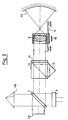
- FIG. 1 A further possibility for eliminating the tilting term while simultaneously increasing the sensitivity of the interferometer arrangement by a factor of 2 can be achieved if an optical double-pass arrangement is inserted into the test arm of the interferometer as shown in FIG.
- This consists of a polarizing beam splitter cube (13) on which the A so-called ⁇ / 4 plate (14) is placed on the side of the collimator (8).
- the test wave reflected by the test specimen (22) is then laterally reflected when it re-enters the polarizing beam splitter cube (13) and, after being deflected at a retroreflector (triple prism 15), is emitted again in the direction of the test specimen (22).
- the second test wave is point symmetrical to the optical axis compared to the first test wave.
- a triple mirror (40) in the reference arm which also rotates the reference shaft by 180 o , so that deviations in flatness of the plane shaft (19) entering the interferometer do not influence the measurement result.
- the same differences in the light path length on both sides of the optical axis, as they occur when tilting and offset, are automatically eliminated.
- this method can only be used for rotationally symmetrical test specimens.
- a test setup is shown in the measuring branch of the interferometer, with which lenses, and not only individual lenses but also partially assembled or complete optics, can be tested in one pass.
- the collimator is denoted by (18) and the test specimen by (32).
- a spherical autocollimation mirror (33) is inserted behind the optics to be checked. The radius of this autocollimation mirror (33) is selected so that it approximately corresponds to the wavefront generated by the test object (32) in a central position of the collimator (18).
- the asphericity of the test specimen (32) is now measured as described with reference to FIG. 1 in that the collimator (18) is moved into different positions relative to the test specimen (32) so that different aperture areas of the wavefront deformed aspherically by the test specimen (32) meet the condition for autocollimation, ie perpendicular incidence on the convex mirror (33).
- the optical path length for the beam running on the axis of the test arm of the interferometer remains in all positions of the Collimators the same, so that the wavefront does not change globally in this area. This also applies if, instead of the collimator (18), the optics (32) to be tested are axially displaced.
- the shape of the wavefront deformed by the test specimen (32) can be measured in absolute terms by moving the collimator (18) into a position in which the beam aperture apertures are the same on the object and image side, i.e. the focal lengths, for the optics (32) on both sides of the optics (32) are almost the same.
- the test specimen is removed from the beam path in the test branch of the interferometer and the spherical autocollimation mirror (33) is brought into the position shown there in the convergent beam path behind the collimator (18) and still exactly 180 ° around the optical one Axis rotates, the errors of the test arrangement, namely the wavefront distortions caused by the beam splitter (3) and the reference mirror (4) of the interferometer, as well as the errors of the collimator (18) and the autocollimation mirror (33) can be completely eliminated.
- the difference between the light path differences can simply be formed, which can be obtained from the evaluation of the interferograms in the two structures shown in FIG. 3 and FIG. 4 with and without the test object.
- the plane mirror (4) in the reference arm of the interferometer is replaced by a triple prism or the triple mirror (40) shown in broken lines in order to also rotate the reference shaft by 180 ° .
- the devices described with reference to FIGS. 1-4 are based on a Twyman-Green type interferometer. However, it is equally possible to carry out the method according to the invention on devices which are based on Mach-Zehnder interferometers. Such structures can be in particular for the measurement of transparent optics in transmission or non-rotationally symmetrical aspherical mirrors in reflection. Such a construction based on a Mach-Zehnder interferometer is shown in FIG. 5. Here, the incident plane wave is again designated with (19).
- the plane wave (19) is divided by a first beam splitter (23a) into the measuring and the test arm and the partial waves reflected at the two plane mirrors (24a and 24b) are combined again at the second beam splitter (23b) of the Mach-Zehnder interferometer. While the reference arm of the interferometer is empty, the lens (42) to be tested is located in the test arm of the interferometer between two collimator objectives (28 and 38).
- the collimator objectives (28 and 38) can either be corrected systems that transform plane waves into spherical waves, or, as shown in FIG. 5, single lenses. You do not necessarily have to have the same optical data.
- the test object (42) and the two collimators (28 and 38) can be moved along the optical axis in the test arm of the interferometer by means of the guide (39), as indicated by the arrows.
- two of the three components either the two collimators (28 and 38) or the test specimen (42) and one of the two collimators, are moved simultaneously, and the two vertex distances of the test specimen (42) to both collimators (28 and 38 ) with the help of a length measuring system drawn as a scale (41) for different distances.
- a length measuring system drawn as a scale (41) for different distances.
- an afocal optical system consisting of the two lenses (50 and 52) is arranged, which images the test specimen (42) sharply onto the subsequent CCD camera (5) and adapts the beam cross-section that emerges from the interferometer to the surface of the CCD camera (25).
- An aperture (51) is located in the intermediate focus of this afocal system (50, 52). This aperture (51) only allows rays from the compensated area of the test object to pass, in which the wavefront of the test wave is adapted to the asphericity of the test object (42). This prevents rays outside the compensated area from producing interfering interference on the photosensitive surface of the CCD camera (25).
- this optical system (50, 52) can also be placed in front of the CCD camera designated there (5).
- calibration measurements can again be carried out in order to eliminate wavefront errors caused by the collimators (28 and 38).
- the test specimen (42) is removed from the beam path and the two collimators (28 and 38) are moved towards one another such that the two focus points Q1 and Q2 coincide.
Landscapes
- Physics & Mathematics (AREA)
- Chemical & Material Sciences (AREA)
- Analytical Chemistry (AREA)
- General Physics & Mathematics (AREA)
- Geometry (AREA)
- Instruments For Measurement Of Length By Optical Means (AREA)
- Length Measuring Devices By Optical Means (AREA)
- Testing Of Optical Devices Or Fibers (AREA)
Claims (10)
- Procédé pour contrôler des éléments optiques, qui délivrent des fronts d'ondes asphériques, à l'aide d'un interféromètre, et selon lequel on déplace le collimateur, qui produit l'onde de contrôle, de l'interféromètre par rapport à l'objet à contrôler et on enregistre des interférogrammes dans différentes positions du collimateur, dans lesquelles des zones partielles de l'onde de contrôle sont adaptées à l'objet à contrôler,- on mesure avec une grande précision la position relative entre le collimateur (8;18;28,38) et l'objet à contrôler (12;22;32;42) dans les différentes positions,- on enregistre électroniquement les interférogrammes au moyen d'un capteur d'images (appareil de prise de vues 5; 25) et on les mémorise en tant que différences (lréelle(h)) du trajet de la lumière entre le faisceau de contrôle et le faisceau de référence de l'interféromètre pour les différents points d'image d'un interférogramme,- on compare les différences (lréelle(h)), mesurées de façon interférométrique, aux différences de consigne (lconsigne(h)) du trajet de la lumière, calculées pour les différentes positions du collimateur (8;18;28,38) ou déterminées par calibrage, les erreurs de phase (Δφ(h)) étant formées pour les différents points d'image, et- à partir de là on calcule les défauts de la forme asphérique du front d'onde de l'objet à contrôler (12;22; 32;42).
- Procédé selon la revendication 1, caractérisé en ce que le calcul de la forme du front d'onde inclut une formation de la valeur moyenne de telle sorte qu'on forme respectivement les différences des erreurs de phase (Δφ(h)) de points d'image voisins (xi, yi) et (xi + dx, yi) ainsi que de (xi, yi + dy), qu'on forme la moyenne de ces différences et qu'on l'intègre ensuite sur l'ensemble de l'erreur du front d'onde de l'objet à contrôler.
- Procédé selon la revendication 1, caractérisé en ce qu'on calcule au préalable la forme précise du front d'onde délivré par le collimateur (8,18;28,38), à partir des données de la lentille du collimateur et qu'on en tient compte pour la détermination de la différence de consigne (lconsigne(h)) du trajet de la lumière.
- Procédé selon la revendication 1, caractérisé en ce qu'on détermine au préalable la forme précise du front d'onde, qui sort du collimateur (8;18;28,38), au moyen d'une mesure de comparaison interférométrique par rapport à une surface de forme connue et qu'on en tient compte lors de la détermination des différences de consigne (lconsigne(h)) du trajet de la lumière.
- Procédé selon la revendication 1, caractérisé en ce que lors de chaque contrôle, on déplace le collimateur dans les deux directions (+z, -z) et qu'on forme la moyenne des valeurs de mesure obtenues pour les mêmes positions dans les deux cycles de déplacement.
- Dispositif pour contrôler des éléments optiques, qui délivre des fronts d'ondes asphériques, constitué par- un interféromètre (3,4,23,24),- un collimateur (8;18;28,38) qui produit l'onde de contrôle et est déplaçable par rapport à l'objet à contrôler (12;22;32;42),- un dispositif (5-7;25) pour enregistrer et représenter les interférogrammes;- un système de mesure de longueur (10,11;41) pour déterminer de façon précise la position relative entre l'objet à contrôler et le collimateur,et dans lequel- l'interféromètre possède un bras de référence séparé, et- le dispositif d'enregistrement des interférogrammes contient un calculateur (6), qui est agencé de telle sorte qu'il peut former les différences (Iréelle(h)) du trajet de lumière, déterminées à partir des interférogrammes et les différences (lconsigne(h)) du trajet de la lumière, calculées à partir de la forme de l'onde de contrôle et à partir de la forme de consigne de l'objet à contrôler, pour chaque point d'image et dans chaque position (s(h)) de l'objectif du collimateur.
- Dispositif selon la revendication 6, caractérisé en ce que le collimateur (8) est une lentille individuelle.
- Dispositif selon la revendication 7, caractérisé en ce que l'objet à contrôler est une lentille ou un système de lentilles (32) et est disposé en arrière de l'objet et qu'un miroir (33;34) est disposé en arrière de l'objet à contrôler.
- Dispositif selon la revendication 6, caractérisé en ce qu'un dispositif d'adaptation optique double (13-15) est inséré entre l'interféromètre (3,4) et le collimateur (8).
- Dispositif selon la revendication 6, caractérisé en ce que l'objet à contrôler (42) est disposé entre deux collimateurs (28,38) dans le bras de mesure d'un interféromètre de Mach-Zehnder.
Priority Applications (1)
| Application Number | Priority Date | Filing Date | Title |
|---|---|---|---|
| AT89119245T ATE98017T1 (de) | 1988-10-27 | 1989-10-17 | Interferometrisches verfahren zur pruefung von asphaerische wellenfronten erzeugenden optischen elementen. |
Applications Claiming Priority (2)
| Application Number | Priority Date | Filing Date | Title |
|---|---|---|---|
| DE3836564 | 1988-10-27 | ||
| DE3836564A DE3836564A1 (de) | 1988-10-27 | 1988-10-27 | Verfahren zur pruefung von optischen elementen |
Publications (3)
| Publication Number | Publication Date |
|---|---|
| EP0370229A2 EP0370229A2 (fr) | 1990-05-30 |
| EP0370229A3 EP0370229A3 (fr) | 1991-12-04 |
| EP0370229B1 true EP0370229B1 (fr) | 1993-12-01 |
Family
ID=6366004
Family Applications (1)
| Application Number | Title | Priority Date | Filing Date |
|---|---|---|---|
| EP89119245A Expired - Lifetime EP0370229B1 (fr) | 1988-10-27 | 1989-10-17 | Procédé interférométrique d'essai d'éléments optiques produisant des fronts d'onde asphériques |
Country Status (6)
| Country | Link |
|---|---|
| US (1) | US5004346A (fr) |
| EP (1) | EP0370229B1 (fr) |
| JP (1) | JPH02170033A (fr) |
| AT (1) | ATE98017T1 (fr) |
| CA (1) | CA2001612A1 (fr) |
| DE (2) | DE3836564A1 (fr) |
Cited By (1)
| Publication number | Priority date | Publication date | Assignee | Title |
|---|---|---|---|---|
| US7522292B2 (en) | 2005-03-11 | 2009-04-21 | Carl Zeiss Smt Ag | System and method for determining a shape of a surface of an object and method of manufacturing an object having a surface of a predetermined shape |
Families Citing this family (43)
| Publication number | Priority date | Publication date | Assignee | Title |
|---|---|---|---|---|
| US5293214A (en) * | 1991-12-06 | 1994-03-08 | Hughes Aircraft Company | Apparatus and method for performing thin film layer thickness metrology by deforming a thin film layer into a reflective condenser |
| US5355210A (en) * | 1991-12-20 | 1994-10-11 | Rotlex Optics Ltd. | Method and apparatus for measuring optical properties of optical devices |
| US5305074A (en) * | 1992-07-17 | 1994-04-19 | The United States Of America As Represented By The United States Department Of Energy | Achromatic self-referencing interferometer |
| US5416586A (en) * | 1993-10-15 | 1995-05-16 | Tropel Corporation | Method of testing aspherical optical surfaces with an interferometer |
| US5473434A (en) * | 1994-05-16 | 1995-12-05 | Zygo Corporation | Phase shifting interferometer and method for surface topography measurement |
| US5625454A (en) * | 1995-05-24 | 1997-04-29 | Industrial Technology Research Institute | Interferometric method for optically testing an object with an aspherical surface |
| DE19637397C2 (de) * | 1995-09-13 | 2000-11-30 | Toshiba Kawasaki Kk | Ultraschall-Meßkopf und Verfahren zur Herstellung eines Oxid-Monokristalls |
| JPH102714A (ja) * | 1996-06-19 | 1998-01-06 | Canon Inc | 測定方法及び装置 |
| DE19708447A1 (de) * | 1997-03-01 | 1998-09-03 | Ingolf Dr Weingaertner | Vorrichtung und Verfahren für die Justierung von Twyman-Interferometern |
| US6791696B1 (en) * | 1998-06-18 | 2004-09-14 | Optikos Corporation | Automated optical measurement apparatus and method |
| DE19944021A1 (de) * | 1998-09-14 | 2000-05-04 | Nikon Corp | Interferometrische Vorrichtung und Verfahren zum Vermessen der Oberflächentopographie einer Testoberfläche |
| US6750958B1 (en) | 1999-06-09 | 2004-06-15 | Optikos Corporation | Automated optical measurement apparatus and method |
| US6771375B2 (en) * | 2001-06-20 | 2004-08-03 | Zygo Corporation | Apparatus and method for measuring aspherical optical surfaces and wavefronts |
| US6781700B2 (en) * | 2001-06-20 | 2004-08-24 | Kuechel Michael | Scanning interferometer for aspheric surfaces and wavefronts |
| US6972849B2 (en) * | 2001-07-09 | 2005-12-06 | Kuechel Michael | Scanning interferometer for aspheric surfaces and wavefronts |
| US6788423B2 (en) * | 2001-08-31 | 2004-09-07 | Digital Optics Corp. | Conic constant measurement methods for refractive microlenses |
| WO2003021184A1 (fr) * | 2001-09-04 | 2003-03-13 | Zygo Corporation | Matriçage in situ rapide d'un interferometre de fizeau aspherique |
| US6734979B2 (en) * | 2001-11-15 | 2004-05-11 | Zygo Corporation | Rapid in situ mastering of an aspheric Fizeau with residual error compensation |
| WO2003044454A1 (fr) * | 2001-11-15 | 2003-05-30 | Zygo Corporation | Optiques zero dispersives pour metrologie de front d'onde et de surface aspherique |
| US6879402B2 (en) * | 2001-11-16 | 2005-04-12 | Zygo Corporation | Scanning interferometer for aspheric surfaces and wavefronts |
| JP4094301B2 (ja) * | 2002-02-06 | 2008-06-04 | フジノン株式会社 | 干渉計用基準レンズ |
| KR100443985B1 (ko) | 2002-02-14 | 2004-08-11 | 삼성전자주식회사 | 콜리메이터 검사장치 |
| KR100418711B1 (ko) | 2002-02-20 | 2004-02-14 | 삼성전자주식회사 | 콜리메이터 특성 검사장치 |
| US7218403B2 (en) * | 2002-06-26 | 2007-05-15 | Zygo Corporation | Scanning interferometer for aspheric surfaces and wavefronts |
| US6943896B2 (en) | 2003-10-20 | 2005-09-13 | Zygo Corporation | Reconfigurable interferometer system |
| US7289222B1 (en) | 2003-10-31 | 2007-10-30 | Carl Zeiss Smt Ag | Interferometer apparatus and method of processing a substrate having an optical surface |
| US20050225774A1 (en) * | 2004-04-05 | 2005-10-13 | Carl Zeiss Smt Ag | Method for measuring and manufacturing an optical element and optical apparatus |
| US7612893B2 (en) * | 2006-09-19 | 2009-11-03 | Zygo Corporation | Scanning interferometric methods and apparatus for measuring aspheric surfaces and wavefronts |
| JP5305741B2 (ja) * | 2008-05-29 | 2013-10-02 | キヤノン株式会社 | 測定方法 |
| US8294904B2 (en) * | 2008-05-29 | 2012-10-23 | Corning Incorporated | Fizeau lens having aspheric compensation |
| JP5430473B2 (ja) * | 2009-10-01 | 2014-02-26 | キヤノン株式会社 | 面形状計測装置 |
| JP5430472B2 (ja) * | 2009-10-01 | 2014-02-26 | キヤノン株式会社 | 面形状計測装置 |
| JP5486379B2 (ja) * | 2009-10-01 | 2014-05-07 | キヤノン株式会社 | 面形状計測装置 |
| JP5618727B2 (ja) * | 2010-09-21 | 2014-11-05 | キヤノン株式会社 | 形状測定法及び形状計測装置 |
| EP2710330B1 (fr) * | 2011-05-20 | 2016-02-10 | Universitat Politécnica De Catalunya | Procédé et dispositif pour mesurer des surfaces sans contact |
| JP6042213B2 (ja) * | 2013-01-10 | 2016-12-14 | 株式会社日立ハイテクノロジーズ | 凹面光学素子の測定装置及び凹面回折格子の測定装置並びに平面回折格子の測定装置 |
| US9128030B1 (en) | 2013-03-06 | 2015-09-08 | The Boeing Company | X-ray backscattering battery inspection |
| US9781412B2 (en) | 2015-02-04 | 2017-10-03 | Sony Corporation | Calibration methods for thick lens model |
| CN106989693B (zh) * | 2017-05-12 | 2022-10-21 | 中国工程物理研究院激光聚变研究中心 | 一种离轴椭球镜面形检测装置及其检测方法 |
| DE102019204578A1 (de) * | 2019-04-01 | 2020-10-01 | Carl Zeiss Meditec Ag | Prüfvorrichtung und Verfahren zur Vermessung der Homogenität eines optischen Elements |
| US12305976B2 (en) | 2020-06-15 | 2025-05-20 | Bmv Optical Technologies Inc. | Optical system using enhanced static fringe capture |
| CN112762817B (zh) * | 2020-12-23 | 2022-07-08 | 广东工业大学 | 倾斜斐索波数扫描干涉仪 |
| CN115435677B (zh) * | 2022-08-17 | 2024-09-27 | 中国科学院光电技术研究所 | 一种通用于双通道干涉仪的系统误差标定装置和标定方法 |
Family Cites Families (8)
| Publication number | Priority date | Publication date | Assignee | Title |
|---|---|---|---|---|
| US3740750A (en) * | 1962-08-29 | 1973-06-19 | North American Aviation Inc | Monopulse receiver system |
| US4074937A (en) * | 1976-02-09 | 1978-02-21 | Zygo Corporation | Optical measuring device |
| US4387994A (en) * | 1980-02-04 | 1983-06-14 | Balasubramanian N | Optical system for surface topography measurement |
| US4396289A (en) * | 1980-10-28 | 1983-08-02 | Polaroid Corporation | Method and apparatus for holographic testing of optical components |
| US4435079A (en) * | 1981-08-28 | 1984-03-06 | American Optical Corporation | Apparatus for testing lenses by determining best focus |
| US4696572A (en) * | 1985-02-19 | 1987-09-29 | Kabushiki Kaisha Toshiba | Surface inspection apparatus |
| US4697927A (en) * | 1985-11-29 | 1987-10-06 | Kabushiki Kaisha Toshiba | Method and apparatus for measuring a forming error of an object |
| JPS62168008A (ja) * | 1986-01-20 | 1987-07-24 | Ricoh Co Ltd | 非球面形状測定装置 |
-
1988
- 1988-10-27 DE DE3836564A patent/DE3836564A1/de not_active Withdrawn
-
1989
- 1989-10-17 EP EP89119245A patent/EP0370229B1/fr not_active Expired - Lifetime
- 1989-10-17 AT AT89119245T patent/ATE98017T1/de not_active IP Right Cessation
- 1989-10-17 DE DE89119245T patent/DE58906308D1/de not_active Expired - Fee Related
- 1989-10-26 CA CA002001612A patent/CA2001612A1/fr not_active Abandoned
- 1989-10-26 US US07/426,772 patent/US5004346A/en not_active Expired - Lifetime
- 1989-10-27 JP JP1278795A patent/JPH02170033A/ja active Pending
Cited By (1)
| Publication number | Priority date | Publication date | Assignee | Title |
|---|---|---|---|---|
| US7522292B2 (en) | 2005-03-11 | 2009-04-21 | Carl Zeiss Smt Ag | System and method for determining a shape of a surface of an object and method of manufacturing an object having a surface of a predetermined shape |
Also Published As
| Publication number | Publication date |
|---|---|
| CA2001612A1 (fr) | 1990-04-27 |
| US5004346A (en) | 1991-04-02 |
| DE58906308D1 (de) | 1994-01-13 |
| EP0370229A3 (fr) | 1991-12-04 |
| EP0370229A2 (fr) | 1990-05-30 |
| DE3836564A1 (de) | 1990-05-03 |
| JPH02170033A (ja) | 1990-06-29 |
| ATE98017T1 (de) | 1993-12-15 |
Similar Documents
| Publication | Publication Date | Title |
|---|---|---|
| EP0370229A2 (fr) | Procédé interférométrique d'essai d'éléments optiques produisant des fronts d'onde asphériques | |
| DE102015001421B4 (de) | Vorrichtung und Verfahren zur Strahldiagnose an Laserbearbeitungs-Optiken (PRl-2015-001) | |
| EP0126475B1 (fr) | Procédé et dispositif pour la mesure sans contact de la position instantanée et/ou de la rugosité de surfaces | |
| DE19782060B4 (de) | Interferometer mit katadioptrischem Abbildungssystem mit erweitertem numerischem Aperturbereich | |
| DE102017128158A9 (de) | Abstandsmessungsvorrichtung und Verfahren zur Messung von Abständen | |
| DE102011004376B3 (de) | Verfahren und Vorrichtung zum Bestimmen einer Form einer optischen Testfläche | |
| CH693968A5 (de) | Verfahren und Vorrichtung fuer die Topographiepruefung von Oberflaechen. | |
| WO2008012091A2 (fr) | Procédé et dispositif de détermination de l'écart d'une forme réelle de la forme nominale d'une surface optique | |
| EP3084344B1 (fr) | Procédé pour mesurer une surface optique sphériquement astigmate | |
| DE102008049159B4 (de) | Verfahren und Vorrichtung zur optischen Messung langer Krümmungsradien optischer Prüfflächen | |
| WO2015150301A1 (fr) | Procédé pour ajuster un miroir d'un appareil d'éclairement par projection microlithographique | |
| DE102015220588A1 (de) | Messverfahren und Messanordnung für ein abbildendes optisches System | |
| DE102018111466B4 (de) | Verfahren zur justage einer messvorrichtung mittels eines justagekörpers, justagekörper und verfahren zur justage eines justagekörpers | |
| DE102022209651A1 (de) | Verfahren zum Bearbeiten eines Referenzelements für ein Interferometer | |
| DE102022201462A1 (de) | Messvorrichtung zur Bestimmung einer Form einer optischen Oberfläche eines Prüflings | |
| DE4413758C2 (de) | Vorrichtung und Verfahren zur Prüfung der Gestalt einer Oberfläche eines zu vermessenden Objektes | |
| DE10325601B3 (de) | Schaltbares Punktlichtquellen-Array und dessen Verwendung in der Interferometrie | |
| DE102007021953B4 (de) | Interferometrische Messvorrichtung zum Vermessen einer Oberfläche eines Prüflings | |
| EP1805476B1 (fr) | Interferometre comprenant un systeme de miroirs pour effectuer des mesures sur un objet | |
| DE102006057606B4 (de) | Verfahren und Messvorrichtung zur Vermessung einer optisch glatten Oberfläche | |
| DE102015209489A1 (de) | Interferometrische Messvorrichtung | |
| WO2019206371A1 (fr) | Procédé et dispositif de contrôle de propriétés géométriques de composants optiques | |
| DE102022210483A1 (de) | Interferometrische Messvorrichtung | |
| DE102017001524B4 (de) | Anordnung zur Vermessung zumindest teilweise reflektierender Oberflächen | |
| DE4242882C2 (de) | Verfahren zum Prüfen asphärisch gekrümmter Oberflächen und Interferometer-Anordnung hierfür |
Legal Events
| Date | Code | Title | Description |
|---|---|---|---|
| PUAI | Public reference made under article 153(3) epc to a published international application that has entered the european phase |
Free format text: ORIGINAL CODE: 0009012 |
|
| AK | Designated contracting states |
Kind code of ref document: A2 Designated state(s): AT CH DE FR GB IT LI NL SE |
|
| PUAL | Search report despatched |
Free format text: ORIGINAL CODE: 0009013 |
|
| AK | Designated contracting states |
Kind code of ref document: A3 Designated state(s): AT CH DE FR GB IT LI NL SE |
|
| 17P | Request for examination filed |
Effective date: 19920602 |
|
| 17Q | First examination report despatched |
Effective date: 19930212 |
|
| ITF | It: translation for a ep patent filed | ||
| GRAA | (expected) grant |
Free format text: ORIGINAL CODE: 0009210 |
|
| AK | Designated contracting states |
Kind code of ref document: B1 Designated state(s): AT CH DE FR GB IT LI NL SE |
|
| REF | Corresponds to: |
Ref document number: 98017 Country of ref document: AT Date of ref document: 19931215 Kind code of ref document: T |
|
| REF | Corresponds to: |
Ref document number: 58906308 Country of ref document: DE Date of ref document: 19940113 |
|
| GBT | Gb: translation of ep patent filed (gb section 77(6)(a)/1977) |
Effective date: 19940124 |
|
| ET | Fr: translation filed | ||
| PLBE | No opposition filed within time limit |
Free format text: ORIGINAL CODE: 0009261 |
|
| STAA | Information on the status of an ep patent application or granted ep patent |
Free format text: STATUS: NO OPPOSITION FILED WITHIN TIME LIMIT |
|
| 26N | No opposition filed | ||
| EAL | Se: european patent in force in sweden |
Ref document number: 89119245.2 |
|
| PGFP | Annual fee paid to national office [announced via postgrant information from national office to epo] |
Ref country code: GB Payment date: 19960916 Year of fee payment: 8 |
|
| PGFP | Annual fee paid to national office [announced via postgrant information from national office to epo] |
Ref country code: CH Payment date: 19960920 Year of fee payment: 8 Ref country code: FR Payment date: 19960920 Year of fee payment: 8 |
|
| PGFP | Annual fee paid to national office [announced via postgrant information from national office to epo] |
Ref country code: AT Payment date: 19960923 Year of fee payment: 8 Ref country code: SE Payment date: 19960923 Year of fee payment: 8 |
|
| PGFP | Annual fee paid to national office [announced via postgrant information from national office to epo] |
Ref country code: NL Payment date: 19960930 Year of fee payment: 8 |
|
| PG25 | Lapsed in a contracting state [announced via postgrant information from national office to epo] |
Ref country code: AT Free format text: LAPSE BECAUSE OF NON-PAYMENT OF DUE FEES Effective date: 19971017 Ref country code: GB Free format text: LAPSE BECAUSE OF NON-PAYMENT OF DUE FEES Effective date: 19971017 |
|
| PG25 | Lapsed in a contracting state [announced via postgrant information from national office to epo] |
Ref country code: SE Free format text: LAPSE BECAUSE OF NON-PAYMENT OF DUE FEES Effective date: 19971018 |
|
| PG25 | Lapsed in a contracting state [announced via postgrant information from national office to epo] |
Ref country code: LI Free format text: LAPSE BECAUSE OF NON-PAYMENT OF DUE FEES Effective date: 19971031 Ref country code: CH Free format text: LAPSE BECAUSE OF NON-PAYMENT OF DUE FEES Effective date: 19971031 Ref country code: FR Free format text: THE PATENT HAS BEEN ANNULLED BY A DECISION OF A NATIONAL AUTHORITY Effective date: 19971031 |
|
| PG25 | Lapsed in a contracting state [announced via postgrant information from national office to epo] |
Ref country code: NL Free format text: LAPSE BECAUSE OF NON-PAYMENT OF DUE FEES Effective date: 19980501 |
|
| GBPC | Gb: european patent ceased through non-payment of renewal fee |
Effective date: 19971017 |
|
| REG | Reference to a national code |
Ref country code: CH Ref legal event code: PL |
|
| NLV4 | Nl: lapsed or anulled due to non-payment of the annual fee |
Effective date: 19980501 |
|
| EUG | Se: european patent has lapsed |
Ref document number: 89119245.2 |
|
| REG | Reference to a national code |
Ref country code: FR Ref legal event code: ST |
|
| PG25 | Lapsed in a contracting state [announced via postgrant information from national office to epo] |
Ref country code: IT Free format text: LAPSE BECAUSE OF NON-PAYMENT OF DUE FEES Effective date: 20051017 |
|
| PGFP | Annual fee paid to national office [announced via postgrant information from national office to epo] |
Ref country code: DE Payment date: 20071025 Year of fee payment: 19 |
|
| PG25 | Lapsed in a contracting state [announced via postgrant information from national office to epo] |
Ref country code: DE Free format text: LAPSE BECAUSE OF NON-PAYMENT OF DUE FEES Effective date: 20090501 |