EP0370352A2 - An apparatus for curing a coating on a moving substrate and a method of operating the apparatus - Google Patents
An apparatus for curing a coating on a moving substrate and a method of operating the apparatus Download PDFInfo
- Publication number
- EP0370352A2 EP0370352A2 EP89120983A EP89120983A EP0370352A2 EP 0370352 A2 EP0370352 A2 EP 0370352A2 EP 89120983 A EP89120983 A EP 89120983A EP 89120983 A EP89120983 A EP 89120983A EP 0370352 A2 EP0370352 A2 EP 0370352A2
- Authority
- EP
- European Patent Office
- Prior art keywords
- temperature
- liquid
- reflector
- block
- refrigerating
- Prior art date
- Legal status (The legal status is an assumption and is not a legal conclusion. Google has not performed a legal analysis and makes no representation as to the accuracy of the status listed.)
- Granted
Links
Images

Classifications
-
- B—PERFORMING OPERATIONS; TRANSPORTING
- B41—PRINTING; LINING MACHINES; TYPEWRITERS; STAMPS
- B41F—PRINTING MACHINES OR PRESSES
- B41F23/00—Devices for treating the surfaces of sheets, webs, or other articles in connection with printing
- B41F23/04—Devices for treating the surfaces of sheets, webs, or other articles in connection with printing by heat drying, by cooling, by applying powders
- B41F23/0403—Drying webs
- B41F23/0406—Drying webs by radiation
- B41F23/0409—Ultraviolet dryers
Definitions
- This invention relates to an improved system and method for photochemically curing a heat-sensitive coating on a moving substrate. More particularly the system and method are applicable to curing of a heat sensitive coating on a moving substrate so as to minimize problems related to heating and provide apparatus of reduced size for use in presses where only a very limited amount of space is available, at one or more locations, for a curing system.
- Air alone or with water, is the usual medium for cooling lamp reflector assemblies. Most commonly air for cooling such assemblies is provided by low pressure, large-volume blowers which operate between about 1/8 to 1/4 psi. and provide between about 350 to 1500 cfm. The large-volume blowers generate large amounts of air which must be exhausted from the presses and further create large amounts of undesirable ozone which also mus& be exhausted in a controlled manner from the vicinity of the presses. Occasionally, air for cooling is supplied from a plant compressed air system which has a blower that operates at high pressure and low volume, i.e. about 60 to 80 psi. or higher, and at about 8 to 10 cfm.
- Another object is to provide such a system which includes curing apparatus that is of a size that can be readily mounted within such a press and can be cooled in a controlled mannner substantially completely by water circulated therethrough by equipment mounted external of the press.
- Another object is to provide a method for operating such a system in a controlled manner such that the system effectively reacts to variations in press conditions and controls the operation of the press lamp-reflector assembly within prescribed temperature ranges.
- An object of the invention is accomplished by a system for curing a coating on a substrate moving through a multi-stand press.
- the curing is accomplished by means of ultraviolet radiation from a mercury vapor lamp-reflector assembly mounted within the limited confines of the press.
- the assembly comprises an elongated reflector-block, which has a cavity with a parabolic trough reflective surface, and an ultraviolet lamp mounted within the cavity.
- the reflector-block includes a longitudinally extending channel at the apex of the cavity, a water conduit and an air conduit. A plurality of ports connect the air conduit with the reflector-block channel.
- a water pump circulates water to and from the reflector-block water conduit for cooling purposes.
- First and second intermediate pressure blowers connected in series convey pressurized air to a heat exchanger, which is connected to a refrigerating device, and then sequentially to the reflector-block air conduit, ports and channel from where it is discharged to flow over the ultraviolet lamp and block reflective surface.
- a temperature measuring device positioned within the reflector-block cavity transmits temperature variations adjacent the ultraviolet lamp to a computer.
- the computer is connected to the blowers, refrigerating device and heat exchanger and functions to modify the operations thereof in accordance with the temperature transmitted to the computer by the temperature measuring device whereby the system reacts to variations in press conditions and controls the lamp-reflector assembly in a manner to operate within a prescribed temperature range.
- the objectives are accomplished by a method of operating the system described above in the following manner.
- the temperature of an ultraviolet lamp for curing the coating on a moving substrate and mounted within the cavity of a reflector-black is controlled within a prescribed temperature range by continuously monitored temperatures adjacent the lamp.
- Changes in temperature transmitted to a computer control device initiate, in a staged manner, the operation of first and second blowers, a heat exchanger and refrigerating device to reduce the temperature of pressurized air delivered to the reflector-block and discharged therefrom over and around the lamp to maintain its operation within a prescribed temperature range.
- Water in a controlled manner is also circulated through the reflector-block for cooling purposes anmd provide a stabilizing reference point for the temperature devices.
- the apparatus in another variation of the invention in which the system is substantially completely cooled by water, includes a lamp-reflector assembly, refrigerating device, and reservoir water circulation system and control system for monitoring and regulating the temperature of water circulated through the lamp-reflector assembly.
- the lamp-reflector assembly includes a reflector block with a generally smooth outer surface, having a cavity with a refective surface, two conduits extending through the reflector block and an elongated ultraviolet lamp positioned fully within the reflector block cavity.
- the water circulation system includes a pump and associated tubing to circulate water from the refrigerating device reservoir, through the reflector block conduits and back to the refrigerating device.
- the control system includes a temperature measuring device within the refrigerating device reservoir, a computer and appropriate lines connecting the temperature measuring device, computer and refrigerating device for mounting and controlling within a desired range the temperature of the refrigerated water circulated through the reflector block.
- the objectives are accomplished by a method of operating the system which is substantially completely cooled by water.
- the control system temperature measuring device monitors the temperature of the water in the refrigerating device reservoir and communicates an applicable signal to the control system computer. When the temperature is not within a desired range, the computer signals the refrigerating device to start or shut-off, as appropriate. In this manner the temperature of refrigerated water circulated to and through the conduits of the reflector block is maintained within a temperature range that permits most efficient operation.
- Feed chain 2 shown in greater detail in Figure 7, moves from the multi-stand section of the press, not shown, in the direction of arrow A along bottom pass line B. Chain 2 continues along the bottom pass line B, upwardly and over guide roller 3 around drive sprocket 4, where it reverses directiion. Chain 2 then travels along upper pass line C, over sprocket 5 and downwardly and from delivery section 1 in the direction of arrow D and returns to the multi-stand section of the press.
- each sheet 7 Spaced along chain 2 are a plurality of releasable clamps 6 that engage the leading edges of sheets 7 which rest on chain 2.
- a thin coating 9 of ink or chemical that has been placed on surface 8 during the passage of sheets 7 through the multi-stand section of the press.
- clamps 6 which engage the leading edge of the sheet release, and it drop through delivery section opening 10 onto the top of a stack 11 of sheets 7 from where they can be moved subsequently to a desired location.
- Exhaust blower 12 continuously removes hot air from the interior of delivery section 1.
- each lamp assembly 20 includes elongated tubular, medium-pressure mercury vapor ultraviolet lamp 21, a line source of light, having a central portion 22 in which there is formed an arc, shown in Figure 7, that emits radiation, and end portions 23 and 24.
- Wires 25 and 26 of and portions 23 and 24, respectively, of lamp 21 are connected to a suitable power source, not shown, for energizing lamp 21.
- Lamp end portions 23 and 24 are mounted in refractory insulators 27 and 28, respectively, secured to opposite ends of elongated reflector-block 30.
- reflector-block 30 which is made of extruded aluminum, has an upper portion 31 and a lower portion 32 and a cavity 33 in the shape of a parabolic trough having a reflective surface 34.
- reflector-block 30 has a top 35, side 36, stepped side 37 and ends 38 and 39.
- channel 40 At the apex of reflective surface 34 is channel 40 that extends longitudinally of block 30 from end 38 to end 39.
- Water conduit 41 is positioned in the upper portion 31 of block 30, between reflective surface 34 and block top 35 and side 36.
- Air conduit 42 is positioned in the upper portion 31 of block 30, between channel 40 and top 35.
- System 60 includes intermediate pressure blowers 61 and 62, which are connected in series, heat exchanger 70, refrigerating device 80 and computer control device 90.
- Air is supplied to blower 61 through air inlet tubing 63 and air filter 64.
- blower 61 the air is pressurized and its temperature elevated somewhat before being discharged through connecting tube 65 to blower 62 where the air is further pressurized and its temperature again elevated.
- the pressurized, heated air then passes through tube 66 to and through a first side of shell and tube heat exchanger 70 where the pressurized air is cooled as hereinafter described.
- the cooled pressurized air then passes through cooled air discharge line 67 to air inlet tubing 47 and to air conduit 42 of each lamp assembly 20.
- the cooled, pressurized air passes into air conduit 42 and discharges through ports 43 and reflector-block channel 40, at between about 1/4 to 1/2 cfm. per linear inch of length, as shown in Figure 4 by arrows E, over and around lamp 21 to uniformly cool it and maintain its temperature within a prescribed operating range, i.e. between about 1100 o F to 1500 o F.
- the pressurized heated air passing through one side of heat exchanger 70 has its temperature lowered by coolant that circulates from refrigerating device 80 through coolant tube 81 to a second side of heat exchanger 70 where the coolant extracts heat from the pressurized air in the first side thereof.
- the coolant at a higher temperature exits heat exchanger 70 and returns through coolant tube 82 to refrigerating device 80 where the temperature of the coolant is lowered in a manner wall known to those skilled in the art.
- each reflector-block 30 is also cooled by water circulated in a closed loop through refrigerating device 80, water feed tube 102 and water inlet tubing 45, water conduit 41 and water discharge tubing 46 of each such block back to refrigerating device 80. Circulation is accomplished by water pump 46A connected to discharge tube 46. Water is initially provided to the closed loop through water supply tube 100, from a source not shown, which connects to refrigerating device 80 and water feed tube 102 therein but not shown. Any replenishment of water is provided in the same manner.
- the cooled water passing through water conduit 41 of each reflector block 30 acts to maintain its temperature within a prescribed operating range of between about 50 o F. to 80 o F., preferably about 65 o F. In passing through reflector-block 30, the water temperature rises and it returns through water discharge tubing 46 and pump 46A to refrigerating device 80 where the water is recooled.
- the objectives are accomplished by a method of operating the above described system in the following manner.
- pump 46A operates to circulate water through reflector-block 30 to bring it within preference temperature of between about 45 o F. to 75 o F., preferably about 50 o F.
- Temperature sensing device 49 connected to computer control device 90, continually monitors the temperature within the vicinity of its position adjacent block reflective surface 34 and lamp 21, and when that temperature exceeds 75 o F.
- computer control device 90 through line 93 starts refrigerating device 80 to cool the water circulating through device 80.
- the press operator strikes lamp 21, i.e. turns on the power, initiating an arc within its central portion 22, and lamp 21 reaches full power in about 2 minutes.
- lamp 21 reaches full power in about 2 minutes.
- computer control device 90 through line 91 starts intermediate pressure blower 61 which draws air through air inlet tube 63 and filter 64 and compresses it to a pressure of between about 1/2 psi. to 1 psi. and increases the temperature thereof.
- the air to blower 61 has an ambient temperature of about 70 o F.
- the temperature of the pressurized air increases to about 90 o F.
- Pressurized air from blower 1 circulates through the appropriate tubing through intermediate pressure blower 62, which is inactive, heat exchanger 70, which is also inactive, to reflector-block 30 where the air passes into air conduit 42 and is discharged through ports 43 and channel 40 over lamp 21 and reflective surface 34 of such block.
- blower 61 Even as the pressurized air from blower 61 is discharged over lamp 21, its operating temperature continues to increase, as do the temperatures monitored by sensing device 49.
- control device 90 through line 92 starts intermediate pressure blower 62 connected in series with blower 61.
- Blower 62 through tube 65 receives pressurized heated air from blower 61 and further compresses it to a pressure between about 1.5 psi. to 1.75 psi., further increasing its temperature.
- the further pressurized and hotter air circulates through heat exchanger 70, which remains inactive, and to reflector-block 30 in the manner described in the preceding paragraph.
- the air discharged from blower 62 has a temperature of between about 90 o F. to 130 o F., preferably about 110 o F.
- control device 90 When the temperature communicated by temperature sensing device 49 to computer control device 90 rises to between about 650 o F. to 750 o F., control device 90, through line 93 starts refrigerating device 80 which circulates coolant through line 81, heat exchanger 70 and coolant return tube 82 back to device 80.
- the heated and pressurized air passing through a first side of heat exchanger 70 is cooled by the passage of coolant from refrigerating device 81 circulated through the second side of heat exchanger 70 in a manner to decrease the temperature of the pressurized air between about 30 o F. to 50 o F.
- the heated, pressurized air passing through heat exchanger 70 is cooled to a temperature between about 50 o F. to 80 o F., preferably about 60 o F. and passes to and from reflector-block 30 through channel 40 and over the surface of lamp 21 and block reflective surface 34 to cool those elements.
- the preferred embodiment of the system described above and its method of operation is used in conjunction with a press that is programmed to operate at four different stages of power, i.e. 1/4, 1/2, 3/4 or full power and computer control device 90, responding to temperatures communicated to it from temperature sensing device 49, functions to activate blower 61, blower 62, refrigerating device 80 and heat exchanger 70 in the manner described above.
- Other dryer systems incorporated in commercial presses do not operate in the 4-stage manner described above and operate only at 1/2 or full power.
- the cooling air blower is started at approximately the same time that the lamp arc is struck, and the air, at times, tends to over-cool the lamp and cause the arc to extinguish. Because of such early cooling present commercially available ultraviolet systems require between about 3 to 5 minutes for the ultraviolet lamp to reach full power.
- Figure 7 is illustrated a manner in which the lamp reflector assembly 20 of the preferred system described above may be installed between the bottom pass line B and the upper pass line C of chain 2.
- the distance L between such pass lines may be only between about 3 inches to 6 inches.
- the air and water cooling of the lamp-reflector assembly 20 it can be manufactured with an overall height H of between about 2-3/4 inches to 3-1/4 inches, with a width W of between about 2 inches to 3-1/2 inches.
- channel 40 may have a width w between about 3/64 inch to 9/64 inch, preferably about 1/16 inch
- water conduit 41 and air conduit 42 each may have a diameter d between about 3/8 inch to 3/4 inch.
- the diameter of lamp 21 may be between about 3/4 inch to 1-3/16 inches.
- the length of lamp 21 governs the length of reflector-block 30, channel 40 and ports 43. It is important that channel 40 have a length at least equal to the central portion 22 of lamp 21 to ensure adequate cooling of the central portion.
- Preferably elongated channel 40 should be at least as long as the overall length of lamp 21, i.e. including lamp end 23, central portion 22 and end 24 to ensure that the ends of the lamp receive adequate cooling.
- One of the advantages of the elongated channel 40 is that the pressurized air passing therefrom flows over and around lamp 21 to cool the surface thereof in a uniform manner.
- the arrows F in Figure 7 illustrate the manner in which rays reflect in a parallel manner from parabolic trough reflective surface 34.
- Blowers 61 and 62 have been identified as intermediate pressure blowers.
- An intermediate pressure blower is one that operates at a pressure of about 1/2 to 4 psi. with an output of between about 50 to 420 cfm.
- One blower meeting such requirements is a regenerative blower made by Gast Manufacturing Corp. of Benton Harbor, Michigan. This blower has blades only at the periphery of the impeller and as the blower impeller rotates, centrifugal force moves air from the root of the blade to the blade tip. Upon leaving the blade tip the air flows around the impeller housing contour back to the root of the succeeding blade where the flow pattern is repeated. This action provides a quasi-staging effect to increase pressure differential capability.
- computer control device 90 is an open board computer manufactured by Analog Device, Inc. of Norwood, Massachusetts.
- Refrigerating device 80 includes a condensing unit manufactured by Copeland Corporation of Sidney, Ohio.
- Heat exchanger 70 is a shell and tube heat exchanger manufactured by Trantor Division of ITT Corporation.
- Reflector-block 30 of extruded aluminum which provides adequate strength to support an ultraviolet lamp, which has a length of up to 60 inches and operates at a temperature of about 1100 o F., without sagging and damaging the lamp. While the preferred embodiment of reflector-block 30 includes a plurality of ports 43 separated by ribs 44, there can be one single port having a length approximately equal to that of channel 40. Ribs 44 strengthen and provide rigidity for reflector block 30 and prevent it from sagging and deteriorating under the high oerating conditions of lamp 21.
- a curing system that is substantially completely cooled by refrigerated water. It is also desirable to have a system in which the radiation striking the coated substrate is substantially the same as the radiation from the originating source, i.e. from the lamp and reflective surface of the reflector-block assembly. Such a system shall be referred to as one having a "uniform refractive index". Putting it another way, it is desirable to have a substantially completely water cooled system which avoids the use of one or more filters between the reflector-block assembLy and the coated substrate.
- Such filters tend to build-up heat in a system and/or create an uneven dispersion of radiation at the substrate, which tends to have a higher heat gradient at discrete points. Both such conditions contribute to curing and/or operating problems.
- the embodiment of such a substantially completely water cooled system is shown in Figure 8 wherein there are shown two ultraviolet lamp reflector assemblies 220 positioned in the delivery section, not shown, at the end of a multi-stand, multi-color, sheet-fed printing press, not shown, as described above; refrigerating device 280 and reservoir 281; closed water circulation system 260 and control system 300.
- each lamp assembly 220 includes elongated tubular, medium-pressure mercury vapor ultraviolet lamp 221, a line source of light, having a central portion 222 and end portions 223 and 224. Lines 225 and 226 of end portions 223 and 224, respectively, of lamp 221 are connected to a suitable power source, not shown, for energizing lamp 221. Lamp end portions 223 and 224 are mounted in refractory insulators 227 and 228, respectively, secured in opposite ends of elongated reflector block 230.
- Reflector block 230 which is a monolithic extruded aluminum member, has an upper portion 231, a lower portion 232 and a cavity 233, which is in the shape of a parabolic trough that has a smooth reflective surface 234.
- Block 230 has a top 235, side 236, stepped side 237 and ends 238 and 239. Extending longitudinally of block 230 from end 238 to end 239 are spaced water conduits 241 and 242. Water conduits 241 and 242 are positioned in the upper portion 231 of block 230, between cavity reflective surface 234 and block top 235 and between side 236 and stepped side 237.
- Lamp 221 is mounted fully within cavity 233 for proper focusing of the light rays, for shielding the coated sheet and surrounding environment from stray light and heat and to protect the lamp from being struck and damaged accidentally.
- water inlet tubes 245 and 247 connected to water conduits 241 and 242 at reflector-block end 238 are water inlet tubes 245 and 247, respectively, and at reflector-block end 239 are water discharge tubes 246 and 248, respectively.
- FIG 8 shows a closed system for supplying refrigerated water to lamp reflector assembly 220.
- Water is circulated through water circulation system 260 in a closed loop through refrigerating device 280, connecting water reservoir 281, pump water supply tube 282, pump 283, pump water discharge tube 284, water inlet tubes 245 and 247 to and through conduits 241 and 242, respectively, of reflector block 230.
- From reflector block end 239 water from conduits 241 and 242 passes through water discharge tubes 246 and 248, respectively, and refrigerating device water inlet tube 289 to refrigerating device 280.
- Water as required, is fed from a source, not shown, to refrigerating device 280 through feed line 200 equipped with a shut-off valve 201.
- a curing system which includes the embodiment of the invention using a reflector block substantially completely cooled by refrigerated water may be controlled in a manner similar to that described above for an air-water system, i.e. with a computer control system including a temperature sensing device mounted within reflector block cavity 233,
- a preferred control system 300 includes within water reservoir 281 a temperature measuring device 249 which is connected by line 291 to computer 290 that is connected to refrigerating device 280 by line 292.
- Temperature measuring device 249 monitors the temperature of the water within reservoir 281 and communicates an applicable signal through line 291 to computer 290. When the temperature of the water within reservoir 281 is not within a preferred range of 45 o F.
- the computer 290 through line 291, signals refrigerating device 280 to start or shut off as conditions require.
- Computer 290 may be programmed to start refrigerating device 280 to lower the temperature of, or recool, the water when the temparature of the water within reservoir 281 is about 60 o F. so that the temperature of the water within water circulation system 260, preferably, does not exceed above 75 o F. at any time.
- the refrigerated cooling water fed to reflector block 230 is within the preferred temperature range of 45 o F. to 75 o F.
- reflector block 230 operates within a range between about 50 o F. to 90 o F., depending upon various environmental factors, a very desirable operating temperature.
- the refrigerated water passing through water inlet conduits 241 and 242 to reflector block 230 acts to maintain its temperature within a prescribed operating range of between about 50 o F. to 90 o F. preferably about 65 o F.
- the pressure of the water fed to conduits 241 and 242 at block end 238 is about 20 to 30 psi, and the flow of water through such conduits is maintained at between about 0.75 to 1.25 gallons per minute for a reflector block about 40 inches long and 0.75 to 2.25 gallons per minute for a reflector block about 70 inches long.
- pump 283 is a turbine-type pump having a discharge pressure of about 90 psi or a positive displacement pump with similar characteristics.
- the unique feature of the reflector blocks of the embodiments of the systems of this invention i.e. reflector blocks 30 and 230, is that all surfaces are generally smooth, i.e. generally flat, as are the flat outer surfaces, or curved, as are the block cavities.
- generally smooth means without surface enhancements, such as ribs or fins, which meaningfully increase surface area in such a way to convect heat to the surrounding environment.
- Use of fins or ribs on reflector blocks is the usual way of improving the cooling of such blocks by increasing surface area in much the same manner as do fins on the coil or tube of a conventional room hot water system.
- cooling reflector blocks by means of fins or ribs causes heat to dissipates to the surrounding environment which, in the case of printing press curing equipment, may create serious operating problems.
- heat from the ultraviolet lamp is concentrated in the reflector block.
- the block acts as a heat sink and the cooling water absorbs the heat and carries it away from both the reflector block and surrounding equipment in a manner to contribute to improved operation.
- the substantially completely water cooled reflector block is of a size comparable to that of the air-water cooled block of the preferred embodiment.
- Water conduits 241 and 242 of water reflector block 230 have a diameter between about 3/8 inch to 3/4 inch,
- conduits 241 and 242 are circular in cross-section, but they can be any other shape which provides an adequate cross-sectional area for cooling purposes.
- one large water conduit or cavity of any adequate cross section may be used instead of the two circular conduits shown and described.
- one large conduit will require larger and, possibly, additional fittings which may be difficult to fit and assemble in confined spaces.
- refrigerated water or liquid as used herein means water that is artificially cooled to a temperature of between about 45 o F. to 75 o F. regardless of ambient temperature. Such cooling can be artifically accomplished in a closed loop system including a heat exchanger wherein liquid is cooled by a refrigerating device, liquid nitrogen, ice, etc.
- substantially completely cooled by water means that the reflector block of the system is cooled to a temperature of between about 50 o F. to 90 o F. by the sole use of refrigerated water circulated through one or more conduits of the block. No other air cooling is required and, if used, may require the use of additional equipment and/or possibly contribute to operating problems.
- Pumps 46A and 283 used in the above described embodiments of this invention are turbine-type pumps having a discharge pressure of about 90 psi, or positive displacement pumps with similar characteristics. Such pumps will convey water at a pressure of about 20 to 30 psi to water conduits in a reflector block at a flow rate of between about 0.75 to 2.25 gallons per minute.
- the wattage per inch for lamp 221 can be increased significantly. Increasing the lamp wattage produces a commensurate increase in curing speed for the coating on a moving substrate. For example, in prior art cooling systems the lamps are 200 to 300 watts per inch which produced a curing speed of approximately 200 feet per minute for a substrate coated with a clear ultraviolet varnish about 1/2 mill thick, as an example one of many ultraviolet varnishes made by Pierce and Stevens Company.
- a more power intensive lamp of about 400 to 450 watts per inch can be used for curing an identical ultraviolet varnish about 1/2 mill thick on a substrate moving at a speed as high as about 300 to 350 feet per minute, more than a 50% improvement in speed.
- the power to cure speed ratio may be increased by from about 15% to 40% a substantial improvement in operating efficiency, with commensurate reduction in operating costs.
Landscapes
- Health & Medical Sciences (AREA)
- General Health & Medical Sciences (AREA)
- Toxicology (AREA)
- Engineering & Computer Science (AREA)
- Mechanical Engineering (AREA)
- Coating Apparatus (AREA)
- Application Of Or Painting With Fluid Materials (AREA)
- Supply, Installation And Extraction Of Printed Sheets Or Plates (AREA)
- Physical Or Chemical Processes And Apparatus (AREA)
Abstract
Description
- This invention relates to an improved system and method for photochemically curing a heat-sensitive coating on a moving substrate. More particularly the system and method are applicable to curing of a heat sensitive coating on a moving substrate so as to minimize problems related to heating and provide apparatus of reduced size for use in presses where only a very limited amount of space is available, at one or more locations, for a curing system.
- In the printing industry there is a trend toward operating presses at higher and higher speeds and with a variety of different coatings for application on moving substrates. It is recognized that one of the variables for curing such coatings is the application of ultraviolet radiation. Too little ultraviolet radiation, of course, requires a longer curing time, and an excessive amount of heat, which is a byproduct of mercury vapor lamps used for ultraviolet radiation, may create warping and distortion of the coating on the substrate, and contribute, under certain conditions, to fire and equipment problems. The most common device for such heating or curing purposes is a medium pressure mercury vapor ultraviolet lamp which operates at about two atmospheres of pressure and at about 300 watts per inch, although such lamps may operate between 200 to 400 watts per inch. Such lamps typically have an operating temperature of between about 1100oF. to 1500oF. and are used in conjunction with reflectors which direct the ultraviolet light toward the coated substrate that is to be cured. Lamp-reflector assemblies require cooling to operate most effectively and with a minimum of problems, and the cooling must be accomplished under different press operating conditions.
- Air, alone or with water, is the usual medium for cooling lamp reflector assemblies. Most commonly air for cooling such assemblies is provided by low pressure, large-volume blowers which operate between about 1/8 to 1/4 psi. and provide between about 350 to 1500 cfm. The large-volume blowers generate large amounts of air which must be exhausted from the presses and further create large amounts of undesirable ozone which also mus& be exhausted in a controlled manner from the vicinity of the presses. Occasionally, air for cooling is supplied from a plant compressed air system which has a blower that operates at high pressure and low volume, i.e. about 60 to 80 psi. or higher, and at about 8 to 10 cfm. High pressure air directed through small ports at ultraviolet lamps causes non-uniform cooling of the lamp-reflector assemblies. While both such types of blowers are not restricted in size as they are mounted away from the press equipment, both the low pressure, large volume blower and the high pressure, low volume blower require lamp-reflector assemblies of such a size that they cannot be installed, reasonably, either between the stands of a multi-stand press or in the delivery section thereof, without extensive and expensive modifications to the press equipment.
- It is a main object of the invention to provide a system for curing a coating on a substrate moving through a multi-stand press, which includes curing apparatus that is of a size that can be readily mounted within such a press and can be cooled in a controlled manner by air and water circulated therethrough by equipment mounted external of the press.
- Another object is to provide such a system which includes curing apparatus that is of a size that can be readily mounted within such a press and can be cooled in a controlled mannner substantially completely by water circulated therethrough by equipment mounted external of the press.
- Another object is to provide a method for operating such a system in a controlled manner such that the system effectively reacts to variations in press conditions and controls the operation of the press lamp-reflector assembly within prescribed temperature ranges.
- An object of the invention is accomplished by a system for curing a coating on a substrate moving through a multi-stand press. The curing is accomplished by means of ultraviolet radiation from a mercury vapor lamp-reflector assembly mounted within the limited confines of the press. The assembly comprises an elongated reflector-block, which has a cavity with a parabolic trough reflective surface, and an ultraviolet lamp mounted within the cavity. The reflector-block includes a longitudinally extending channel at the apex of the cavity, a water conduit and an air conduit. A plurality of ports connect the air conduit with the reflector-block channel. A water pump circulates water to and from the reflector-block water conduit for cooling purposes. First and second intermediate pressure blowers connected in series convey pressurized air to a heat exchanger, which is connected to a refrigerating device, and then sequentially to the reflector-block air conduit, ports and channel from where it is discharged to flow over the ultraviolet lamp and block reflective surface. A temperature measuring device positioned within the reflector-block cavity transmits temperature variations adjacent the ultraviolet lamp to a computer. The computer is connected to the blowers, refrigerating device and heat exchanger and functions to modify the operations thereof in accordance with the temperature transmitted to the computer by the temperature measuring device whereby the system reacts to variations in press conditions and controls the lamp-reflector assembly in a manner to operate within a prescribed temperature range.
- In another variation of the invention the objectives are accomplished by a method of operating the system described above in the following manner. The temperature of an ultraviolet lamp for curing the coating on a moving substrate and mounted within the cavity of a reflector-black is controlled within a prescribed temperature range by continuously monitored temperatures adjacent the lamp. Changes in temperature transmitted to a computer control device initiate, in a staged manner, the operation of first and second blowers, a heat exchanger and refrigerating device to reduce the temperature of pressurized air delivered to the reflector-block and discharged therefrom over and around the lamp to maintain its operation within a prescribed temperature range. Water in a controlled manner is also circulated through the reflector-block for cooling purposes anmd provide a stabilizing reference point for the temperature devices.
- In another variation of the invention in which the system is substantially completely cooled by water, the apparatus includes a lamp-reflector assembly, refrigerating device, and reservoir water circulation system and control system for monitoring and regulating the temperature of water circulated through the lamp-reflector assembly. The lamp-reflector assembly includes a reflector block with a generally smooth outer surface, having a cavity with a refective surface, two conduits extending through the reflector block and an elongated ultraviolet lamp positioned fully within the reflector block cavity. The water circulation system includes a pump and associated tubing to circulate water from the refrigerating device reservoir, through the reflector block conduits and back to the refrigerating device. The control system includes a temperature measuring device within the refrigerating device reservoir, a computer and appropriate lines connecting the temperature measuring device, computer and refrigerating device for mounting and controlling within a desired range the temperature of the refrigerated water circulated through the reflector block.
- In still another variation of the invention, the objectives are accomplished by a method of operating the system which is substantially completely cooled by water. The control system temperature measuring device monitors the temperature of the water in the refrigerating device reservoir and communicates an applicable signal to the control system computer. When the temperature is not within a desired range, the computer signals the refrigerating device to start or shut-off, as appropriate. In this manner the temperature of refrigerated water circulated to and through the conduits of the reflector block is maintained within a temperature range that permits most efficient operation.
- The nature of the invention will be more clearly understood by reference to the following description, the appended claims and the several views illustrated in the accompanying drawings.
- FIGURE 1 is a schematic cross-sectional view of the delivery section of the end of a multi-stand, multi-color, sheet-fed printing press through which a coated substrate is passed for the purpose of drying the coating by means of the system and method of this invention.
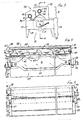
- FIGURE 2 is an isometric view of a lamp-reflector assembly of the apparatus of Figure 1.
- FIGURE 3 is an end view of the lamp reflector assembly of Figure 2.
- FIGURE 4 is a cross-section taken through the line 4-4 of Figure 3 looking in the direction of the arrows 4-4.
- FIGURE 5 is a plan view of the lamp reflector assembly of Figure 2.
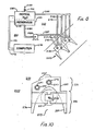
- FIGURE 6 is an enlarged fragmentary view of Figure 1 showing the system of the invention in greater detail, including the air, water, refrigerating and computer control apparatus.
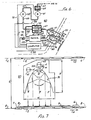
- FIGURE 7 is an enlarged schematic view, similar to figure 3, showing the limited space in which the lamp-reflector assembly of the system of the invention can be installed and the manner in which ultraviolet rays are reflected by the lamp-reflector assembly of the system of this invention.
- FIGURE 8 is a schematic view of a portion of the delivery section of the end of a multi-stand, multi-color, sheet-fed printing press through which a coated substrate is passed for the purpose of drying the coating by means of another embodiment of the system and method of this invention.
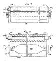
- FIGURE 9 is a plan view of the Lamp relflctor assembly of the embodiment of the apparatus shown in Figure 8.
- FIGURE 10 is an end view of the lamp reflector assembly of Figure 9.
- FIGURE 11 is a cross-section taken through the Line 11-11 of Figure 9, looking in the direction of the arrows 11-11.
- Referring to Figure 1 there is shown the
delivery section 1 at the end of a multi-stand, multi-color, sheet-fed printing press, not shown, capable of handling coated sheets having a width of approximately 40 inches at a speed of between about 300 to 550 feet per minute.Feed chain 2, shown in greater detail in Figure 7, moves from the multi-stand section of the press, not shown, in the direction of arrow A along bottom passline B. Chain 2 continues along the bottom pass line B, upwardly and over guide roller 3 around drive sprocket 4, where it reverses directiion.Chain 2 then travels along upper pass line C, over sprocket 5 and downwardly and fromdelivery section 1 in the direction of arrow D and returns to the multi-stand section of the press. - Spaced along
chain 2 are a plurality of releasable clamps 6 that engage the leading edges ofsheets 7 which rest onchain 2. On theupper surface 8 of eachsheet 7 is a thin coating 9 of ink or chemical that has been placed onsurface 8 during the passage ofsheets 7 through the multi-stand section of the press. After eachsheet 7 passes over guide roller 3, clamps 6 which engage the leading edge of the sheet release, and it drop through delivery section opening 10 onto the top of a stack 11 ofsheets 7 from where they can be moved subsequently to a desired location. Exhaust blower 12 continuously removes hot air from the interior ofdelivery section 1. - As
sheets 7 resting onfeed chain 2 travel throughdelivery section 1 along bottom pass lane B, they move beneath one or more ultraviolet lamp-reflector assemblies 20, two as shown in Figure 1. As best shown in Figures 2 through 5, eachlamp assembly 20 includes elongated tubular, medium-pressure mercuryvapor ultraviolet lamp 21, a line source of light, having acentral portion 22 in which there is formed an arc, shown in Figure 7, that emits radiation, andend portions Wires portions lamp 21 are connected to a suitable power source, not shown, for energizinglamp 21.Lamp end portions refractory insulators block 30. - As shown in Figure 2, reflector-
block 30, which is made of extruded aluminum, has anupper portion 31 and alower portion 32 and acavity 33 in the shape of a parabolic trough having areflective surface 34. As shown in Figures 2-5, reflector-block 30 has a top 35,side 36, steppedside 37 and ends 38 and 39. At the apex ofreflective surface 34 ischannel 40 that extends longitudinally ofblock 30 fromend 38 to end 39. Extending longitudinally ofblock 30, fromend 38 to end 39, arewater conduit 41 andair conduit 42.Water conduit 41 is positioned in theupper portion 31 ofblock 30, betweenreflective surface 34 and block top 35 andside 36.Air conduit 42 is positioned in theupper portion 31 ofblock 30, betweenchannel 40 and top 35. A plurality of longitudinally extendingports 43, separated bynarrow ribs 44, connectchannel 40 withconduit 42. - As shown in Figures 2, 4 and 5, connected to
water conduit 41 at reflector-block end 38 iswater inlet tubing 45, and at reflector-block end 39 iswater discharge tubing 46. Connected toair conduit 42 at reflector-block end 38 isair inlet tubing 47.Air conduit 42 is closed byplug 48 at reflector-block end 39. As shown in Figures 3-5, secured to blockreflective surface 34, a distance of about 1 inch fromchannel 40 and spaced about 4 inches fromblock end 38 istemperature sensing device 49, such as a thermocouple or thermistor, from whichwires 50 extend. - As best shown in Figure 6, cool, i.e. refrigerated, air and water is supplied to lamp-
reflector assemblies 20 by means of air-water system 60.System 60 includes intermediate pressure blowers 61 and 62, which are connected in series,heat exchanger 70, refrigeratingdevice 80 andcomputer control device 90. Air is supplied to blower 61 throughair inlet tubing 63 andair filter 64. In blower 61 the air is pressurized and its temperature elevated somewhat before being discharged through connectingtube 65 to blower 62 where the air is further pressurized and its temperature again elevated. The pressurized, heated air then passes through tube 66 to and through a first side of shell andtube heat exchanger 70 where the pressurized air is cooled as hereinafter described. As shown in Figure 4, the cooled pressurized air then passes through cooledair discharge line 67 toair inlet tubing 47 and toair conduit 42 of eachlamp assembly 20. The cooled, pressurized air passes intoair conduit 42 and discharges throughports 43 and reflector-block channel 40, at between about 1/4 to 1/2 cfm. per linear inch of length, as shown in Figure 4 by arrows E, over and aroundlamp 21 to uniformly cool it and maintain its temperature within a prescribed operating range, i.e. between about 1100o F to 1500o F. - As shown in Figure 6, the pressurized heated air passing through one side of
heat exchanger 70 has its temperature lowered by coolant that circulates from refrigeratingdevice 80 throughcoolant tube 81 to a second side ofheat exchanger 70 where the coolant extracts heat from the pressurized air in the first side thereof. The coolant at a higher temperature exitsheat exchanger 70 and returns throughcoolant tube 82 to refrigeratingdevice 80 where the temperature of the coolant is lowered in a manner wall known to those skilled in the art. - As shown in Figures 2, 5 and 6, each reflector-
block 30 is also cooled by water circulated in a closed loop through refrigeratingdevice 80, water feed tube 102 andwater inlet tubing 45,water conduit 41 andwater discharge tubing 46 of each such block back to refrigeratingdevice 80. Circulation is accomplished bywater pump 46A connected todischarge tube 46. Water is initially provided to the closed loop throughwater supply tube 100, from a source not shown, which connects to refrigeratingdevice 80 and water feed tube 102 therein but not shown. Any replenishment of water is provided in the same manner. The cooled water passing throughwater conduit 41 of eachreflector block 30 acts to maintain its temperature within a prescribed operating range of between about 50o F. to 80o F., preferably about 65o F. In passing through reflector-block 30, the water temperature rises and it returns throughwater discharge tubing 46 and pump 46A to refrigeratingdevice 80 where the water is recooled. - In another variation of the invention the objectives are accomplished by a method of operating the above described system in the following manner.
- At the time of starting a multi-stand press ahead of
delivery section 1, pump 46A operates to circulate water through reflector-block 30 to bring it within preference temperature of between about 45o F. to 75o F., preferably about 50o F.Temperature sensing device 49, connected tocomputer control device 90, continually monitors the temperature within the vicinity of its position adjacent blockreflective surface 34 andlamp 21, and when that temperature exceeds 75o F.computer control device 90 throughline 93starts refrigerating device 80 to cool the water circulating throughdevice 80. - When desired the press operator strikes
lamp 21, i.e. turns on the power, initiating an arc within itscentral portion 22, andlamp 21 reaches full power in about 2 minutes. As the lamp continues operation and grows hotter the temperature in the vicinity thereof and adjacent reflector-block 40 rises and the continually rising temperatures are communicated bytemperature sensing device 49 tocomputer control device 90. When the temperature reaches between 140o F. to 160o F.,computer control device 90 through line 91 starts intermediate pressure blower 61 which draws air throughair inlet tube 63 andfilter 64 and compresses it to a pressure of between about 1/2 psi. to 1 psi. and increases the temperature thereof. For example, if the air to blower 61 has an ambient temperature of about 70o F., the temperature of the pressurized air increases to about 90o F. Pressurized air fromblower 1 circulates through the appropriate tubing through intermediate pressure blower 62, which is inactive,heat exchanger 70, which is also inactive, to reflector-block 30 where the air passes intoair conduit 42 and is discharged throughports 43 andchannel 40 overlamp 21 andreflective surface 34 of such block. - Even as the pressurized air from blower 61 is discharged over
lamp 21, its operating temperature continues to increase, as do the temperatures monitored by sensingdevice 49. When the temperature communicated tocomputer control device 90 by sensingdevice 49 rises to between about 450o F. to 550o F.,control device 90 throughline 92 starts intermediate pressure blower 62 connected in series with blower 61. Blower 62 throughtube 65 receives pressurized heated air from blower 61 and further compresses it to a pressure between about 1.5 psi. to 1.75 psi., further increasing its temperature. The further pressurized and hotter air circulates throughheat exchanger 70, which remains inactive, and to reflector-block 30 in the manner described in the preceding paragraph. The air discharged from blower 62 has a temperature of between about 90o F. to 130o F., preferably about 110o F. - When the temperature communicated by
temperature sensing device 49 tocomputer control device 90 rises to between about 650o F. to 750o F.,control device 90, throughline 93starts refrigerating device 80 which circulates coolant throughline 81,heat exchanger 70 andcoolant return tube 82 back todevice 80. The heated and pressurized air passing through a first side ofheat exchanger 70 is cooled by the passage of coolant from refrigeratingdevice 81 circulated through the second side ofheat exchanger 70 in a manner to decrease the temperature of the pressurized air between about 30o F. to 50o F. The heated, pressurized air passing throughheat exchanger 70 is cooled to a temperature between about 50o F. to 80o F., preferably about 60o F. and passes to and from reflector-block 30 throughchannel 40 and over the surface oflamp 21 and blockreflective surface 34 to cool those elements. - The preferred embodiment of the system described above and its method of operation is used in conjunction with a press that is programmed to operate at four different stages of power, i.e. 1/4, 1/2, 3/4 or full power and
computer control device 90, responding to temperatures communicated to it fromtemperature sensing device 49, functions to activate blower 61, blower 62, refrigeratingdevice 80 andheat exchanger 70 in the manner described above. Other dryer systems incorporated in commercial presses do not operate in the 4-stage manner described above and operate only at 1/2 or full power. At startup of such other presses the cooling air blower is started at approximately the same time that the lamp arc is struck, and the air, at times, tends to over-cool the lamp and cause the arc to extinguish. Because of such early cooling present commercially available ultraviolet systems require between about 3 to 5 minutes for the ultraviolet lamp to reach full power. - In the delivery sections of commercial sheet-fed presses space is limited and the distance small between the bottom and upper pass lines of the chain normally used for transporting the printed sheets through the presses. Consequently, in presses currently in service, any equipment to be retrofitted into such sections must be small and function well enough to do its job. If large equipment is used, the pass lines of the chain must be spread, which involves a major and costly modification of the delivery section. In addition, the commercial pressure to operate presses at higher speeds sometimes can be satisfied only by placing additional drying equipment between the stands of a multi-stand press, locations where space is also at a premium.
- In Figure 7 is illustrated a manner in which the
lamp reflector assembly 20 of the preferred system described above may be installed between the bottom pass line B and the upper pass line C ofchain 2. In many presses the distance L between such pass lines may be only between about 3 inches to 6 inches. By virtue of the air and water cooling of the lamp-reflector assembly 20 it can be manufactured with an overall height H of between about 2-3/4 inches to 3-1/4 inches, with a width W of between about 2 inches to 3-1/2 inches. In a lamp-reflector assembly 20 with such dimensions,channel 40 may have a width w between about 3/64 inch to 9/64 inch, preferably about 1/16 inch, andwater conduit 41 andair conduit 42 each may have a diameter d between about 3/8 inch to 3/4 inch. The diameter oflamp 21 may be between about 3/4 inch to 1-3/16 inches. The length oflamp 21 governs the length of reflector-block 30,channel 40 andports 43. It is important thatchannel 40 have a length at least equal to thecentral portion 22 oflamp 21 to ensure adequate cooling of the central portion. Preferably elongatedchannel 40 should be at least as long as the overall length oflamp 21, i.e. includinglamp end 23,central portion 22 and end 24 to ensure that the ends of the lamp receive adequate cooling. One of the advantages of theelongated channel 40 is that the pressurized air passing therefrom flows over and aroundlamp 21 to cool the surface thereof in a uniform manner. The arrows F in Figure 7 illustrate the manner in which rays reflect in a parallel manner from parabolic troughreflective surface 34. - Blowers 61 and 62 have been identified as intermediate pressure blowers. An intermediate pressure blower is one that operates at a pressure of about 1/2 to 4 psi. with an output of between about 50 to 420 cfm. One blower meeting such requirements is a regenerative blower made by Gast Manufacturing Corp. of Benton Harbor, Michigan. This blower has blades only at the periphery of the impeller and as the blower impeller rotates, centrifugal force moves air from the root of the blade to the blade tip. Upon leaving the blade tip the air flows around the impeller housing contour back to the root of the succeeding blade where the flow pattern is repeated. This action provides a quasi-staging effect to increase pressure differential capability. In the preferred embodiment described above
computer control device 90 is an open board computer manufactured by Analog Device, Inc. of Norwood, Massachusetts. Refrigeratingdevice 80 includes a condensing unit manufactured by Copeland Corporation of Sidney, Ohio.Heat exchanger 70 is a shell and tube heat exchanger manufactured by Trantor Division of ITT Corporation. - Reflector-
block 30 of extruded aluminum which provides adequate strength to support an ultraviolet lamp, which has a length of up to 60 inches and operates at a temperature of about 1100o F., without sagging and damaging the lamp. While the preferred embodiment of reflector-block 30 includes a plurality ofports 43 separated byribs 44, there can be one single port having a length approximately equal to that ofchannel 40.Ribs 44 strengthen and provide rigidity forreflector block 30 and prevent it from sagging and deteriorating under the high oerating conditions oflamp 21. - In certain presses operating under particularly difficult conditions, it is desirable to have a curing system that is substantially completely cooled by refrigerated water. It is also desirable to have a system in which the radiation striking the coated substrate is substantially the same as the radiation from the originating source, i.e. from the lamp and reflective surface of the reflector-block assembly. Such a system shall be referred to as one having a "uniform refractive index". Putting it another way, it is desirable to have a substantially completely water cooled system which avoids the use of one or more filters between the reflector-block assembLy and the coated substrate. Such filters tend to build-up heat in a system and/or create an uneven dispersion of radiation at the substrate, which tends to have a higher heat gradient at discrete points. Both such conditions contribute to curing and/or operating problems. The embodiment of such a substantially completely water cooled system is shown in Figure 8 wherein there are shown two ultraviolet
lamp reflector assemblies 220 positioned in the delivery section, not shown, at the end of a multi-stand, multi-color, sheet-fed printing press, not shown, as described above; refrigeratingdevice 280 andreservoir 281; closedwater circulation system 260 andcontrol system 300. - As best shown in Figure 9, 10, and 11, each
lamp assembly 220 includes elongated tubular, medium-pressure mercury vaporultraviolet lamp 221, a line source of light, having acentral portion 222 and end portions 223 and 224. Lines 225 and 226 of end portions 223 and 224, respectively, oflamp 221 are connected to a suitable power source, not shown, for energizinglamp 221. Lamp end portions 223 and 224 are mounted in refractory insulators 227 and 228, respectively, secured in opposite ends ofelongated reflector block 230.Reflector block 230, which is a monolithic extruded aluminum member, has anupper portion 231, alower portion 232 and a cavity 233, which is in the shape of a parabolic trough that has a smoothreflective surface 234.Block 230 has a top 235,side 236, steppedside 237 and ends 238 and 239. Extending longitudinally ofblock 230 fromend 238 to end 239 are spacedwater conduits Water conduits upper portion 231 ofblock 230, between cavityreflective surface 234 and block top 235 and betweenside 236 and steppedside 237.Lamp 221 is mounted fully within cavity 233 for proper focusing of the light rays, for shielding the coated sheet and surrounding environment from stray light and heat and to protect the lamp from being struck and damaged accidentally. - As shown in Figures 8, 9 and 11, connected to
water conduits block end 238 arewater inlet tubes block end 239 arewater discharge tubes - Figure 8, shows a closed system for supplying refrigerated water to
lamp reflector assembly 220. Water is circulated throughwater circulation system 260 in a closed loop through refrigeratingdevice 280, connectingwater reservoir 281, pumpwater supply tube 282, pump 283, pumpwater discharge tube 284,water inlet tubes conduits reflector block 230. Fromreflector block end 239, water fromconduits water discharge tubes device 280. Water, as required, is fed from a source, not shown, to refrigeratingdevice 280 throughfeed line 200 equipped with a shut-offvalve 201. - A curing system which includes the embodiment of the invention using a reflector block substantially completely cooled by refrigerated water may be controlled in a manner similar to that described above for an air-water system, i.e. with a computer control system including a temperature sensing device mounted within reflector block cavity 233, However, as shown in Figure 8, a
preferred control system 300 includes within water reservoir 281 atemperature measuring device 249 which is connected byline 291 to computer 290 that is connected to refrigeratingdevice 280 byline 292.Temperature measuring device 249 monitors the temperature of the water withinreservoir 281 and communicates an applicable signal throughline 291 to computer 290. When the temperature of the water withinreservoir 281 is not within a preferred range of 45oF. to 75oF., the computer 290, throughline 291,signals refrigerating device 280 to start or shut off as conditions require. Computer 290 may be programmed to start refrigeratingdevice 280 to lower the temperature of, or recool, the water when the temparature of the water withinreservoir 281 is about 60oF. so that the temperature of the water withinwater circulation system 260, preferably, does not exceed above 75oF. at any time. When the refrigerated cooling water fed to reflector block 230 is within the preferred temperature range of 45oF. to 75oF.,reflector block 230 operates within a range between about 50oF. to 90oF., depending upon various environmental factors, a very desirable operating temperature. - The refrigerated water passing through
water inlet conduits conduits block end 238 is about 20 to 30 psi, and the flow of water through such conduits is maintained at between about 0.75 to 1.25 gallons per minute for a reflector block about 40 inches long and 0.75 to 2.25 gallons per minute for a reflector block about 70 inches long. Preferably pump 283 is a turbine-type pump having a discharge pressure of about 90 psi or a positive displacement pump with similar characteristics. - The unique feature of the reflector blocks of the embodiments of the systems of this invention, i.e. reflector blocks 30 and 230, is that all surfaces are generally smooth, i.e. generally flat, as are the flat outer surfaces, or curved, as are the block cavities. As used herein "generally smooth" means without surface enhancements, such as ribs or fins, which meaningfully increase surface area in such a way to convect heat to the surrounding environment. Use of fins or ribs on reflector blocks is the usual way of improving the cooling of such blocks by increasing surface area in much the same manner as do fins on the coil or tube of a conventional room hot water system. However, cooling reflector blocks by means of fins or ribs causes heat to dissipates to the surrounding environment which, in the case of printing press curing equipment, may create serious operating problems. By using a reflector block with generally smooth surfaces and using only refrigerated water from a closed loop system for cooling purposes, heat from the ultraviolet lamp is concentrated in the reflector block. The block acts as a heat sink and the cooling water absorbs the heat and carries it away from both the reflector block and surrounding equipment in a manner to contribute to improved operation. The substantially completely water cooled reflector block is of a size comparable to that of the air-water cooled block of the preferred embodiment.
-
Water conduits water reflector block 230 have a diameter between about 3/8 inch to 3/4 inch, For a variety of reasons,conduits - The term "refrigerated water" or liquid as used herein means water that is artificially cooled to a temperature of between about 45o F. to 75o F. regardless of ambient temperature. Such cooling can be artifically accomplished in a closed loop system including a heat exchanger wherein liquid is cooled by a refrigerating device, liquid nitrogen, ice, etc.
- The term "substantially completely cooled by water" as used herein means that the reflector block of the system is cooled to a temperature of between about 50oF. to 90oF. by the sole use of refrigerated water circulated through one or more conduits of the block. No other air cooling is required and, if used, may require the use of additional equipment and/or possibly contribute to operating problems.
-
Pumps - By use of the above embodiment of the invention having a reflector block which is substantially completely cured by refrigerated water within a preferred temperature range of between about 45oF. to 75oF., the wattage per inch for
lamp 221 can be increased significantly. Increasing the lamp wattage produces a commensurate increase in curing speed for the coating on a moving substrate. For example, in prior art cooling systems the lamps are 200 to 300 watts per inch which produced a curing speed of approximately 200 feet per minute for a substrate coated with a clear ultraviolet varnish about 1/2 mill thick, as an example one of many ultraviolet varnishes made by Pierce and Stevens Company. By comparison in a system using a reflector block which is substantially completely cured by refrigerated water and without air cooling and/or use of a filter, a more power intensive lamp of about 400 to 450 watts per inch can be used for curing an identical ultraviolet varnish about 1/2 mill thick on a substrate moving at a speed as high as about 300 to 350 feet per minute, more than a 50% improvement in speed. Under normal circumstances the power to cure speed ratio may be increased by from about 15% to 40% a substantial improvement in operating efficiency, with commensurate reduction in operating costs. - While the system of this invention and its method of operation have been described above in a preferred manner and second embodiment, the description has been simplified by avoiding reference to detailed piping, valving and controls that are inherent in any such system and well known to those skilled in the art. It is also recognized that
reflective surfaces
Claims (16)
(a) an elongated reflector block (30; 230) having:
(i) a cavity (33; 233) having a reflective surface (34; 234), and
(ii)a conduit (42; 242) extending through said block,
(b) an elongated ultraviolet lamp (21; 221) having a central portion (22; 222) within said reflector block cavity;
(a) pump means (46A; 283), and
(b) tubing means (100, 102, 45, 46; 282, 284, 245, 246, 247, 248, 289)
(a) temperature monitoring means (49; 249) for monitoring the temperature of said cooling liquid circulated through said closed loop system, and
(b) control means (90; 290) connected with said temperature monitoring means and said refrigerating means for receiving signals from said temperature monitoring means and signaling said refrigerating means when the signals from said temperature monitoring means indicate that the cooled liquid circulating through said closed loop system has deviated from an established temperature range.
(a) a monolithic aluminum extrusion elongated reflector block (30; 230) having:
(i) a generally smooth outer surface,
(ii) a cavity (33; 233) with a parabolic trough reflective surface (34; 234), and
(iii) at least one conduit (42; 242) extending longitudinally thereof;
(b) an elongated ultraviolet lamp (21; 221) having a central portion (22; 222) within said reflector block cavity;
(i) pump means (46A; 283), and
(ii) tubing means (100, 102, 45, 46; 282, 284, 245, 246, 247, 248, 289);
(a) temperature monitoring means (49; 249) for monitoring the temperature of said cooling liquid circulated through said closed loop system; and
(b) control means (90; 290) connected with said temperature monitoring means and said refrigerating means for receiving signals from said temperature monitoring means and signaling said refrigerating means when the signals from said temperature monitoring means indicate that the cooled liquid circulating through said closed loop system has deviated from an established temperature range.
(a) an elongated reflector block (30; 230) having:
(i) a cavity (33; 233) having a reflective surface, and
(ii) a conduit (42; 242) extending through said block,
(b) an elongated ultraviolet lamp (21; 221) having a central portion within said reflector block cavity;
(a) pump means (46A; 283), and
(b) tubing means (100, 102, 45, 46; 282, 284, 245, 246, 247, 248, 289)
(a) temperature monitoring means (49; 249) for monitoring the temperature of said cooling liquid circulated through said closed loop system, and
(b) control means (90; 290) connected with said temperature monitoring means and said refrigerating means for receiving signals from said temperature monitoring means and signaling said refrigerating means when the signals from said temperature monitoring means indicate that the cooled liquid circulating through said closed loop system has deviated from an established temperature range.
(a) a monolithic aluminum extrusion elongated reflector block (30; 230) having:
(i) a generally smooth outer surface,
(ii) a cavity (33; 233) with a parabolic trough reflective surface, and
(iii) at least one conduit (42; 242) extending longitudinally thereof; (b) an elongated ultraviolet lamp (21; 221) having a central portion (22; 222) within said reflector block cavity;
(i) pump means (46A; 283), and
(ii) tubing means (100, 102, 45, 46; 282, 284, 245, 246, 247, 248,289 );
(a) temperature monitoring means (49; 249) for monitoring the temperature of said cooling liquid circulated through said closed loop system; and
(b) control means (90; 290) connected with said temperature monitoring means and said refrigerating means for receiving signals from said temperature monitoring means and signaling said refrigerating means when the signals from said temperature monitoring means indicate that the cooled liquid circulating through said closed loop system has deviated from an established temperature range.
(a) said refrigerating means,
(b) pump means (46A; 283), and
(c) tubing means (100, 102, 45, 46; 282, 284, 245, 246, 247, 248, 289)
(a) means for monitoring (49; 249) the temperature of the cooled circulating liquid, and
(b) control means (90; 290) connected with said temperature means and said refrigerating means.
(a) said refrigerating means,
(b) pump means (46A; 283), and
(c) tubing means (100, 102, 45, 46; 282, 284, 245, 246, 247, 248, 289);
(a) means for monitoring (49; 249) the temperature of the circulating liquid, and
(b) control means (90; 290) connected with said temperature monitoring means and said refrigerating means.
(a) said refrigerating means,
(b) pump means (46A; 283), and
(c) tubing means (100, 102, 45, 46; 282, 284, 245, 246, 247, 248, 289);
(a) means for monitoring (49; 249) the temperature of the cooled circulating liquid, and
(b) control means (90; 290) connected with said temperature means and said refrigerating means.
(a) said refrigerating means,
(b) pump means (46A; 283),
(c) tubing means (100, 102, 45, 46; 282, 284, 245, 246, 247, 248, 289);
(a) means for monitoring (49; 249) the temperature of the circulating liquid, and
(b) control means (90; 290) connected with said temperature monitoring means and said refrigerating means.
Applications Claiming Priority (4)
| Application Number | Priority Date | Filing Date | Title |
|---|---|---|---|
| US07/272,763 US5003185A (en) | 1988-11-17 | 1988-11-17 | System and method for photochemically curing a coating on a substrate |
| US431122 | 1989-11-07 | ||
| US07/431,122 US4983852A (en) | 1988-11-17 | 1989-11-07 | System and method for photochemically curing a coating on a substrate |
| US272763 | 2002-10-17 |
Publications (3)
| Publication Number | Publication Date |
|---|---|
| EP0370352A2 true EP0370352A2 (en) | 1990-05-30 |
| EP0370352A3 EP0370352A3 (en) | 1991-03-20 |
| EP0370352B1 EP0370352B1 (en) | 1995-09-13 |
Family
ID=26955725
Family Applications (1)
| Application Number | Title | Priority Date | Filing Date |
|---|---|---|---|
| EP89120983A Revoked EP0370352B1 (en) | 1988-11-17 | 1989-11-11 | An apparatus for curing a coating on a moving substrate and a method of operating the apparatus |
Country Status (6)
| Country | Link |
|---|---|
| US (1) | US4983852A (en) |
| EP (1) | EP0370352B1 (en) |
| JP (1) | JPH02219652A (en) |
| CA (1) | CA2002781C (en) |
| DE (1) | DE68924242T2 (en) |
| ES (1) | ES2078232T3 (en) |
Cited By (2)
| Publication number | Priority date | Publication date | Assignee | Title |
|---|---|---|---|---|
| WO2002084190A1 (en) * | 2001-04-18 | 2002-10-24 | Advanced Photonics Technologies Ag | Radiator module and high speed radiation system |
| EP1426182A1 (en) * | 2002-12-06 | 2004-06-09 | MAN Roland Druckmaschinen AG | Excimer radiator for the drier of a printing press |
Families Citing this family (11)
| Publication number | Priority date | Publication date | Assignee | Title |
|---|---|---|---|---|
| RU2070211C1 (en) * | 1990-09-27 | 1996-12-10 | Сам Янг Ко., Лтд. | Process for preparing hydrophilic polymeric film and device for carrying it into effect |
| JPH08174567A (en) * | 1994-10-25 | 1996-07-09 | Ushio Inc | Light irradiator |
| US5832833A (en) * | 1995-07-25 | 1998-11-10 | Burgio; Joseph Thomas | Apparatus and method for drying a substrate printed on a multi-stand offset press |
| US5727472A (en) * | 1995-07-25 | 1998-03-17 | Burgio; Joseph Thomas | Apparatus and method for drying sheets printed on a multi-stand press |
| EP1227934B1 (en) * | 1999-10-29 | 2008-01-02 | Daniel Bostrack | Print cylinder cooling system |
| US6755518B2 (en) * | 2001-08-30 | 2004-06-29 | L&P Property Management Company | Method and apparatus for ink jet printing on rigid panels |
| ATE337520T1 (en) | 2001-06-13 | 2006-09-15 | Joseph T Burgio | DEVICE FOR LIMITED THERMAL CURING OF LIGHT-SENSITIVE COATINGS AND INKS |
| US20070295012A1 (en) * | 2006-06-26 | 2007-12-27 | Applied Materials, Inc. | Nitrogen enriched cooling air module for uv curing system |
| US20070298167A1 (en) * | 2006-06-26 | 2007-12-27 | Applied Materials, Inc. | Ozone abatement in a re-circulating cooling system |
| US8517750B2 (en) * | 2009-08-27 | 2013-08-27 | Air Motion Systems, Inc | Interchangeable UV LED curing system |
| DE102018206154B4 (en) * | 2018-04-20 | 2021-10-28 | Koenig & Bauer Ag | Drying device for a printing material processing machine and method for operating a drying device |
Family Cites Families (12)
| Publication number | Priority date | Publication date | Assignee | Title |
|---|---|---|---|---|
| US3026435A (en) * | 1960-09-16 | 1962-03-20 | Mcpherson Instr Corp | Ultraviolet lamp |
| US3887813A (en) * | 1967-06-26 | 1975-06-03 | Instrumentation Specialties Co | Short wavelength fluorescent light source |
| CH577060B5 (en) * | 1972-10-18 | 1976-06-30 | Ciba Geigy Ag | |
| US4000407A (en) * | 1975-04-07 | 1976-12-28 | Illumination Industries Inc. | Combined infrared filter and light focusing apparatus for a mercury vapor lamp |
| US4005135A (en) * | 1975-04-07 | 1977-01-25 | Sun Chemical Corporation | Rotatable ultraviolet lamp reflector and heat sink |
| GB1515086A (en) * | 1975-05-22 | 1978-06-21 | Sun Chemical Corp | Ultraviolet lamp assembly |
| US4019062A (en) * | 1975-09-11 | 1977-04-19 | Rongren Eric H | Unit for treatment of substrate with ultraviolet radiation |
| US4048916A (en) * | 1975-09-26 | 1977-09-20 | Sun Chemical Corporation | Curing section for continuous motion decorator |
| AU2935384A (en) * | 1983-06-24 | 1985-01-03 | Screen Printing Supplies Pty. Ltd. | Heat curing apparatus |
| JPS61131849A (en) * | 1984-11-29 | 1986-06-19 | Asahi Kogyosha:Kk | Cooling water circulation device |
| DE3526082A1 (en) * | 1985-07-20 | 1987-01-29 | Rueesch Ferd Ag | DEVICE FOR DRYING UV PRINTING INKS |
| US4798960A (en) * | 1986-07-17 | 1989-01-17 | Ferd. Ruesch Ag | Device for the treatment of substances by UV radiation |
-
1989
- 1989-11-07 US US07/431,122 patent/US4983852A/en not_active Expired - Lifetime
- 1989-11-10 CA CA002002781A patent/CA2002781C/en not_active Expired - Lifetime
- 1989-11-11 ES ES89120983T patent/ES2078232T3/en not_active Expired - Lifetime
- 1989-11-11 DE DE68924242T patent/DE68924242T2/en not_active Revoked
- 1989-11-11 EP EP89120983A patent/EP0370352B1/en not_active Revoked
- 1989-11-13 JP JP1292545A patent/JPH02219652A/en active Pending
Cited By (2)
| Publication number | Priority date | Publication date | Assignee | Title |
|---|---|---|---|---|
| WO2002084190A1 (en) * | 2001-04-18 | 2002-10-24 | Advanced Photonics Technologies Ag | Radiator module and high speed radiation system |
| EP1426182A1 (en) * | 2002-12-06 | 2004-06-09 | MAN Roland Druckmaschinen AG | Excimer radiator for the drier of a printing press |
Also Published As
| Publication number | Publication date |
|---|---|
| DE68924242D1 (en) | 1995-10-19 |
| EP0370352A3 (en) | 1991-03-20 |
| ES2078232T3 (en) | 1995-12-16 |
| EP0370352B1 (en) | 1995-09-13 |
| JPH02219652A (en) | 1990-09-03 |
| DE68924242T2 (en) | 1996-02-22 |
| CA2002781A1 (en) | 1990-05-11 |
| US4983852A (en) | 1991-01-08 |
| CA2002781C (en) | 1995-10-24 |
Similar Documents
| Publication | Publication Date | Title |
|---|---|---|
| US5003185A (en) | System and method for photochemically curing a coating on a substrate | |
| US4983852A (en) | System and method for photochemically curing a coating on a substrate | |
| US4811493A (en) | Dryer-cooler apparatus | |
| US9746235B2 (en) | Infrared float bar | |
| US6807906B1 (en) | Zoned ultraviolet curing system for printing press | |
| US6619819B2 (en) | Lamp assembly | |
| US4143278A (en) | Radiation cure reactor | |
| GB2360084A (en) | Shuttered ultra-violet/ infra-red lamp | |
| EP0146998A1 (en) | Curing apparatus | |
| US7669530B2 (en) | UV curing assembly having sheet transfer unit with heat sink vacuum plate | |
| US5668921A (en) | Hot-air dryer with infrared heater and slit-shaped outlet | |
| JP2001079388A (en) | UV irradiation device | |
| EP2089228A1 (en) | Cooling system for ink curing apparatus | |
| SU1060251A1 (en) | Apparatus for photographic hardening of paint and varnish coatings on articles | |
| KR200184471Y1 (en) | Reflection plate of ultraviolet drier | |
| KR200219009Y1 (en) | Hot-air heating system | |
| SU1133463A1 (en) | Aerodynamic drying unit | |
| JPH03108544A (en) | Cooling system |
Legal Events
| Date | Code | Title | Description |
|---|---|---|---|
| PUAI | Public reference made under article 153(3) epc to a published international application that has entered the european phase |
Free format text: ORIGINAL CODE: 0009012 |
|
| AK | Designated contracting states |
Kind code of ref document: A2 Designated state(s): BE CH DE ES FR GB IT LI NL SE |
|
| PUAL | Search report despatched |
Free format text: ORIGINAL CODE: 0009013 |
|
| AK | Designated contracting states |
Kind code of ref document: A3 Designated state(s): BE CH DE ES FR GB IT LI NL SE |
|
| 17P | Request for examination filed |
Effective date: 19910903 |
|
| 17Q | First examination report despatched |
Effective date: 19930423 |
|
| GRAA | (expected) grant |
Free format text: ORIGINAL CODE: 0009210 |
|
| AK | Designated contracting states |
Kind code of ref document: B1 Designated state(s): BE CH DE ES FR GB IT LI NL SE |
|
| REF | Corresponds to: |
Ref document number: 68924242 Country of ref document: DE Date of ref document: 19951019 |
|
| ITF | It: translation for a ep patent filed | ||
| REG | Reference to a national code |
Ref country code: ES Ref legal event code: FG2A Ref document number: 2078232 Country of ref document: ES Kind code of ref document: T3 |
|
| ET | Fr: translation filed | ||
| PLBQ | Unpublished change to opponent data |
Free format text: ORIGINAL CODE: EPIDOS OPPO |
|
| PLBI | Opposition filed |
Free format text: ORIGINAL CODE: 0009260 |
|
| PLBF | Reply of patent proprietor to notice(s) of opposition |
Free format text: ORIGINAL CODE: EPIDOS OBSO |
|
| 26 | Opposition filed |
Opponent name: NORDSON CORPORATION Effective date: 19960612 |
|
| NLR1 | Nl: opposition has been filed with the epo |
Opponent name: NORDSON CORPORATION |
|
| PLBF | Reply of patent proprietor to notice(s) of opposition |
Free format text: ORIGINAL CODE: EPIDOS OBSO |
|
| PLBF | Reply of patent proprietor to notice(s) of opposition |
Free format text: ORIGINAL CODE: EPIDOS OBSO |
|
| PGFP | Annual fee paid to national office [announced via postgrant information from national office to epo] |
Ref country code: DE Payment date: 19980728 Year of fee payment: 10 |
|
| PGFP | Annual fee paid to national office [announced via postgrant information from national office to epo] |
Ref country code: FR Payment date: 19981116 Year of fee payment: 10 |
|
| PGFP | Annual fee paid to national office [announced via postgrant information from national office to epo] |
Ref country code: SE Payment date: 19981119 Year of fee payment: 10 Ref country code: BE Payment date: 19981119 Year of fee payment: 10 |
|
| PGFP | Annual fee paid to national office [announced via postgrant information from national office to epo] |
Ref country code: GB Payment date: 19981124 Year of fee payment: 10 Ref country code: ES Payment date: 19981124 Year of fee payment: 10 |
|
| PGFP | Annual fee paid to national office [announced via postgrant information from national office to epo] |
Ref country code: NL Payment date: 19981125 Year of fee payment: 10 |
|
| PGFP | Annual fee paid to national office [announced via postgrant information from national office to epo] |
Ref country code: CH Payment date: 19981126 Year of fee payment: 10 |
|
| RDAH | Patent revoked |
Free format text: ORIGINAL CODE: EPIDOS REVO |
|
| RDAG | Patent revoked |
Free format text: ORIGINAL CODE: 0009271 |
|
| STAA | Information on the status of an ep patent application or granted ep patent |
Free format text: STATUS: PATENT REVOKED |
|
| REG | Reference to a national code |
Ref country code: CH Ref legal event code: PL |
|
| 27W | Patent revoked |
Effective date: 19981113 |
|
| GBPR | Gb: patent revoked under art. 102 of the ep convention designating the uk as contracting state |
Free format text: 981113 |
|
| NLR2 | Nl: decision of opposition |