EP0370384A2 - Lösbare Verbindung eines Hochstromkabels mit einem sammelschieneartigen Anschlussschwert über eine Kontakttasche - Google Patents
Lösbare Verbindung eines Hochstromkabels mit einem sammelschieneartigen Anschlussschwert über eine Kontakttasche Download PDFInfo
- Publication number
- EP0370384A2 EP0370384A2 EP89121201A EP89121201A EP0370384A2 EP 0370384 A2 EP0370384 A2 EP 0370384A2 EP 89121201 A EP89121201 A EP 89121201A EP 89121201 A EP89121201 A EP 89121201A EP 0370384 A2 EP0370384 A2 EP 0370384A2
- Authority
- EP
- European Patent Office
- Prior art keywords
- contact
- current cable
- cable
- connection
- receptacle
- Prior art date
- Legal status (The legal status is an assumption and is not a legal conclusion. Google has not performed a legal analysis and makes no representation as to the accuracy of the status listed.)
- Granted
Links
- 239000007787 solid Substances 0.000 claims abstract description 7
- IHQKEDIOMGYHEB-UHFFFAOYSA-M sodium dimethylarsinate Chemical class [Na+].C[As](C)([O-])=O IHQKEDIOMGYHEB-UHFFFAOYSA-M 0.000 description 4
- 230000015572 biosynthetic process Effects 0.000 description 1
- 238000003754 machining Methods 0.000 description 1
- 238000004519 manufacturing process Methods 0.000 description 1
Images

Classifications
-
- H—ELECTRICITY
- H05—ELECTRIC TECHNIQUES NOT OTHERWISE PROVIDED FOR
- H05B—ELECTRIC HEATING; ELECTRIC LIGHT SOURCES NOT OTHERWISE PROVIDED FOR; CIRCUIT ARRANGEMENTS FOR ELECTRIC LIGHT SOURCES, IN GENERAL
- H05B7/00—Heating by electric discharge
- H05B7/02—Details
- H05B7/11—Arrangements for conducting current to the electrode terminals
-
- H—ELECTRICITY
- H01—ELECTRIC ELEMENTS
- H01R—ELECTRICALLY-CONDUCTIVE CONNECTIONS; STRUCTURAL ASSOCIATIONS OF A PLURALITY OF MUTUALLY-INSULATED ELECTRICAL CONNECTING ELEMENTS; COUPLING DEVICES; CURRENT COLLECTORS
- H01R4/00—Electrically-conductive connections between two or more conductive members in direct contact, i.e. touching one another; Means for effecting or maintaining such contact; Electrically-conductive connections having two or more spaced connecting locations for conductors and using contact members penetrating insulation
- H01R4/28—Clamped connections, spring connections
- H01R4/50—Clamped connections, spring connections utilising a cam, wedge, cone or ball also combined with a screw
- H01R4/5083—Clamped connections, spring connections utilising a cam, wedge, cone or ball also combined with a screw using a wedge
- H01R4/5091—Clamped connections, spring connections utilising a cam, wedge, cone or ball also combined with a screw using a wedge combined with a screw
Definitions
- the invention relates to a releasable connection of a high-current cable with a busbar-like connecting sword, the type outlined in the preamble of claim 1.
- a connection is described in DE-PS 34 23 175.
- the known solution presupposes an unconditionally planar design of the interacting surfaces of the contact pocket and the connecting piece for the required, requirement for a good current flow forming surface contact between the cable-side connecting piece and the contact sword assigned to the connecting piece receiving the connecting piece, a requirement, their fulfillment requires complex processing of these surfaces.
- the invention has for its object to design the known connection so that the required surface contact between the contact pocket and the connector of the cable head is achieved with comparatively little effort in manufacturing costs.
- the object is achieved according to the invention in a releasable connection of a high-current cable with a busbar-like connecting sword by an embodiment, in particular of the connector forming part of the cable head, in accordance with the characterizing part of claim 1 and / or claim 2.
- the division of the contact surfaces of the connector that can be hooked into the contact pocket into partial areas ensures sufficient and then also flawless surface contact between the connector and the contact pocket with comparatively low demands on the machining of the contact surfaces.
- a special embodiment of the invention results from claim 4. This embodiment ensures that the connector has a sufficient load-bearing cross section.
- connection sword shown broken off is designated by 1.
- the so-called contact pocket 2 in surface contact (11/22) is screwed to the connection sword 1 on the connection sword 1 (3).
- the U-profile-shaped, with its web 21 against the connection sword 1 contact pocket 2 is from above (arrow A in Fig. 2) and from the front (arrow B in Fig. 1) for hanging the part of the cable head 4 'forming solid connector 4 accessible, which makes surface contact with the legs 23, 24 of the contact pocket 2 via its broad sides (41) and (42), the contact surfaces 2, 26, 27 of the contact pocket 2 falling downward and the corresponding wedge-shaped surfaces (41, 42) the connector 4, on the other hand, a clamping fit of the connector 4 in the contact pocket 2 results.
- An additional safeguard is provided by screws 6 drawn into the protrusions of the contact pocket legs 23, 24 via the connecting piece 4.
- the wedge surfaces of the connector 4 corresponding to the contact surfaces 26, 27 of the contact pocket 2 are, on the one hand, by a recess 43 or 44 extending in the longitudinal direction of the connector 4 in the broad sides thereof in sub-areas 41 and 41 'or 42 and which are spaced apart from one another 42 'and the other by a step forming, extending across the width of the connector 4 recess 46 and 47 in its broad sides in conjunction with corresponding recesses 28, 29 in the legs 23, 24 of the contact pocket 2 then also further with formation divided by a total of four contact areas, of which only the contact areas 41, 41 'and 41 ⁇ or 42, 42' and 42 ⁇ appear in the drawing.
- the contact pocket 2 can of course also be assigned to the connection sword with one of its legs against the connection sword.
Landscapes
- Physics & Mathematics (AREA)
- Engineering & Computer Science (AREA)
- Plasma & Fusion (AREA)
- Connections Effected By Soldering, Adhesion, Or Permanent Deformation (AREA)
- Multi-Conductor Connections (AREA)
- Cable Accessories (AREA)
- Particle Accelerators (AREA)
- Installation Of Bus-Bars (AREA)
- Current-Collector Devices For Electrically Propelled Vehicles (AREA)
- Coupling Device And Connection With Printed Circuit (AREA)
Abstract
Description
- Die Erfindung betrifft eine lösbare Verbindung eines Hochstromkabels mit einem sammelschienenartigen Anschlußschwert, der im Oberbegriff des Anspruchs 1 umrissenen Gattung. Eine solche Verbindung ist beschrieben in der DE-PS 34 23 175.
- Die vorbekannte Lösung setzt für den geforderten, Voraussetzung für einen guten Stromfluß bildenden Flächenkontakt zwischen dem kabelseitigen Anschlußstück und der dem Anschlußschwert zugeordneten, das Anschlußstück aufnehmenden Kontakttasche eine uneingeschränkt plane Ausbildung der in Wechselwirkung tretenden Flächen der Kontakttasche und des Anschlußstücks voraus, eine Vorgabe, deren Erfüllung eine aufwendige Bearbeitung dieser Flächen erfordert.
- Ausgehend vom im vorausgehenden umrissenen Stand der Technik liegt der Erfindung die Aufgabe zugrunde, die bekannte Verbindung so auszugestalten, daß der erforderliche Flächenkontakt zwischen der Kontakttasche und dem Anschlußstück des Kabelkopfes bei vergleichsweise geringem Aufwand an Fertigungskosten erzielt wird.
- Die Aufgabe wird erfindungsgemäß bei einer gattungsgemäßen lösbaren Verbindung eines Hochstromkabels mit einem sammelschienenartigen Anschlußschwert durch eine Ausgestaltung insbesondere des Bestandteil des Kabelkopfes bildenden Anschlußstücks entsprechend dem kennzeichnenden Teil des Anspruchs 1 oder/und des Anspruchs 2 gelöst.
- Die Aufteilung der Anlageflächen des in die Kontakttasche einhängbaren Anschlußstücks in Teilbereiche stellt einen hinreichenden und dann auch einwandfreien Flächenkontakt zwischen dem Anschlußstück und der Kontakttasche bei vergleichsweise geringen Anforderungen an die Bearbeitung der Anlageflächen sicher.
- Eine spezielle Ausgestaltung der Erfindung ergibt sich aus Anspruch 4. Diese Ausgestaltung stellt sicher, daß dem Anschlußstück ein hinreichender tragender Querschnitt verbleibt.
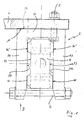
- In der Zeichnung ist die Erfindung anhand eines Ausführungsbeispieles weitergehend erläutert. Es zeigen:
- Fig. 1 eine Draufsicht auf die neue Verbindung,
- Fig. 2 die Verbindung in Fig. 1 in Frontansicht.
- Das abgebrochen dargestellte Anschlußschwert ist mit 1 bezeichnet. An dem Anschlußschwert 1 ist die sogenannte Kontakttasche 2 in Flächenkontakt (11/22) mit dem Anschlußschwert 1 angeschraubt (3). Die U-profilförmige, mit ihrem Steg 21 gegen das Anschlußschwert 1 anliegende Kontakttasche 2 ist von oben (Pfeil A in Fig. 2) und von vorn (Pfeil B in Fig. 1) zum Einhängen des Bestandteil des Kabelkopfes 4′ bildenden massiven Anschlußstücks 4 zugänglich, das über seine Breitseiten (41) und (42) Flächenkontakt mit den Schenkeln 23, 24 der Kontakttasche 2 eingeht, wobei aus den nach unten einfallenden AnlageFlächen 26, 27 der Kontakttasche 2 einerseits und den korrespondierenden keilförmig verlaufenden Flächen (41, 42) des Anschlußstückes 4 andererseits ein Klemmsitz des Anschlußstückes 4 in der Kontakttasche 2 resultiert. Eine zusätzliche Sicherung bilden in die Überstände der Kontakttaschenschenkel 23, 24 über das Anschlußstück 4 eingezogene Schrauben 6.
- Die mit den Anlageflächen 26, 27 der Kontakttasche 2 korrespondierenden Keilflächen des Anschlußstücks 4 sind zum einen durch einen sich in Längsrichtung des Anschlußstücks 4 erstreckenden Rücksprung 43 bzw. 44 in dessen Breitseiten in im Abstand voneinander nebeneinander verlaufende Teilflächen 41 und 41′ bzw. 42 und 42′ und zum anderen durch einen eine Stufe bildende, sich über die Breite des Anschlußstückes 4 erstreckenden Rücksprung 46 bzw. 47 in seinen Breitseiten in Verbindung mit entsprechenden Rücksprüngen 28, 29 in den Schenkeln 23, 24 der Kontakttasche 2 dann auch noch weitergehend unter Bildung von insgesamt vier Kontaktbereichen aufgeteilt, von denen in der Zeichnung nur die Kontaktbereiche 41, 41′ und 41˝ bzw. 42, 42′ und 42˝ erscheinen.
- Anstelle der beim dargestellten Ausführungsbeispiel gewählten Zuordnung der Kontakttasche 2 zum Anschlußschwert 1 kann die Kontakttasche naturlich auch mit einem ihrer Schenkel gegen das Anschlußschwert zur Anlage kommend dem Anschlußschwert zugeordnet werden.
Claims (4)
Priority Applications (1)
| Application Number | Priority Date | Filing Date | Title |
|---|---|---|---|
| AT89121201T ATE93658T1 (de) | 1988-11-24 | 1989-11-16 | Loesbare verbindung eines hochstromkabels mit einem sammelschieneartigen anschlussschwert ueber eine kontakttasche. |
Applications Claiming Priority (2)
| Application Number | Priority Date | Filing Date | Title |
|---|---|---|---|
| DE8814630U | 1988-11-24 | ||
| DE8814630U DE8814630U1 (de) | 1988-11-24 | 1988-11-24 | Lösbare Verbindung eines Hochstromkabels mit einem sammelschienenartigen Anschlußschwert |
Publications (3)
| Publication Number | Publication Date |
|---|---|
| EP0370384A2 true EP0370384A2 (de) | 1990-05-30 |
| EP0370384A3 EP0370384A3 (en) | 1990-12-12 |
| EP0370384B1 EP0370384B1 (de) | 1993-08-25 |
Family
ID=6830141
Family Applications (1)
| Application Number | Title | Priority Date | Filing Date |
|---|---|---|---|
| EP89121201A Expired - Lifetime EP0370384B1 (de) | 1988-11-24 | 1989-11-16 | Lösbare Verbindung eines Hochstromkabels mit einem sammelschieneartigen Anschlussschwert über eine Kontakttasche |
Country Status (4)
| Country | Link |
|---|---|
| EP (1) | EP0370384B1 (de) |
| AT (1) | ATE93658T1 (de) |
| DE (2) | DE8814630U1 (de) |
| ES (1) | ES2044026T3 (de) |
Cited By (1)
| Publication number | Priority date | Publication date | Assignee | Title |
|---|---|---|---|---|
| EP0907218A3 (de) * | 1997-10-04 | 2000-06-07 | Flohe GmbH & Co | Lösbare Verbindung eines Hochstromkabels mit einem sammelschienenartigen Anschlussschwert |
Family Cites Families (4)
| Publication number | Priority date | Publication date | Assignee | Title |
|---|---|---|---|---|
| FR883154A (fr) * | 1941-10-31 | 1943-06-25 | Manuf Generale De Munitions | Mode de raccordement sans soudure de deux fils conducteurs |
| DE1131294B (de) * | 1957-11-20 | 1962-06-14 | Hart Mfg Company | Flachleiter-Sammelschiene |
| PL242700A1 (en) * | 1983-06-24 | 1985-01-02 | Przedsieb Montazu Elektryczneg | Connecting contact of single conductor |
| DE3423175A1 (de) * | 1984-06-22 | 1986-01-02 | Hans Flohe GmbH & Co, 4620 Castrop-Rauxel | Loesbare verbindung eines hochstromkabels mit einem anschlussschwert |
-
1988
- 1988-11-24 DE DE8814630U patent/DE8814630U1/de not_active Expired
-
1989
- 1989-11-16 AT AT89121201T patent/ATE93658T1/de not_active IP Right Cessation
- 1989-11-16 ES ES89121201T patent/ES2044026T3/es not_active Expired - Lifetime
- 1989-11-16 DE DE89121201T patent/DE58905383D1/de not_active Expired - Fee Related
- 1989-11-16 EP EP89121201A patent/EP0370384B1/de not_active Expired - Lifetime
Cited By (1)
| Publication number | Priority date | Publication date | Assignee | Title |
|---|---|---|---|---|
| EP0907218A3 (de) * | 1997-10-04 | 2000-06-07 | Flohe GmbH & Co | Lösbare Verbindung eines Hochstromkabels mit einem sammelschienenartigen Anschlussschwert |
Also Published As
| Publication number | Publication date |
|---|---|
| DE58905383D1 (de) | 1993-09-30 |
| EP0370384A3 (en) | 1990-12-12 |
| DE8814630U1 (de) | 1989-07-20 |
| EP0370384B1 (de) | 1993-08-25 |
| ATE93658T1 (de) | 1993-09-15 |
| ES2044026T3 (es) | 1994-01-01 |
Similar Documents
| Publication | Publication Date | Title |
|---|---|---|
| DE3688398T2 (de) | Spanformendes, spanabhebendes bearbeitungsverfahren. | |
| DE2544991B1 (de) | Schneideinsatz fuer die spanabhebende Bearbeitung | |
| EP0196613A2 (de) | Stromschienenhalter aus Kunststoff | |
| DE2529525C2 (de) | Schneideinsatz | |
| DE2903585C2 (de) | ||
| DE69012453T2 (de) | Formungsverfahren eines Schneidkontaktelementes. | |
| DE19800632C2 (de) | Anschluss zur Ultraschallschweißung und Verfahren zum Anschließen eines Anschlusses zur Ultraschallschweißung | |
| EP0370384A2 (de) | Lösbare Verbindung eines Hochstromkabels mit einem sammelschieneartigen Anschlussschwert über eine Kontakttasche | |
| DE19703751C1 (de) | Bauteilgruppe | |
| DE2331155C3 (de) | Anwendung des Kaltpreßschweißverfahrens zum Verbinden zweier gegeneinander gepreßter Werkstückteile | |
| DE3115285C2 (de) | ||
| DE3801354C2 (de) | ||
| DE2714885C3 (de) | Verdrahtungskanal | |
| DE3235717C2 (de) | Anschlußelement für eine Schaltungsträgerplatte | |
| DE2920468A1 (de) | Klemmelement zum loesbaren befestigen von in nuten eines gehaeuses eingeschobenen leiterplatten | |
| DE29616837U1 (de) | Reihenklemme mit Stromschiene | |
| DE7709597U1 (de) | Kabelkanal | |
| DE19800635A1 (de) | Verbindungsaufbau zum Verbinden eines umhüllten Drahts und eines Anschlusses und ein Verbindungsverfahren dafür | |
| DE8112347U1 (de) | Niederhalter für Sammler mit Aufreihstiften | |
| DE3234355C1 (de) | Stützvorrichtung für ein Siebband | |
| DE2713656A1 (de) | Drahtfuehrungselement fuer verteilerleisten | |
| DE2416577C2 (de) | Bauteil für eine elektrische Klemmenleiste | |
| AT387253B (de) | Verbundtraeger, bestehend aus besaeumten rundhoelzern | |
| AT397852B (de) | Zündelektrode | |
| DE1954342A1 (de) | Steckverbindung fuer elektrische Leiter |
Legal Events
| Date | Code | Title | Description |
|---|---|---|---|
| PUAI | Public reference made under article 153(3) epc to a published international application that has entered the european phase |
Free format text: ORIGINAL CODE: 0009012 |
|
| AK | Designated contracting states |
Kind code of ref document: A2 Designated state(s): AT BE CH DE ES FR GB IT LI SE |
|
| PUAL | Search report despatched |
Free format text: ORIGINAL CODE: 0009013 |
|
| AK | Designated contracting states |
Kind code of ref document: A3 Designated state(s): AT BE CH DE ES FR GB IT LI SE |
|
| 17P | Request for examination filed |
Effective date: 19910219 |
|
| 17Q | First examination report despatched |
Effective date: 19921201 |
|
| GRAA | (expected) grant |
Free format text: ORIGINAL CODE: 0009210 |
|
| AK | Designated contracting states |
Kind code of ref document: B1 Designated state(s): AT BE CH DE ES FR GB IT LI SE |
|
| REF | Corresponds to: |
Ref document number: 93658 Country of ref document: AT Date of ref document: 19930915 Kind code of ref document: T |
|
| REF | Corresponds to: |
Ref document number: 58905383 Country of ref document: DE Date of ref document: 19930930 |
|
| ITF | It: translation for a ep patent filed | ||
| GBT | Gb: translation of ep patent filed (gb section 77(6)(a)/1977) |
Effective date: 19931029 |
|
| ET | Fr: translation filed | ||
| REG | Reference to a national code |
Ref country code: ES Ref legal event code: FG2A Ref document number: 2044026 Country of ref document: ES Kind code of ref document: T3 |
|
| PLBE | No opposition filed within time limit |
Free format text: ORIGINAL CODE: 0009261 |
|
| STAA | Information on the status of an ep patent application or granted ep patent |
Free format text: STATUS: NO OPPOSITION FILED WITHIN TIME LIMIT |
|
| 26N | No opposition filed | ||
| EAL | Se: european patent in force in sweden |
Ref document number: 89121201.1 |
|
| PGFP | Annual fee paid to national office [announced via postgrant information from national office to epo] |
Ref country code: AT Payment date: 20001128 Year of fee payment: 12 |
|
| REG | Reference to a national code |
Ref country code: GB Ref legal event code: IF02 |
|
| PGFP | Annual fee paid to national office [announced via postgrant information from national office to epo] |
Ref country code: GB Payment date: 20020214 Year of fee payment: 13 |
|
| PGFP | Annual fee paid to national office [announced via postgrant information from national office to epo] |
Ref country code: CH Payment date: 20020215 Year of fee payment: 13 |
|
| PGFP | Annual fee paid to national office [announced via postgrant information from national office to epo] |
Ref country code: BE Payment date: 20020220 Year of fee payment: 13 |
|
| PGFP | Annual fee paid to national office [announced via postgrant information from national office to epo] |
Ref country code: SE Payment date: 20020221 Year of fee payment: 13 |
|
| PGFP | Annual fee paid to national office [announced via postgrant information from national office to epo] |
Ref country code: ES Payment date: 20020225 Year of fee payment: 13 |
|
| PGFP | Annual fee paid to national office [announced via postgrant information from national office to epo] |
Ref country code: FR Payment date: 20020228 Year of fee payment: 13 |
|
| PGFP | Annual fee paid to national office [announced via postgrant information from national office to epo] |
Ref country code: DE Payment date: 20020326 Year of fee payment: 13 |
|
| PG25 | Lapsed in a contracting state [announced via postgrant information from national office to epo] |
Ref country code: GB Free format text: LAPSE BECAUSE OF NON-PAYMENT OF DUE FEES Effective date: 20021116 Ref country code: AT Free format text: LAPSE BECAUSE OF NON-PAYMENT OF DUE FEES Effective date: 20021116 |
|
| PG25 | Lapsed in a contracting state [announced via postgrant information from national office to epo] |
Ref country code: SE Free format text: LAPSE BECAUSE OF NON-PAYMENT OF DUE FEES Effective date: 20021117 Ref country code: ES Free format text: LAPSE BECAUSE OF NON-PAYMENT OF DUE FEES Effective date: 20021117 |
|
| PG25 | Lapsed in a contracting state [announced via postgrant information from national office to epo] |
Ref country code: LI Free format text: LAPSE BECAUSE OF NON-PAYMENT OF DUE FEES Effective date: 20021130 Ref country code: CH Free format text: LAPSE BECAUSE OF NON-PAYMENT OF DUE FEES Effective date: 20021130 Ref country code: BE Free format text: LAPSE BECAUSE OF NON-PAYMENT OF DUE FEES Effective date: 20021130 |
|
| BERE | Be: lapsed |
Owner name: HANS *FLOHE G.M.B.H. & CO. Effective date: 20021130 |
|
| PG25 | Lapsed in a contracting state [announced via postgrant information from national office to epo] |
Ref country code: DE Free format text: LAPSE BECAUSE OF NON-PAYMENT OF DUE FEES Effective date: 20030603 |
|
| EUG | Se: european patent has lapsed | ||
| GBPC | Gb: european patent ceased through non-payment of renewal fee | ||
| REG | Reference to a national code |
Ref country code: CH Ref legal event code: PL |
|
| PG25 | Lapsed in a contracting state [announced via postgrant information from national office to epo] |
Ref country code: FR Free format text: LAPSE BECAUSE OF NON-PAYMENT OF DUE FEES Effective date: 20030731 |
|
| REG | Reference to a national code |
Ref country code: FR Ref legal event code: ST |
|
| REG | Reference to a national code |
Ref country code: ES Ref legal event code: FD2A Effective date: 20031213 |
|
| PG25 | Lapsed in a contracting state [announced via postgrant information from national office to epo] |
Ref country code: IT Free format text: LAPSE BECAUSE OF NON-PAYMENT OF DUE FEES;WARNING: LAPSES OF ITALIAN PATENTS WITH EFFECTIVE DATE BEFORE 2007 MAY HAVE OCCURRED AT ANY TIME BEFORE 2007. THE CORRECT EFFECTIVE DATE MAY BE DIFFERENT FROM THE ONE RECORDED. Effective date: 20051116 |