EP0370496A2 - Kunststoffzuführvorrichtung für Zahnstützvorrichtung und damit versehener Formkosten - Google Patents
Kunststoffzuführvorrichtung für Zahnstützvorrichtung und damit versehener Formkosten Download PDFInfo
- Publication number
- EP0370496A2 EP0370496A2 EP89121585A EP89121585A EP0370496A2 EP 0370496 A2 EP0370496 A2 EP 0370496A2 EP 89121585 A EP89121585 A EP 89121585A EP 89121585 A EP89121585 A EP 89121585A EP 0370496 A2 EP0370496 A2 EP 0370496A2
- Authority
- EP
- European Patent Office
- Prior art keywords
- flask
- cylinder
- spring
- piston
- denture base
- Prior art date
- Legal status (The legal status is an assumption and is not a legal conclusion. Google has not performed a legal analysis and makes no representation as to the accuracy of the status listed.)
- Granted
Links
- 239000000463 material Substances 0.000 title claims abstract description 62
- 239000004033 plastic Substances 0.000 title claims abstract description 15
- 229920003023 plastic Polymers 0.000 title claims abstract description 15
- 229920002725 thermoplastic elastomer Polymers 0.000 claims description 8
- 239000011505 plaster Substances 0.000 description 22
- 238000006116 polymerization reaction Methods 0.000 description 14
- 229920001971 elastomer Polymers 0.000 description 11
- 238000003825 pressing Methods 0.000 description 10
- 230000002093 peripheral effect Effects 0.000 description 8
- XLYOFNOQVPJJNP-UHFFFAOYSA-N water Substances O XLYOFNOQVPJJNP-UHFFFAOYSA-N 0.000 description 8
- 208000015943 Coeliac disease Diseases 0.000 description 7
- 210000003254 palate Anatomy 0.000 description 6
- 239000011347 resin Substances 0.000 description 6
- 229920005989 resin Polymers 0.000 description 6
- 238000010438 heat treatment Methods 0.000 description 5
- 210000004400 mucous membrane Anatomy 0.000 description 5
- 238000001816 cooling Methods 0.000 description 4
- 238000000034 method Methods 0.000 description 4
- 238000000465 moulding Methods 0.000 description 4
- 239000007787 solid Substances 0.000 description 4
- VVQNEPGJFQJSBK-UHFFFAOYSA-N Methyl methacrylate Chemical compound COC(=O)C(C)=C VVQNEPGJFQJSBK-UHFFFAOYSA-N 0.000 description 3
- 210000001909 alveolar process Anatomy 0.000 description 3
- 230000000694 effects Effects 0.000 description 3
- 238000002347 injection Methods 0.000 description 3
- 239000007924 injection Substances 0.000 description 3
- 239000007788 liquid Substances 0.000 description 3
- 239000002184 metal Substances 0.000 description 3
- 229910052751 metal Inorganic materials 0.000 description 3
- 238000009413 insulation Methods 0.000 description 2
- 239000000178 monomer Substances 0.000 description 2
- 238000007789 sealing Methods 0.000 description 2
- 229920002379 silicone rubber Polymers 0.000 description 2
- 239000004945 silicone rubber Substances 0.000 description 2
- 229910001369 Brass Inorganic materials 0.000 description 1
- YCKRFDGAMUMZLT-UHFFFAOYSA-N Fluorine atom Chemical compound [F] YCKRFDGAMUMZLT-UHFFFAOYSA-N 0.000 description 1
- 239000000853 adhesive Substances 0.000 description 1
- 150000001336 alkenes Chemical class 0.000 description 1
- -1 alminum Substances 0.000 description 1
- 238000009835 boiling Methods 0.000 description 1
- 239000007767 bonding agent Substances 0.000 description 1
- 239000010951 brass Substances 0.000 description 1
- 230000006835 compression Effects 0.000 description 1
- 238000007906 compression Methods 0.000 description 1
- 239000004020 conductor Substances 0.000 description 1
- 238000010276 construction Methods 0.000 description 1
- 238000007796 conventional method Methods 0.000 description 1
- 238000007598 dipping method Methods 0.000 description 1
- 239000013536 elastomeric material Substances 0.000 description 1
- 238000002474 experimental method Methods 0.000 description 1
- 229910052731 fluorine Inorganic materials 0.000 description 1
- 239000011737 fluorine Substances 0.000 description 1
- 239000011796 hollow space material Substances 0.000 description 1
- 210000001847 jaw Anatomy 0.000 description 1
- 238000004898 kneading Methods 0.000 description 1
- 230000013011 mating Effects 0.000 description 1
- 150000002739 metals Chemical class 0.000 description 1
- 238000002156 mixing Methods 0.000 description 1
- 239000000203 mixture Substances 0.000 description 1
- 238000012986 modification Methods 0.000 description 1
- 230000004048 modification Effects 0.000 description 1
- JRZJOMJEPLMPRA-UHFFFAOYSA-N olefin Natural products CCCCCCCC=C JRZJOMJEPLMPRA-UHFFFAOYSA-N 0.000 description 1
- 229920003229 poly(methyl methacrylate) Polymers 0.000 description 1
- 239000004926 polymethyl methacrylate Substances 0.000 description 1
- 239000000843 powder Substances 0.000 description 1
- 229910001220 stainless steel Inorganic materials 0.000 description 1
- 239000010935 stainless steel Substances 0.000 description 1
- 239000012815 thermoplastic material Substances 0.000 description 1
Images




Classifications
-
- A—HUMAN NECESSITIES
- A61—MEDICAL OR VETERINARY SCIENCE; HYGIENE
- A61C—DENTISTRY; APPARATUS OR METHODS FOR ORAL OR DENTAL HYGIENE
- A61C13/00—Dental prostheses; Making same
- A61C13/12—Tools for fastening artificial teeth; Holders, clamps, or stands for artificial teeth
- A61C13/14—Vulcanising devices for artificial teeth
-
- A—HUMAN NECESSITIES
- A61—MEDICAL OR VETERINARY SCIENCE; HYGIENE
- A61C—DENTISTRY; APPARATUS OR METHODS FOR ORAL OR DENTAL HYGIENE
- A61C13/00—Dental prostheses; Making same
- A61C13/12—Tools for fastening artificial teeth; Holders, clamps, or stands for artificial teeth
- A61C13/16—Curing flasks; Holders therefor
-
- B—PERFORMING OPERATIONS; TRANSPORTING
- B29—WORKING OF PLASTICS; WORKING OF SUBSTANCES IN A PLASTIC STATE IN GENERAL
- B29C—SHAPING OR JOINING OF PLASTICS; SHAPING OF MATERIAL IN A PLASTIC STATE, NOT OTHERWISE PROVIDED FOR; AFTER-TREATMENT OF THE SHAPED PRODUCTS, e.g. REPAIRING
- B29C45/00—Injection moulding, i.e. forcing the required volume of moulding material through a nozzle into a closed mould; Apparatus therefor
- B29C45/17—Component parts, details or accessories; Auxiliary operations
- B29C45/46—Means for plasticising or homogenising the moulding material or forcing it into the mould
- B29C45/57—Exerting after-pressure on the moulding material
-
- B—PERFORMING OPERATIONS; TRANSPORTING
- B29—WORKING OF PLASTICS; WORKING OF SUBSTANCES IN A PLASTIC STATE IN GENERAL
- B29C—SHAPING OR JOINING OF PLASTICS; SHAPING OF MATERIAL IN A PLASTIC STATE, NOT OTHERWISE PROVIDED FOR; AFTER-TREATMENT OF THE SHAPED PRODUCTS, e.g. REPAIRING
- B29C45/00—Injection moulding, i.e. forcing the required volume of moulding material through a nozzle into a closed mould; Apparatus therefor
- B29C45/17—Component parts, details or accessories; Auxiliary operations
- B29C45/46—Means for plasticising or homogenising the moulding material or forcing it into the mould
- B29C45/57—Exerting after-pressure on the moulding material
- B29C45/572—Exerting after-pressure on the moulding material using movable mould wall or runner parts
-
- B—PERFORMING OPERATIONS; TRANSPORTING
- B29—WORKING OF PLASTICS; WORKING OF SUBSTANCES IN A PLASTIC STATE IN GENERAL
- B29C—SHAPING OR JOINING OF PLASTICS; SHAPING OF MATERIAL IN A PLASTIC STATE, NOT OTHERWISE PROVIDED FOR; AFTER-TREATMENT OF THE SHAPED PRODUCTS, e.g. REPAIRING
- B29C45/00—Injection moulding, i.e. forcing the required volume of moulding material through a nozzle into a closed mould; Apparatus therefor
- B29C45/17—Component parts, details or accessories; Auxiliary operations
- B29C45/72—Heating or cooling
- B29C45/73—Heating or cooling of the mould
Definitions
- the present invention relates to a device for supplying plastic material for denture base and a flask with the same.
- thermoplastic elastomer e.g. thermoplastic elastomer
- MMA liquified methyl methacrylate
- the material expands due to boiling of the liquid MMA monomer, heat-expansion of PMMA, and the like. As polimerization and cooling progress, the material shrinks, and heat-deformation results.
- Japanese Unexamined Utility model Publication No. 145519/1986 disclosed a device having a piston and cylinder for supplying the shortage of PMMA when the material shrinks.
- that device has a drawback in that bubbles and cavities tend to be produced in the denture bases, because the PMMA material expands initially, then shrinks.
- the above-mentioned Japanese Unexamined Patent Publication No. 342/1987 discloses a device for forming a liner made of thermoplastic elastomer and for fixing the liner on the backside of a denture base when PMMA material is polimerized and set under heating at the same time.
- the thermoplastic elastomer also expands under heating, and shrinks when cooled. Thus, bubbles and cavities are generated in the resulting liner also.
- the main object of the present invention is to provide a device for supplying plastic material for denture base or the like, which does not produce bubbles and cavities in the denture base or the like.
- a device for supplying plastic material into a flask comprising a cylinder having an inside end opening into the cavity of a flask, a piston slidably inserted in the cylinder, a spring urging the piston toward the inside of the flask, a stopper restricting the outside stroke end of the piston, and a means for adjusting the elastic force of the spring.
- the means for adjusting the elastic force of the spring preferably has a spring receiver for supporting one end of the spring, the other end of which is abutted against the outside of the piston, a screw rod having an inside end connected to the spring receiver and having an outer screw portion, a nut member having an inner screw mating with the outer screw of the screw rod and fixed at the outside end of the cylinder, and a handle for rotating the screw rod.
- a flask with the above-mentioned material supplying device comprising an upper half and a lower half, the plan view of each half having substantially rectangular shape, two material supplying devices of Claim 1 arranged at two corners adjacent to the same side of one of the halves, heat insulating members provided on a base surface and three side surfaces including the two corners of each of said halves.
- the means for adjusting the elastic force is adjusted to keep the force in its weakest state. Under that condition, the cavity of the flask is filled with plastic material for forming a denture base under pressure. At the same time, the cylinder is also filled with the same material under pressure. Therefore, the piston is moved outward and is stopped by the stopper.
- the adjusting means is operated to strengthen the force of the spring. In that condition, even if the plastic material (PMMA) shrinks due to progress of polymerization or cooling, the correct form is created because the same material is supplied from the cylinder.
- the bonding is strengthened because the inner space where the denture base is formed is kept under high pressure.
- the adjusting means is operated after the polymerization begins in the above case.
- the means can be operated after the piston is supported by the stopper since all openings of the space are shut before the polymerization.
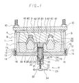
- the numeral 1 designates an upper flask or an upper half of a flask.
- the upper half 1 comprises an upper lid 2, a middle lid 3 and a frame 4 which are made of metal (for example, brass, alminum, stainless steel) and are formed to a substantially rectangular shape.
- the size of frame 4 is, for example, about 8 cm in width, about 10 cm in length and about 2.5 cm in height. As shown in the drawing, the inside surface of the frame slants so that the frame 4 can be easily removed from a plaster mold 37.
- Numeral 5 designates a lower flask or lower half of the flask.
- the lower half 5 comprises a lower lid 6 and a frame 7 being rectangular in shape. Further, the inside surface of the frame slants so that the free end side is enlarged.
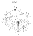
- Upper lid 2 and lower lid 6 are slightly larger than frames 4 and 7 and middle lid 2, and they have U-shaped cut portions 8 as shown in Fig. 2.
- Bolts 9 are inserted through the cut portions 8, and the bolts 9 and nuts 10 securely hold the upper lid 2 and the lower lid 6 and draw and fasten them together.
- Numeral 11 of Fig. 2 designates a hole formed near the center of the upper lid 2. This hole 11 exists in middle lid 3 as well. Hole 11 is utilized for fixing the plaster 37 and for injecting material for a denture base from the outside of the flask.
- Frame 7 is provided with fingers 12 projecting lateraly from lower end of the frame 7.
- Each finger 12 has a U-shaped cut portion 13.
- Lower lid 6 has the same U-shaped cut portions 14.
- Bolts or screws 15 are inserted in the cut portions 13 and 14, and are fastened by nuts 16 to fasten frame 7 and lower lid 6.
- Numeral 17 in Fig. 1 designates a material supplying device according to the present invention detachably mounted through the main side of the lower flask 5, i.e. the lower lid 6.
- the device 17 comprises a cylinder 19, a piston 20, a coil spring 21, a stopper 22 and a means for adjusting the elastic force of spring 21.
- the cylinder 19 is inserted through hole or opening 18 formed in lower lid 6 and is attached to the lower lid 6.
- the piston 20 is housed in the cylinder for reciprocal linear motion.
- the spring 21 is housed in the cylinder, and an upper (inside) end of the spring is abutted against the lower side of the piston 20 for elastically urging the piston 20 toward the inside of the flask.
- the spring has a coil shape, for example, with about 10 mm in diameter and about 3.0 cm in length.
- the stopper 22 is a step portion formed in the cylinder 19 for restricting the stroke-end of the piston at the most descended position, i.e. the most outside position.
- the inner end of cylinder 19 is open, and the outside end, situated outside of the lower flask 5, is closed. Further, the cylinder 19 is divided into a first cylinder 24 having an inside diameter of about 13 mm and a second cylinder 25 having an inside diameter of about 11 mm, such that the cylinder 19 is detachable from the flask.
- the second cylinder 25 is screwed onto the outer screw portion 26 of the first cylinder projecting from the outside surface of the lower lid 6.
- An O-ring 27 is provided between the second cylinder 25 and the lower lid 6.
- the first cylinder 24 has an upper portion 28 (about 13 mm in inside diameter) and a lower reduced portion 29 (about 11 mm in inside diameter).
- the opening 18 of the lower lid 6 has a diameter slightly larger than the outside diameter of the reduced portion 29 so that the reduced portion can be inserted, and the large diameter portion 28 engages with the edge surrounding the hole 18.
- the piston 20 has a cup-like shape and is provided with a seal member 30 made of rubber or the like which is fixed on the head of the cup-like member.
- the first cylinder 24 has a step 22 about 1 mm in width, for example, on the inside surface at the position where the outside diameter changes, i.e. between the large diameter portion 28 and the reduced portion 29. Further, the piston 20 is made so as to slide in the large diameter portion 28. Therefore, the piston 20 is stopped by abutting against the step 22, and is prevented from descending further.
- the step 22 functions as the above-mentioned stopper in the present invention.
- the above-mentioned spring force adjusting means 23 comprises a screw rod 32, a screw hole (nut member) 31 formed in the outside end, i.e. the closed end, of the second cylinder 25, a disc-like spring receiver 33 attached on the inside end of the screw rod 32 so as to receive the outside end of the spring 21, and a handle member 34 provided on the outside end of the screw rod 32.
- the spring receiver 33 is attached on the screw rod 32 by means of a bolt 35 so that rotation of the screw rod 32 is not transmitted to the spring receiver 33.
- the numeral 36 designates a hollow space for forming a denture base, and the space 36 is constructed by surrounding with solid plaster 37 and 38, and a plaster model 39 of the alveolar ridge of a patient.
- the space 36 can be formed by known methods using wax or the like.
- the numeral 40 designates artificial teeth enbedded in the solid plaster 37.
- the space 36 and the inner space of the first cylinder 24 are filled with plastic material for denture base, for example, PMMA dough 41.
- the PMMA in the space 36 and the PMMA in the cylinder 24 are connected to each other by a sprue 42 (grooves communicating from space 36 to the inner space of the first cylinder 24).
- the spring receiver 33 of the second cylinder 25 is lowered to the outside stroke end. Then, the force of spring 21 is in its weakest state, and the piston 20 comes to rest against the step 22 of the large diameter portion 28. Therefore, the maximum volume of PMMA in the cylinder 19 is restricted.
- the upper lid 2 and the lower lid 6 are tightly bounded by the bolts 9 and the nuts 10. Then, the handle 34 is rotated to push the spring receiver 33 up. The spring 21 is thus compressed, and the piston is pressed forcefully against the paste-like PMMA dough 41.
- the force of the spring can be adjusted by operating the handle 34.
- the pressing force is about 10 kg in this embodiment.
- the flask is placed in a pressure cooker or the like, and is heated to about 100 to 120°C to be polymerized.
- the piston 20 of the material supplying device 17 cannot descend any further. Therefore, the interior pressure of the space 36 for forming the denture base is kept in high, and neither bubbles nor molding cavities are produced as the PMMA is polymerized, then shrinks.
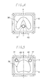
- Fig. 4 shows an example arrangement for the supplying device 17 when a lower denture is produced.
- the device 17 is positioned on a center line a and at a position shifted slightly down (to the rear).
- the device 17 communicats to the space 36 for forming the denture through sprue 43.
- Fig. 5 shows an arrangement of the material supplying device 17 when an upper denture is produced.
- Two devices 17 are positioned at the upper (in the drawing) corners and communicates to the space 36 through sprues 43.
- the reason why the frame 7 of the flask has a rectangular shape is to obtain spaces for positioning the supplying devices 17.
- the numeral 44 designates small openings formed in the frame 7 for positioning the frames 1 and 7. Pins (not shown) or the like provided on the upper frame 1 at the corresponding positions are inserted through the opening 44 of the frame 7 in order to correctly put the upper frame 1 on the lower frame 7.
- Figs. 6 through 10 there are shown the second embodiment of the flask of the present invention where a liner made of thermoplastic elastomer to be formed and bonded on the back surface (mucous membrain surface) of a denture base is used.
- the numeral 5 designates a flask
- the numerals 6 and 7 designate a lower lid and a lower frame, respectively.
- the lower lid 6 and the lower frame 7 are fixed to each other by bolts 17 and nuts 16 as described above with reference to Fig. 1.
- the numeral 39 designates a plaster model embedded in solid plaster 38
- the numeral 24 designates the first cylinder of a material supplying device 17.
- the cylinder 24 is inserted into a hole 18 and temporarily fixed to the lower lid 6 before the plaster 38 is poured in the flask 5.
- a piston 20 is slidably inserted the first cylinder 24.
- the open inside end of the first cylinder is plugged with a rubber plug 45 in order to prevent the plaster 38 from entering the first cylinder 24.
- the rubber plug 45 has two lateral projections 46 for forming sprue grooves.
- a wax layer 47 is placed on the plaster model 39 and is formed to a shape corresponding to the liner to be formed.
- the frame 4 of the upper flask 1 is put on the lower flask 5, liquid plaster 52 (see Fig. 8) is poured into the frame 4, and a middle lid 3 is put thereon.
- the flask is dipped in hot water of 100°C. Then, the wax layer 47 is softened. After the upper and lower halves of the flask are separated, the lower half is further heated by dipping in hot water to completely remove the wax.
- the above-mentioned middle lid 3 and the frame 4 are utilized as a pressing die for forming the liner.
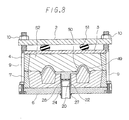
- the rubber plug 45 is removed as shown in Fig. 8, and a previously heated and softened material 49 made of thermoplastic elastomer for the liner is inserted between the pressing die and the lower flask 5. Therefore, the space for forming the denture base, i.e. a space 50 for forming a liner in the present case, and the space in the large diameter portion 28 of the first cylinder 24 are filled with the material of liner 49. With the present construction, the piston 20 is stopped by abutting against the step 22. Olefin thermoplastic elastomer is the preferred, but not necessarily only, lining material.
- a rubber ring 51 is sandwiched between the middle lid 3 and the upper lid 2, and the upper lid 2 and the lower lid 6 are fastened to each other by bolts 9 and nuts 10. At this point, the rubber ring 51 is compressed due to the clamping of the bolts 9 and nuts 10, and it applies constant and regular elastic pressure between the pressing die and the lower flask 5.
- the flask 5 is dipped in hot water (about 100°C).
- hot water about 100°C.
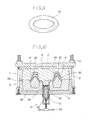
- Fig. 9 shows an embodiment of shape of the rubber ring 51.
- the rubber ring 51 can be formed of silicone rubber, or the like.
- the pressing die is removed. Then, the outside surface of the liner 49 is coated with a bonding or adhesive agent. Then, as shown in Fig. 10, instead of the pressing die, the upper flask 1 having a space 36 for forming the denture base including a space for forming the lining is put on the lower flask 5 so as to clamp the PMMA dough 41 therebetween.
- the upper flask 1 is trial-pressed against the lower flask 5 several times, and the PMMA flashing is cut and removed.
- the plaster 37 in the upper flask 1 is previously prepared by building wax onto the plaster model 39, forming the wax to the shape of the denture base to be formed, arranging artificial teeth 40 to make a denture model, and then removing the wax.
- Known methods can be used to embed and fix the artificial teeth in the plaster 37.
- the handle 34 is operated to compress the spring by about one half to one third of full compression. This step is performed to prevent bubbles, mold cavities, and the like from forming in the PMMA when the PMMA 41 is polymerized and set as in the above mentioned first embodiment.
- the flasks 1 and 5 are dipped in a pressure cooker, and are heated to about 100 to 120°C. Then, the PMMA 41 is polymerized and set, and the liner 49 is bonded to the PMMA at the same time.
- the flasks 1 and 5 are taken out of the pressure cooker.
- the handle 34 is operated then immediately to compress the spring to the maximum compressed state, and pressure is thereby applied to the lining material 49 in the first cylinder 24 through the piston 20. Thereafter, the flasks 1 and 5 are naturally cooled.
- the handle 34 can be operated (i.e. the spring can be compressed) before the flasks 1 and 5 are heated.
- Such method may be easy to perform.
- the liner 49 shrinks. However, since additional lining material is supplied from the first cylinder 24, the liner remains free of bubbles, mold cavities and deformation.
- a coil spring of 0.7 kg/mm in spring constant and 30 mm in normal length is used.
- the coil spring can effect 10 kg pressing force when compressed by 15 mm.
- the amount of lining material on the back surface of the denture base is about 6 grams, and the amount of material additionally supplied from the supplying device 17 is about 1 gram.
- the device and flask of the present invention is not limited to them. It can be utilized for forming orthodontic tools, mouthpieces, attachments, jaw restoration material, or the like.
- the work "denture base” includes the above-mentioned tools.
- the conventional flask is generally formed in a shape corresponding to the shape of a denture, i.e. in a semicircle shape.
- heat is conducted from the peripheral surfaces to the center and the denture is gradually set from the peripheral portions thereof.
- the peripheral portions i.e. alveolar portion, cheek side portions and lip side portions are thick, and the center semicircular portion, i.e. palate portion is thin. Therefore, the palate portion which is heated later is strongly influenced by shrinkage due to the polymerization.
- the material of the palate portion which set firstly, is pulled in the direction of shrinkage during the polymerization of the peripheral thick portions, and is noticeably deformed.
- the denture prepared by conventional methods there is usually a gap between the palate portion of an upper denture and mucous membrane of the patient's palate. Therefore, the denture cannot be in close contact the mucous membrane.
- the third embodiment of the present invention has been improved in order to keep the deformation to a minimum.
- the third embodiment is described hereinafter in detail with reference to Figs. 11 to 17.
- the numeral 5 designates a lower flask as in the above-mentioned embodiments.
- Numeral 60 designates a heat-insulating member made of a material having good heat-insulation, such as silicone rubber, which is contained in the flask 5.
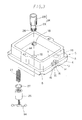
- the heat-insulating member 60 is formed to cover three inside walls 61, 62, 63 including the corners where holes 18 are formed, and a bottom surface 64 which is a main inside surface.
- the remaining side surface 65 of the flask 5 is free from heat insulation.
- heat is applied through the insulation-free side, and is gradually conducted toward the corners surrounding the holes 18 as shown in Fig. 14 by lines b and arrow X.
- the heat-insulating member 60 comprises laminer portions 66 of about 3 to 6 mm in thickness covering the above-mentioned three side surfaces and the bottom surface, and plural fins projecting from the laminer portions 66 toward the interior of the flask 5.
- the length of the fins 67 should be such that the free end of each fin reaches the denture model leaving only a slight gap or is actually in contact with the denture model. Even if the fin is in contact with the denture model, there is no problem since the fin is flexible.
- Fins 57 near the insulation-free side i.e. fins situated at mesial are larger than the other fins.
- the fins are provided to ensure that heat is conducted from only the insulation-free side. That is to say, the temperature will be lowest at the holes 18 due to the placement of the fins. Further, since the fins separate plaster, the solid plaster can be easily broken when the denture is taken out of the plaster.
- Numeral 68 designates a hole of the same size as the holes 18 of the flask 5. They are positioned to align with those holes 18.
- the same heat-insulating member 69 is also provided in the upper flask 1 (see Fig. 12).
- the heat-insulating member 69 has a lid member 71 made of the same material at the upper side 70, and liquid plaster can be poured into the flask 1 through the opening after the lid member 71 is removed.
- the under surface of the lid member 71 is also provided with heat-insulating fins 73.
- the center of the lid member 71 is thick, and the fins 73 are provided on the under surface of the thick portion.
- the thick portion corresponds to the palate portion of the denture, and a large heat insulating effect is obtained there.
- Fig. 14 shows the arrangement of a space 36 for forming a denture base and the first and second supplying devices 74,75 in the lower flask 5.
- the first and the second supplying devices 74,75 are positioned near the peripheral portions.
- the numeral 76 designates sprues communicating to the peripheral portion of the space 36 for forming denture base from the supplying devices 74 and 75.
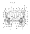
- Fig. 16 is a sectional view showing the lower flask 5 shown in Fig. 14, on which an upper flask 1 with embedded artificial teeth 40 has been placed.
- the first supplying device 74 is attached to one of the holes 18 (to left of drawing), and the second supplying device 75 is attached to the other hole 18 (to right of drawing).
- Each of first and second supplying devices 74 and 75 has an inside cylinder 78 and a cylinder pipe 79.
- the cylinder pipe 79 is made of low-heat-conductive material, such as fluorine-containing resin, and the inside cylinder is made of metal.
- the structure of the first supplying device is such that the cylinder pipe 79 fits on the outside of the inside cylinder 78, and a piston 81 is stopped by abutting against an end 90 of the inside cylinder 78. That is to say, the end 90 functions as a stopper.
- the numeral 77 designates the second cylinder situated outside the flask.
- the second supplying device 75 is constructed such that the cylinder pipe 79 is inserted inside the inside cylinder 91.
- the cylinder pipe 79 and the inside cylinder have the same inside diameter in order to allow the seal member and the piston to slide through the cylinder pipe 79 and the inside cylinder 91.
- a pin 81 is fixed to an upper portion as a stopper for restricting the descent of the piston 81.
- the numeral 92 designates a spring receiver, and the numeral 93 designates a second cylinder. The remaining parts are the same as the first supplying device 71.
- the springs 21 of the devices having the same spring force are used.
- the unformity in the designs of the devices is to provide the same material-supplying capacity to each device.
- the spring force of the spring 21 is preferably about 2 to 5 kg/cm2.
- the above-mentioned devices can be operated as same as the first embodiment.
- the handle 34 is rotated with fingers to press up the spring receivers 32 and 92.
- the springs 21 are compressed, the combined flasks are dipped in hot water to polymerize the material.
- the flasks are put in a pressure cooker (not shown) such that the insulation-free side is directed to the lower side, and level of hot water is adjusted to reach the center of the denture. In this situation, heat is conducted from the center portion to the peripheral portion of the denture, and the peripheral portion is polymerized and set last.
- Fig. 17 shows a material charging device 84 to be used at the step before the step shown in Fig. 16. That is, the device is used when a space 36 for forming a denture base is charged with denture material.
- the charging device 84 is attached in place of the second cylinder 93 of the second supplying device.
- the charging device comprises a cylinder 85, a charging tube 86 and a piston 87, which are made of metals or plastics.
- the numeral 88 denotes an elastic tube made of elastomeric material such as rubber. The elastic tube 88 is expanded in diameter due to injection pressure when material is charged, and because the tube fits against the cylinder pipe, it provides a sealing effect.
- the cylinder 85 is made with a volume capable of containing material for forming a denture two or three times.
- Numeral 89 designates the piston of a hydraulic pressing machine.
- the cylinder 85 is filled with PMMA dough with an amount sufficient for at least one denture, and the injection tube 86 is inserted into the opening 18.
- the device is put on a hydraulic pressing machine together with the flask.
- the piston member 87 is pressed with the piston 89 to inject the PMMA 41 to the space 36 for forming the denture base through the cylinder pipe 79 and the sprues 76.
- the second cylinder 77 of the first supplying device 74 (see Fig. 16) is removed.
- the resin 41 flows into the cylinder pipe 79 of the first supplying device 74 through the sprue 76, and the cylinder pipe 79 is filled.
- the operator can know whether the pipe 79 is completely filled with resin or not.
- the injecting device 84 is removed from the flask, the sealing member 80 and the piston 81 are inserted into the inner cylinder 91, the spring 21 is housed, and the second cylinder 93 is set in place.
- the first and second supplying devices 74 and 75 are attached to the flask, and by rotating the handles 34 to compress the springs 21, the resin 41 can be automatically supplied into the space 36 for forming a denture base.
- a hydraulic stamping machine is used as the driving force for pressing the piston of the charging device 84, compressed air can also be utilized for that purpose.
- the material for a denture base is supplied from a supplying device, as the denture base is polymerized or the liner included in the denture base is heated. Therefore, even if the denture base shrinks when the denture base is heated for polimerization or cooled after the polymerization, the interior pressure of the flask is kept high, and bubbles and mold cavities are prevented.
- the material of the denture base is PMMA
- conventional devices present the problem of polymerization shrinkage.
- a denture base having a back mucous membrane surface precisely corresponding to the alveolar ridge of patient can be obtained, and the setting will feel good.
- the denture base material is for a liner
- the liner tends to shrink and the interior pressure of the flask is reduced when the liner is cooled after heating.
- a shortage of material results along with bubbles and molding cavities.
- the suppling device of the present invention the bubbles and molding cavities can be prevented since the material of the liner is charged with pressure by the supplying device. Further, a liner with the outer surface precisely corresponding to the mucous membrane surface can be obtained.
- material for a denture base or a liner can be charged after the spring is loosened (or at apropriate time) since the device has a spring force adjusting means. Therefore, the material can be easily charged, and the device can be easily operated.
- the interior pressure can be controlled for medium or maximum pressure by operating the handle. Therefore, when the denture base is polymerized or when the liner is cooled, the most suitable pressure can be applied in accordance with the situation.
- the size of spring contained therein is not limited since the device is installed on the main side of the flask such that it projects outside of the flask. Therefore, a very strong spring can be employed and sufficient pressure can be applied for any denture base to be formed.
- the flask of the present invention by providing heat-insulating members on the inside surfaces of the flask excepting one side surface and by providing the supplying device at the first position to which the heat is conducted, strain and deformation during polymerization of the denture base material can be effectively prevented, and a denture precisely corresonding to the alveolar ridge can be obtained.
Landscapes
- Health & Medical Sciences (AREA)
- Engineering & Computer Science (AREA)
- Mechanical Engineering (AREA)
- Manufacturing & Machinery (AREA)
- Epidemiology (AREA)
- Animal Behavior & Ethology (AREA)
- General Health & Medical Sciences (AREA)
- Public Health (AREA)
- Veterinary Medicine (AREA)
- Life Sciences & Earth Sciences (AREA)
- Dentistry (AREA)
- Oral & Maxillofacial Surgery (AREA)
- Dental Prosthetics (AREA)
- Dental Tools And Instruments Or Auxiliary Dental Instruments (AREA)
Applications Claiming Priority (2)
| Application Number | Priority Date | Filing Date | Title |
|---|---|---|---|
| JP296798/88 | 1988-11-24 | ||
| JP29679888 | 1988-11-24 |
Publications (3)
| Publication Number | Publication Date |
|---|---|
| EP0370496A2 true EP0370496A2 (de) | 1990-05-30 |
| EP0370496A3 EP0370496A3 (de) | 1991-10-09 |
| EP0370496B1 EP0370496B1 (de) | 1994-04-20 |
Family
ID=17838275
Family Applications (1)
| Application Number | Title | Priority Date | Filing Date |
|---|---|---|---|
| EP89121585A Expired - Lifetime EP0370496B1 (de) | 1988-11-24 | 1989-11-22 | Kunststoffzuführvorrichtung für Zahnstützvorrichtung und damit versehener Formkosten |
Country Status (3)
| Country | Link |
|---|---|
| EP (1) | EP0370496B1 (de) |
| KR (1) | KR0135520B1 (de) |
| DE (1) | DE68914789T2 (de) |
Cited By (3)
| Publication number | Priority date | Publication date | Assignee | Title |
|---|---|---|---|---|
| EP0806188A3 (de) * | 1996-05-10 | 1998-04-15 | Max Bosshart | Harzinjektor mit Muffel |
| KR102094640B1 (ko) * | 2019-06-05 | 2020-05-04 | (주) 디케이 문교 | 이종재질의 의치 성형용 플라스크 |
| CN112140396A (zh) * | 2020-09-05 | 2020-12-29 | 杭州海科杭环科技有限公司 | 一种环保的塑料颗粒处理装置 |
Families Citing this family (1)
| Publication number | Priority date | Publication date | Assignee | Title |
|---|---|---|---|---|
| CN105500569B (zh) * | 2015-12-30 | 2017-12-22 | 宁波市海创电器科技有限公司 | 自负重塑胶模具 |
Family Cites Families (4)
| Publication number | Priority date | Publication date | Assignee | Title |
|---|---|---|---|---|
| US1875660A (en) * | 1929-12-17 | 1932-09-06 | William F Rodin | Dental flask |
| DE824676C (de) * | 1949-02-16 | 1951-12-13 | Franz Strattner | Kuevette zur Herstellung von Zahnersatz |
| DE3322343A1 (de) * | 1983-06-22 | 1985-01-10 | Axel 3360 Osterode Nolden | Vorrichtung zum nachpressen von in eine hohlform eingepresste aushaertende kunststoffmasse bei der herstellung von prothesen |
| DE3610316A1 (de) * | 1985-03-29 | 1986-10-30 | Four Brain K.K., Hiroshima | Gebissbasis mit einer gummiartigen elastischen unterfutter- bzw. einlageschicht und verfahren zu seiner herstellung |
-
1989
- 1989-11-22 EP EP89121585A patent/EP0370496B1/de not_active Expired - Lifetime
- 1989-11-22 DE DE68914789T patent/DE68914789T2/de not_active Expired - Fee Related
- 1989-11-24 KR KR1019890017262A patent/KR0135520B1/ko not_active Expired - Fee Related
Cited By (5)
| Publication number | Priority date | Publication date | Assignee | Title |
|---|---|---|---|---|
| EP0806188A3 (de) * | 1996-05-10 | 1998-04-15 | Max Bosshart | Harzinjektor mit Muffel |
| US5858417A (en) * | 1996-05-10 | 1999-01-12 | Bosshart; Max | Resin injector with muffle |
| ES2132007A1 (es) * | 1996-05-10 | 1999-08-01 | Garzon Melero Yolanda | Inyector de resina con mufla |
| KR102094640B1 (ko) * | 2019-06-05 | 2020-05-04 | (주) 디케이 문교 | 이종재질의 의치 성형용 플라스크 |
| CN112140396A (zh) * | 2020-09-05 | 2020-12-29 | 杭州海科杭环科技有限公司 | 一种环保的塑料颗粒处理装置 |
Also Published As
| Publication number | Publication date |
|---|---|
| DE68914789D1 (de) | 1994-05-26 |
| EP0370496B1 (de) | 1994-04-20 |
| KR900007386A (ko) | 1990-06-01 |
| KR0135520B1 (ko) | 1998-04-22 |
| EP0370496A3 (de) | 1991-10-09 |
| DE68914789T2 (de) | 1994-08-18 |
Similar Documents
| Publication | Publication Date | Title |
|---|---|---|
| US5175008A (en) | Device for supplying plastic material for denture base and flask with the same | |
| US11660174B2 (en) | Dental devices and systems and methods for making the same | |
| US5324186A (en) | Apparatus for molding a dental prosthesis | |
| US4494934A (en) | Dental model base | |
| US20140234802A1 (en) | Molding artificial teeth in denture base disc | |
| US6730246B2 (en) | Duplication of lost dentures | |
| US4097992A (en) | Method for producing artificial dentures | |
| US9662189B2 (en) | Stress-reduced denture base disc | |
| US4094067A (en) | Method for producing artificial denture | |
| JPH0771564B2 (ja) | レジン義歯床の製造方法 | |
| EP0370496B1 (de) | Kunststoffzuführvorrichtung für Zahnstützvorrichtung und damit versehener Formkosten | |
| US4012838A (en) | Method for producing artificial dentures | |
| WO1995027447A1 (en) | Injection molding method and apparatus for preparing dental prosthesis and medical devices | |
| US5368481A (en) | Dental mold apparatus | |
| US20040197736A1 (en) | Manufacture of moulded dentures | |
| US7040885B2 (en) | Duplication of lost dentures | |
| JP3293250B2 (ja) | 歯科用フラスコ | |
| JPH11253463A (ja) | レジン義歯床の製造方法及び製造用具セット | |
| JPH0236858A (ja) | 義歯床用可塑材料の補充装置 | |
| JPH02224656A (ja) | 義歯床用可塑材料の補充装置及び該補充装置を備えたフラスコ | |
| JPH0221054Y2 (de) | ||
| JPH0221055Y2 (de) | ||
| JPH09206316A (ja) | 義歯床用レジン重合用フラスコ | |
| JPH0240963Y2 (de) | ||
| JPH0240962Y2 (de) |
Legal Events
| Date | Code | Title | Description |
|---|---|---|---|
| PUAI | Public reference made under article 153(3) epc to a published international application that has entered the european phase |
Free format text: ORIGINAL CODE: 0009012 |
|
| AK | Designated contracting states |
Kind code of ref document: A2 Designated state(s): CH DE FR GB LI |
|
| PUAL | Search report despatched |
Free format text: ORIGINAL CODE: 0009013 |
|
| AK | Designated contracting states |
Kind code of ref document: A3 Designated state(s): CH DE FR GB LI |
|
| 17P | Request for examination filed |
Effective date: 19910903 |
|
| 17Q | First examination report despatched |
Effective date: 19930310 |
|
| GRAA | (expected) grant |
Free format text: ORIGINAL CODE: 0009210 |
|
| AK | Designated contracting states |
Kind code of ref document: B1 Designated state(s): CH DE FR GB LI |
|
| REF | Corresponds to: |
Ref document number: 68914789 Country of ref document: DE Date of ref document: 19940526 |
|
| ET | Fr: translation filed | ||
| PLBE | No opposition filed within time limit |
Free format text: ORIGINAL CODE: 0009261 |
|
| STAA | Information on the status of an ep patent application or granted ep patent |
Free format text: STATUS: NO OPPOSITION FILED WITHIN TIME LIMIT |
|
| 26N | No opposition filed | ||
| PGFP | Annual fee paid to national office [announced via postgrant information from national office to epo] |
Ref country code: GB Payment date: 19951117 Year of fee payment: 7 |
|
| PGFP | Annual fee paid to national office [announced via postgrant information from national office to epo] |
Ref country code: FR Payment date: 19951120 Year of fee payment: 7 |
|
| PGFP | Annual fee paid to national office [announced via postgrant information from national office to epo] |
Ref country code: CH Payment date: 19951124 Year of fee payment: 7 |
|
| PGFP | Annual fee paid to national office [announced via postgrant information from national office to epo] |
Ref country code: DE Payment date: 19960105 Year of fee payment: 7 |
|
| PG25 | Lapsed in a contracting state [announced via postgrant information from national office to epo] |
Ref country code: GB Effective date: 19961122 |
|
| PG25 | Lapsed in a contracting state [announced via postgrant information from national office to epo] |
Ref country code: LI Effective date: 19961130 Ref country code: CH Effective date: 19961130 |
|
| GBPC | Gb: european patent ceased through non-payment of renewal fee |
Effective date: 19961122 |
|
| REG | Reference to a national code |
Ref country code: CH Ref legal event code: PL |
|
| PG25 | Lapsed in a contracting state [announced via postgrant information from national office to epo] |
Ref country code: FR Effective date: 19970731 |
|
| PG25 | Lapsed in a contracting state [announced via postgrant information from national office to epo] |
Ref country code: DE Effective date: 19970801 |
|
| REG | Reference to a national code |
Ref country code: FR Ref legal event code: ST |