EP0370621B1 - Rauchmessgerät - Google Patents
Rauchmessgerät Download PDFInfo
- Publication number
- EP0370621B1 EP0370621B1 EP89310798A EP89310798A EP0370621B1 EP 0370621 B1 EP0370621 B1 EP 0370621B1 EP 89310798 A EP89310798 A EP 89310798A EP 89310798 A EP89310798 A EP 89310798A EP 0370621 B1 EP0370621 B1 EP 0370621B1
- Authority
- EP
- European Patent Office
- Prior art keywords
- engine
- combustion
- fuel
- smoke
- level
- Prior art date
- Legal status (The legal status is an assumption and is not a legal conclusion. Google has not performed a legal analysis and makes no representation as to the accuracy of the status listed.)
- Expired
Links
- 239000000779 smoke Substances 0.000 title claims description 38
- 239000000446 fuel Substances 0.000 claims description 54
- 238000002485 combustion reaction Methods 0.000 claims description 51
- 230000005855 radiation Effects 0.000 claims description 16
- 238000000034 method Methods 0.000 claims description 15
- 230000006835 compression Effects 0.000 claims description 6
- 238000007906 compression Methods 0.000 claims description 6
- 238000012545 processing Methods 0.000 claims description 5
- 238000012360 testing method Methods 0.000 description 13
- 238000010586 diagram Methods 0.000 description 6
- 238000002347 injection Methods 0.000 description 6
- 239000007924 injection Substances 0.000 description 6
- 238000004519 manufacturing process Methods 0.000 description 3
- 238000009434 installation Methods 0.000 description 2
- 238000005259 measurement Methods 0.000 description 2
- 230000001133 acceleration Effects 0.000 description 1
- 238000004458 analytical method Methods 0.000 description 1
- 238000004364 calculation method Methods 0.000 description 1
- 230000007423 decrease Effects 0.000 description 1
- 230000000694 effects Effects 0.000 description 1
- 238000002474 experimental method Methods 0.000 description 1
- 238000007726 management method Methods 0.000 description 1
- 238000005070 sampling Methods 0.000 description 1
- 239000004071 soot Substances 0.000 description 1
Images

Classifications
-
- F—MECHANICAL ENGINEERING; LIGHTING; HEATING; WEAPONS; BLASTING
- F02—COMBUSTION ENGINES; HOT-GAS OR COMBUSTION-PRODUCT ENGINE PLANTS
- F02D—CONTROLLING COMBUSTION ENGINES
- F02D35/00—Controlling engines, dependent on conditions exterior or interior to engines, not otherwise provided for
- F02D35/02—Controlling engines, dependent on conditions exterior or interior to engines, not otherwise provided for on interior conditions
- F02D35/022—Controlling engines, dependent on conditions exterior or interior to engines, not otherwise provided for on interior conditions using an optical sensor, e.g. in-cylinder light probe
-
- F—MECHANICAL ENGINEERING; LIGHTING; HEATING; WEAPONS; BLASTING
- F02—COMBUSTION ENGINES; HOT-GAS OR COMBUSTION-PRODUCT ENGINE PLANTS
- F02D—CONTROLLING COMBUSTION ENGINES
- F02D41/00—Electrical control of supply of combustible mixture or its constituents
- F02D41/02—Circuit arrangements for generating control signals
- F02D41/14—Introducing closed-loop corrections
- F02D41/1438—Introducing closed-loop corrections using means for determining characteristics of the combustion gases; Sensors therefor
- F02D41/1444—Introducing closed-loop corrections using means for determining characteristics of the combustion gases; Sensors therefor characterised by the characteristics of the combustion gases
- F02D41/1466—Introducing closed-loop corrections using means for determining characteristics of the combustion gases; Sensors therefor characterised by the characteristics of the combustion gases the characteristics being a soot concentration or content
- F02D41/1467—Introducing closed-loop corrections using means for determining characteristics of the combustion gases; Sensors therefor characterised by the characteristics of the combustion gases the characteristics being a soot concentration or content with determination means using an estimation
Definitions
- This invention relates to a method and apparatus for providing an indication of the level of smoke in the exhaust of a compression ignition engine.
- a known method and apparatus for the above purpose comprises drawing a predetermined volume of exhaust gas through a filter paper of a given area and then assessing the discolouration of the filter paper. Such a test even with semi-automatic equipment requires time to complete so that the results of a particular test may not be available for several seconds.
- An alternative method involves the measurement of the opacity of the smoke either by sampling or looking at the entire exhaust gas flow. This is adequate for steady speed and load conditions where the time taken for the smoke to travel from the combustion chamber to the measurement zone does not matter but it is not suitable for use under conditions where the speed and load are varying particularly where the signal is intended to be used in an engine management system. Moreover, care has to be taken to ensure that the radiation responsive surfaces do not become coated with soot.
- JP-A-63021348 describes (in an Otto-engine) the use of a radiation detector, detecting the end of combustion. From the thus detected end, the injection amount and timing is controlled to coincide with a prerecorded value.
- the object of the present invention is to provide a method and apparatus for the purpose specified in a simple and convenient form.
- a method of providing an indication of the level of smoke in the exhaust of a compression ignition engine comprises observing using a radiation responsive sensor, the radiation produced by the combustion of fuel in a combustion space of the engine, processing the signal produced by the sensor to provide a further signal representing the period of combustion of fuel in the combustion chamber and feeding said signal into a combustion period/smoke map for the engine to provide an indication of the level of smoke in the engine exhaust.
- an apparatus for providing an indication of the level of smoke in the exhaust of a compression ignition engine comprises a radiation responsive sensor adapted to be mounted on the engine so that it can observe the radiation produced by the combustion of fuel in a combustion chamber of the engine, means for processing the signal produced by the sensor to provide a second signal representing the period of combustion of fuel in the combustion chamber, a data map containing pre-recorded data showing the relationship between the level of smoke in the engine exhaust and the period of combustion of fuel and means for extracting from said data map the level of smoke which corresponds to said second signal.
- the curves illustrate the variations in the duration of the logarithm of the signal produced by a sensor or sensors mounted in the cylinder head of an engine, with time considered in terms of engine degrees of rotation and as the fuel quantity is varied for a given engine speed.
- the sensor is of the kind described in GB 2193804A. If the time is measured from the instant of fuel delivery to the combustion chamber it will be seen that after the ignition delay period the radiation signal rises rapidly to a peak valve from a residual level and then decays back to the residual level as the combustion of fuel is completed.
- the decaying portion of the envelope exhibits a characteristic double slope and the initial slope of the decaying portion of the envelope decreases as the amount of fuel supplied to the engine is increased and the time taken for the signal to decay to the residual level therefore increases.
- the slope of the decaying portion of the curve can be assessed but it is preferred to assess the so called "end of combustion point" using computer based techniques.
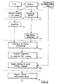
- FIG. 2 shows in block form the process of constructing the so called map.
- the engine is indicated at 10 and is supplied with fuel in timed relationship, by a fuel injection system indicated at 11.
- the engine is fitted with a radiation sensor 12 of the kind described in the aforesaid specification and the fuel injection nozzle of the combustion space with which the radiation sensor is associated, is fitted with a needle lift sensor 13 which provides an indication of the lifting of the valve member of the nozzle from its seating and therefore the commencement of fuel delivery to the combustion space.
- the signals provided by the two sensors are amplified by amplifiers 14 and 15 respectively, the amplifier 14 being a logarithmic amplifier.
- the signals provided by the amplifiers are then subject to computer analysis, the first step of which is to convert the analog signals to digital signals in a converter 16 after which the aforesaid end of combustion point is determined by the use of a suitable algorithm. This process is illustrated as being carried out in the box 17.
- the engine exhaust is sampled at engine operating conditions both below and above full load, using a conventional smoke meter 19 and the information is supplied along with the end of combustion point to a processing stage 20 which fixes a point on the map.
- the engine is tested at various fuel levels and speeds in order to produce the map 18. Experiments have indicated that the level of smoke is also dependant upon the timing of fuel delivery to the engine and therefore the map produced will be "three dimensional".
- the concept of the invention can be used in vehicle engine installations in order to ensure that in the use of the vehicle no more than the permitted level of smoke occurs in the engine exhaust at all speeds of engine operation.
- the amount of fuel supplied to the engine will depend upon the demand placed on the engine by the driver of the vehicle. However, apart from the level of smoke in the engine exhaust there are other limits which may not be exceeded in the use of the vehicle for example, the engine speed.
- the fuel injection system of the engine will therefore be controlled by a governor which will at least control the idling speed and the maximum speed of the engine.
- testing is carried out in a test cell and it is not generally the practice to test each production engine together with its fuel system following assembly. However, each fuel system is set or calibrated in accordance with the test results obtained.
- a production engine will in most instances, be operated at slightly less than the maximum power. If, however, the actual smoke level in the engine exhaust during the operation of the engine can be assessed it is possible to operate the engine if so required by the driver, at its maximum smoke limited power.
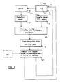
- FIG 3 there is shown a block diagram of a system for use with a production engine.
- the fuel injection system 21 includes a governor which is responsive to driver demand as represented by an input signal 22.
- the system is also supplied with two further input signals 23, 24, the signal 23 being a timing adjustment signal and the signal 24 being a fuel delivery quantity adjustment signal.
- the signals provided by the sensors 12 and 13 are supplied to an analog/digital convertor 25 which includes amplifiers, the amplifier associated with the sensor 12 being a logarithmic amplifier. From the digital signals derived from the sensor signals the end of combustion point is determined and hence the combustion period as measured from the instant of fuel delivery. The computation of the combustion period is indicated in the diagram at 26.
- the computed combustion period together with the engine speed and the start of combustion are then identified on the map 18 together with the timing of fuel delivery and if the smoke value thus obtained is greater than the allowed value, a calculation is effected to adjust the quantity of fuel supplied to the engine the timing of fuel delivery being adjusted having regard to the usual engine operating parameters.
- the comparison with the map 18 and the generation of the signals 23, 24 to adjust the timing and fuel delivery are effected in the stage 27.
Landscapes
- Engineering & Computer Science (AREA)
- Chemical & Material Sciences (AREA)
- Combustion & Propulsion (AREA)
- Mechanical Engineering (AREA)
- General Engineering & Computer Science (AREA)
- Electrical Control Of Air Or Fuel Supplied To Internal-Combustion Engine (AREA)
- Combined Controls Of Internal Combustion Engines (AREA)
- Investigating Or Analysing Materials By Optical Means (AREA)
Claims (3)
Applications Claiming Priority (2)
| Application Number | Priority Date | Filing Date | Title |
|---|---|---|---|
| GB888824962A GB8824962D0 (en) | 1988-10-25 | 1988-10-25 | Smoke measuring apparatus |
| GB8824962 | 1988-10-25 |
Publications (2)
| Publication Number | Publication Date |
|---|---|
| EP0370621A1 EP0370621A1 (de) | 1990-05-30 |
| EP0370621B1 true EP0370621B1 (de) | 1991-12-11 |
Family
ID=10645750
Family Applications (1)
| Application Number | Title | Priority Date | Filing Date |
|---|---|---|---|
| EP89310798A Expired EP0370621B1 (de) | 1988-10-25 | 1989-10-20 | Rauchmessgerät |
Country Status (5)
| Country | Link |
|---|---|
| US (1) | US4987772A (de) |
| EP (1) | EP0370621B1 (de) |
| DE (1) | DE68900541D1 (de) |
| ES (1) | ES2028442T3 (de) |
| GB (1) | GB8824962D0 (de) |
Families Citing this family (2)
| Publication number | Priority date | Publication date | Assignee | Title |
|---|---|---|---|---|
| US6389330B1 (en) | 1997-12-18 | 2002-05-14 | Reuter-Stokes, Inc. | Combustion diagnostics method and system |
| RU2184056C2 (ru) * | 2000-06-01 | 2002-06-27 | Автономная некоммерческая организация Саратовское конструкторское бюро тары и упаковки "Профипак" | Устройство для обжима алюминиевых колпачков |
Family Cites Families (3)
| Publication number | Priority date | Publication date | Assignee | Title |
|---|---|---|---|---|
| US4760830A (en) * | 1981-07-23 | 1988-08-02 | Ambac Industries, Incorporated | Method and apparatus for controlling fuel injection timing in a compression ignition engine |
| JPS60135647A (ja) * | 1983-12-22 | 1985-07-19 | Toyota Motor Corp | デイ−ゼルエンジンの燃料噴射装置 |
| JPH0684939B2 (ja) * | 1986-08-13 | 1994-10-26 | 株式会社日立製作所 | 空燃比検出式燃焼センサ |
-
1988
- 1988-10-25 GB GB888824962A patent/GB8824962D0/en active Pending
-
1989
- 1989-10-20 ES ES198989310798T patent/ES2028442T3/es not_active Expired - Lifetime
- 1989-10-20 DE DE8989310798T patent/DE68900541D1/de not_active Expired - Lifetime
- 1989-10-20 EP EP89310798A patent/EP0370621B1/de not_active Expired
- 1989-10-24 US US07/426,324 patent/US4987772A/en not_active Expired - Fee Related
Also Published As
| Publication number | Publication date |
|---|---|
| ES2028442T3 (es) | 1992-07-01 |
| US4987772A (en) | 1991-01-29 |
| EP0370621A1 (de) | 1990-05-30 |
| DE68900541D1 (de) | 1992-01-23 |
| GB8824962D0 (en) | 1988-11-30 |
Similar Documents
| Publication | Publication Date | Title |
|---|---|---|
| EP0115806A2 (de) | Steuersystem für Brennkraftmaschine | |
| US6243641B1 (en) | System and method for detecting engine cylinder misfire | |
| US6276319B2 (en) | Method for evaluating the march of pressure in a combustion chamber | |
| EP0282295B1 (de) | Regelung einer Brennkraftmaschine | |
| US4814997A (en) | Method and apparatus for estimating an atmospheric pressure based on an intact air pressure at a certain time | |
| US4531399A (en) | Method of calibrating pressure sensor | |
| US5862661A (en) | Method for monitoring catalytic converter efficiency | |
| US5353768A (en) | Fuel control system with compensation for intake valve and engine coolant temperature warm-up rates | |
| EP0115807B1 (de) | Verfahren zur Unterscheidung des Verbrennungsdruckes für eine Brennkraftmaschine | |
| JPH04283644A (ja) | 内燃機関による窒素酸化物の放出をモニタする方法 | |
| US5474052A (en) | Automated method for cold transient fuel compensation calibration | |
| EP0478120A2 (de) | Verfahren und Vorrichtung zur Ableitung des den Innenverbrennungsmotor umgebenden atmosphärischen Druckes | |
| EP0476811B1 (de) | Verfahren und Vorrichtung zum Steuern eines Verbrennungsmotors | |
| US6016796A (en) | Fuel blending ratio inferring method | |
| US5020360A (en) | Process for determining and evaluating the combustion pressure of an internal combustion engine | |
| US5592815A (en) | Process for monitoring the conversion rate of an exhaust catalyst | |
| US5631412A (en) | Apparatus and method for estimating atmospheric pressure in an internal combustion engine | |
| Head et al. | Noise of diesel engines under transient conditions | |
| US4497297A (en) | Control system for air/fuel ratio adjustment system | |
| US4987772A (en) | Smoke measuring apparatus | |
| CA1141993A (en) | Octane measuring | |
| KR100378480B1 (ko) | 직접분사식내연기관을제어하기위한방법 | |
| GB2301898A (en) | Detecting engine cylinder misfire | |
| US4495919A (en) | Control system for air/fuel ratio adjustment system | |
| GB2149535A (en) | Internal combustion engine fuel supply and tuning |
Legal Events
| Date | Code | Title | Description |
|---|---|---|---|
| PUAI | Public reference made under article 153(3) epc to a published international application that has entered the european phase |
Free format text: ORIGINAL CODE: 0009012 |
|
| AK | Designated contracting states |
Kind code of ref document: A1 Designated state(s): DE ES FR GB IT |
|
| 17P | Request for examination filed |
Effective date: 19900829 |
|
| 17Q | First examination report despatched |
Effective date: 19910204 |
|
| GRAA | (expected) grant |
Free format text: ORIGINAL CODE: 0009210 |
|
| AK | Designated contracting states |
Kind code of ref document: B1 Designated state(s): DE ES FR GB IT |
|
| ITF | It: translation for a ep patent filed | ||
| REF | Corresponds to: |
Ref document number: 68900541 Country of ref document: DE Date of ref document: 19920123 |
|
| ET | Fr: translation filed | ||
| REG | Reference to a national code |
Ref country code: ES Ref legal event code: FG2A Ref document number: 2028442 Country of ref document: ES Kind code of ref document: T3 |
|
| PLBE | No opposition filed within time limit |
Free format text: ORIGINAL CODE: 0009261 |
|
| STAA | Information on the status of an ep patent application or granted ep patent |
Free format text: STATUS: NO OPPOSITION FILED WITHIN TIME LIMIT |
|
| 26N | No opposition filed | ||
| PGFP | Annual fee paid to national office [announced via postgrant information from national office to epo] |
Ref country code: FR Payment date: 19971009 Year of fee payment: 9 |
|
| PGFP | Annual fee paid to national office [announced via postgrant information from national office to epo] |
Ref country code: GB Payment date: 19971013 Year of fee payment: 9 |
|
| PGFP | Annual fee paid to national office [announced via postgrant information from national office to epo] |
Ref country code: DE Payment date: 19971024 Year of fee payment: 9 |
|
| PGFP | Annual fee paid to national office [announced via postgrant information from national office to epo] |
Ref country code: ES Payment date: 19971031 Year of fee payment: 9 |
|
| PG25 | Lapsed in a contracting state [announced via postgrant information from national office to epo] |
Ref country code: GB Free format text: LAPSE BECAUSE OF NON-PAYMENT OF DUE FEES Effective date: 19981020 |
|
| PG25 | Lapsed in a contracting state [announced via postgrant information from national office to epo] |
Ref country code: ES Free format text: LAPSE BECAUSE OF THE APPLICANT RENOUNCES Effective date: 19981021 |
|
| GBPC | Gb: european patent ceased through non-payment of renewal fee |
Effective date: 19981020 |
|
| PG25 | Lapsed in a contracting state [announced via postgrant information from national office to epo] |
Ref country code: FR Free format text: LAPSE BECAUSE OF NON-PAYMENT OF DUE FEES Effective date: 19990630 |
|
| REG | Reference to a national code |
Ref country code: FR Ref legal event code: ST |
|
| PG25 | Lapsed in a contracting state [announced via postgrant information from national office to epo] |
Ref country code: DE Free format text: LAPSE BECAUSE OF NON-PAYMENT OF DUE FEES Effective date: 19990803 |
|
| REG | Reference to a national code |
Ref country code: ES Ref legal event code: FD2A Effective date: 20001102 |
|
| PG25 | Lapsed in a contracting state [announced via postgrant information from national office to epo] |
Ref country code: IT Free format text: LAPSE BECAUSE OF NON-PAYMENT OF DUE FEES;WARNING: LAPSES OF ITALIAN PATENTS WITH EFFECTIVE DATE BEFORE 2007 MAY HAVE OCCURRED AT ANY TIME BEFORE 2007. THE CORRECT EFFECTIVE DATE MAY BE DIFFERENT FROM THE ONE RECORDED. Effective date: 20051020 |