EP0370641A1 - Raccord de tuyau - Google Patents
Raccord de tuyau Download PDFInfo
- Publication number
- EP0370641A1 EP0370641A1 EP89311210A EP89311210A EP0370641A1 EP 0370641 A1 EP0370641 A1 EP 0370641A1 EP 89311210 A EP89311210 A EP 89311210A EP 89311210 A EP89311210 A EP 89311210A EP 0370641 A1 EP0370641 A1 EP 0370641A1
- Authority
- EP
- European Patent Office
- Prior art keywords
- thread
- pipe
- screw
- threads
- internal
- Prior art date
- Legal status (The legal status is an assumption and is not a legal conclusion. Google has not performed a legal analysis and makes no representation as to the accuracy of the status listed.)
- Granted
Links
- 239000012530 fluid Substances 0.000 claims abstract description 39
- 238000007789 sealing Methods 0.000 claims abstract description 28
- 230000004323 axial length Effects 0.000 claims abstract description 11
- 230000013011 mating Effects 0.000 abstract 1
- 230000008878 coupling Effects 0.000 description 5
- 238000010168 coupling process Methods 0.000 description 5
- 238000005859 coupling reaction Methods 0.000 description 5
- 150000001875 compounds Chemical class 0.000 description 4
- 239000000463 material Substances 0.000 description 2
- 206010052804 Drug tolerance Diseases 0.000 description 1
- 239000010419 fine particle Substances 0.000 description 1
- 238000004519 manufacturing process Methods 0.000 description 1
- 230000035515 penetration Effects 0.000 description 1
- 238000010008 shearing Methods 0.000 description 1
Images


Classifications
-
- F—MECHANICAL ENGINEERING; LIGHTING; HEATING; WEAPONS; BLASTING
- F16—ENGINEERING ELEMENTS AND UNITS; GENERAL MEASURES FOR PRODUCING AND MAINTAINING EFFECTIVE FUNCTIONING OF MACHINES OR INSTALLATIONS; THERMAL INSULATION IN GENERAL
- F16B—DEVICES FOR FASTENING OR SECURING CONSTRUCTIONAL ELEMENTS OR MACHINE PARTS TOGETHER, e.g. NAILS, BOLTS, CIRCLIPS, CLAMPS, CLIPS OR WEDGES; JOINTS OR JOINTING
- F16B33/00—Features common to bolt and nut
- F16B33/02—Shape of thread; Special thread-forms
-
- F—MECHANICAL ENGINEERING; LIGHTING; HEATING; WEAPONS; BLASTING
- F16—ENGINEERING ELEMENTS AND UNITS; GENERAL MEASURES FOR PRODUCING AND MAINTAINING EFFECTIVE FUNCTIONING OF MACHINES OR INSTALLATIONS; THERMAL INSULATION IN GENERAL
- F16L—PIPES; JOINTS OR FITTINGS FOR PIPES; SUPPORTS FOR PIPES, CABLES OR PROTECTIVE TUBING; MEANS FOR THERMAL INSULATION IN GENERAL
- F16L41/00—Branching pipes; Joining pipes to walls
- F16L41/007—Branching pipes; Joining pipes to walls adjustable and comprising a bend
Definitions
- This invention relates to pipe joints to be screwed into pipe-connecting threads provided in various types of pressurized fluid apparatuses.
- Pipe-connecting threads are cut in ports through which pressurized fluids are fed into and discharged from directional and other types of valves, piston cylinders and other fluid apparatuses.
- the tapered pipe threads R, Rc, Rp and the tapered threads NPT for U.S. standard pipes are designed to secure leak tightness by bringing the faces of meshed external and internal threads into contact under pressure. Actually, however, some gap can be left between the crest of the external thread and the root of the internal thread or between the root of the external thread and the crest of the internal thread depending on their dimensional tolerances, which can sometimes, lead to the leakage of fluids. Therefore, sealing tape or sealing compound is applied on the external threads to secure the desired tightness.
- the parallel pipe threads G are commonly used with separate sealing members.
- FIG. 6 Two pipe joints illustrated in Fig. 6 show that the length of engagement between a tapered thread 3 cut on a pipe joint 1 and a fluid apparatus 2 can vary if the dimensional tolerance of the thread and the position of gauge plane on the thread-cutting machine vary. Variation in the engaging length also occurs when the fitting is tightened with different number of turns. For this reason, conventional tapered threads have been cut over longer length than is otherwise required in order to secure the desired tightness. This longer thread design has resulted in higher production cost, increased fitting difficulty in narrow spaces and more screwing man-hours.
- tapered pipe threads usually tend to become over-tightened beyond the position of gauge planes where the diameters of the meshed external and internal threads coincides.
- a primary object of this invention is to provide a pipe joint for apparatuses processing fluids, controlling the flow of fluids or actuated by the pressure of fluids which is adapted to closely fit any of pipe threads of different types having the same nominal diameter.
- Another object of this invention is to provide a pipe joint of simple structure adapted to fit pipe threads of different types having the same nominal diameter by securing mechanical connection with the thread cut thereon and tightness by means of a sealing member.
- Still another object of this invention is to provide sealing means that assures easy and effective sealing with the pipe joints of the type described above that are adapted to fit pipe threads of different types having the same nominal diameter.
- a pipe joint of this invention comprises a screw-in portion, an external thread being cut on the outer surface of the screw-in portion having a thread profile which can mesh with the innermost among the thread profiles which are different types of internal pipe threads of the same nominal diameter, axially aligned with the gauge planes thereof positioned at the same point; the axial length of the external thread being reduced to a minimum within the limit that the desired firm mechanical connection is secured; a contact surface being provided at the base end of the screw-in portion which comes in contact with the surface of the fluid apparatus when the external thread is screwed into the fluid apparatus; a groove being provided next to the contact surface; and a sealing member to seal between the screw-in portion and the fluid apparatus being fit in the groove.
- a pipe joint of this invention comprises a screw-in portion, an internal thread being cut on the inner surface of the screw-in portion having a thread profile which can mesh with the outermost among the thread profiles which are different types of external pipe threads of the same nominal diameter, axially aligned with the gauge planes thereof positioned at the same point; the axial length of the internal thread being reduced to a minimum within the limit that the desired firm mechanical connection is secured; a sealing member being provided between the base end of the internal thread and the foremost end of the pipe thread provided on the fluid apparatus.
- a pipe joint comprising as described above can mesh with different types of pipe threads having the same nominal diameter on a fluid apparatus because the external or internal thread profile of the screw-in portion can mesh with the innermost or outermost thread of the same nominal diameter as described hereinbefore.
- sealing member to provide a non-leaking union between the fluid apparatus and threaded portion eliminates the need to provide a sealing function to the thread, thereby permitting to reduce the axial length of the thread to a minimum.
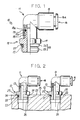
- FIG. 1 shows a first preferred embodiment of this invention, which has a multi-fittable external thread that can be screwed into different types of internal threads having a same nominal diameter cut in valves, pneumatic cylinders and other fluid apparatuses.
- a pipe joint 10 comprises a joint proper 11, a driving half coupling 12 rotatably, but not axially slidably, attached to the joint proper 11, and a sealing O-ring 13 provided between the joint proper 11 and the driving half coupling 12.
- the joint proper 11 is an elbow with a one-touch fitting 16 that comprises a tube connecting casing 15 at the opposite end of the driving half coupling 12, a sealing compound and an engaging portion biting into the outer wall of a tube to be connected (both being not shown), and a release member 16a that releases the engaging portion and, as a consequence, the engaged tube when pushed into the tube connecting casing 15.
- the one- touch fitting 16 is of the type, for example, described in Japanese Utility Model Publication No. 4796-1986. But the pipe joints according to this invention are not limited to elbows; any design will do so long as it permits connection of tube to the joint proper 11.
- the driving half coupling 12 comprises a press-in portion 18 that is pressed into an opening of the joint proper 11, with a groove 18a to accommodate the O-ring 13 and a projection 18b that prevents the slip-off the driving half coupling 12 from the joint proper 11, while allowing the rotation thereof, by the engagement of the edge thereof with a groove cut in the inner wall of the joint proper 11, a hexagonal nut-like projection 19 for engagement with a wrench or other turning tool in the middle, and a screw-in portion 20 at the opposite end of the press-in portion.
- a contact surface 21 that is pressed against the surface of the fluid apparatus when the screw-in portion 20 is screwed into a pipe thread cut therein.
- a sealing member 24 to provide a non-leaking union between the fluid apparatus and screw-in portion is fitted in a groove 22 provided next to the contact surface 21.
- a multi-fittable external thread 23 to be described in the following is cut on the outside surface of the screw-in portion to mesh with the internal pipe thread cut in the fluid apparatus.
- the axial length of the external thread 23 can be reduced to a minimum within the limit that firm enough connection to withstand the pressure of the transported fluid is secured.
- the external thread is usually 2 to 4 ribs long. Being very short when compared with the pipe threads provided on fluid apparatuses, the axial length of the external thread 23 by no means offers inconvenience to fitting.
- Fig. 3 shows a multi-fittable thread that meshes with any of the tapered internal pipe thread Rc, parallel internal thread G, tapered internal thread for U.S. standard pipes NPT and tight tapered internal thread for U.S. standard pipes NPTF.
- a solid line, thick solid line, a dotted line, a dot-dash line and a fine solid line respectively show the standard internal threads Rc, G, NPT and NPTF of the same nominal diameter axially overlapped so that their positions of gauge plane are coincided at the same point.
- ⁇ designates an angle slightly greater than 1/2 of the taper angle of the tapered threads.
- Dimensional tolerances of the individual threads are specified in their standards.
- the profile of the multi-fittable external thread 6 suitable for use with any of the four types of commonly used internal pipe threads must be on the inside of the profiles of the internal threads.
- the internal threads Rc and G are identical in the gauge diameter, thread pitch, the angle of thread, and the roundness of thread crest and rood. Their difference lies in only one point; while the internal thread G is of the parallel type, the internal thread g is tapered, with its diameter narrowing down in the screwing direction. Therefore, the profile of the internal thread G is always on the inside of the profiles of the internal thread Rc.
- the internal threads NPT and NPTF are identical in pitch angle, taper angle, the angle and height of crest, and effective diameter. Although their major and minor diameters, the minimum major diameter of the internal thread NPTF is smaller than that of the internal thread NPT and larger than that of the internal thread Rc.
- the minimum minor diameter of the internal thread NPT is very slightly smaller than that of the internal thread NPTF. Therefore, the external thread 6 meshes with the internal thread NPTF if it is designed with the minimum minor diameter of the internal thread NPT in mind.
- the profile of the external thread 6 must be on the inside of the profiles of the internal threads Rc and NPT.
- Triangles defined by the contours of the threads Rc and NPT form a continuous helical rib having a geometrically determined pitch and taper angle. Therefore, the profile, including the height of the crest and the depth of the root, of a multi-fittable external thread suitable for use with the internal threads Rc, G, NPT and NPTF can be designed on the basis of the pitch, taper angle, the angle and height of crest and other parameters thus determined, with the diameter and dimensional tolerances of the standard profiles of the internal threads in mind.
- the hatched portion in Fig. 3 shows an example of the profile of an external thread thus determined.
- the external thread 6 may then take any desired profile so long as it lies on the inside of the profiles of the internal threads Rc and NPT.
- the pipe fitting described above is used as shown in Fig. 2, with the external thread 23 on the screw-in portion 20 screwed into a pipe thread 26 cut in a fluid apparatus 25 and the tube connecting case 15 connected to a tube not shown.
- the sealing member 24 fitted in the groove 22 becomes tightened between the groove 22 and a chamfered surface 28 around the periphery of the pipe thread 26, thereby providing a non-leaking union therebetween.
- the pipe joint just described can be screwed into any of the different types of pipe threads so long as their nominal diameter is the same. This eliminates the need to stock different types of pipe joints of the same diameter, which, in turn, reduces the stock control cost burden on both makers and users and prevents troubles resulting from misuse.
- the sealing member 24 fitted in the groove 22 and tightened between the groove and the chamfered surface 28 of the pipe thread 26 provides the desired sealing independently of the screw-in portion.
- the screw-in portion assures the desired mechanical connection independently of the sealing member providing a non-leaking union.
- the axial length of the external thread 23 can be reduced to a minimum, generally 2 to 4 ribs long, so long as strong enough connection to withstand the pressure of the transported fluid is secured. This saves material and working costs, permits fitting in conventionally inaccessible narrow spaces, reduces screw-in manhours, and eliminates the trouble of sealing compound application.
- the contact surface 21 serves as a stopper to limit the further penetration of the external thread 23 into the fluid apparatus 25. This substantially eliminates the possibility of generating a compressive force to cause the sticking of thread faces and breaking thread ribs.
- Fig. 4 shows a second preferred embodiment of this invention having a multi-fittable internal thread suitable for use with external threads on a fluid apparatus.
- This pipe joint 30 comprises a joint proper 31 which, in turn, comprises a tube connecting portion 37 equipped with a one-touch fitting 16 of the type identical to the one used with the first preferred embodiment described before.
- a multi-fittable internal thread 33 to mesh with an external pipe thread 41 on a tube 40 attached to the fluid apparatus is cut on the inner surface of a screw-in portion 32, with a sealing member 34 provided between the base end thereof and the foremost end of the external thread 41.
- the pipe joint 30 is attached to a stationary member 38 by inserting the tube connection portion 37 into a receiving hole 38a, with the shoulder of the screw-in portion 32 positioned against the stationary member 38 and a nut 35 screwed onto the external thread cut on the outer surface of the tube connection portion 37.
- the multi-fittable internal thread 33 on the screw-in portion 32 of this second preferred embodiment meshes with any of the external threads R, G, NPT and NPTF of the same nominal diameter.
- the profile of this internal thread can be designed in the same way as done with the external thread described previously by reference to Fig. 3, except that the profiles represented by reference numeral 5 must be considered as those of external threads and the profiles represented by numeral 6 as those of internal threads. In addition, the profile of the internal thread must be on the outside of the profile of the external thread.
- Fig. 5 is a view similar to Fig. 3, in which an example of the profile of the multi-fittable internal thread 33 is shown, with reference numerals 45 and 46 respectively designating an internal and an external thread.
Landscapes
- Engineering & Computer Science (AREA)
- General Engineering & Computer Science (AREA)
- Mechanical Engineering (AREA)
- Non-Disconnectible Joints And Screw-Threaded Joints (AREA)
- Joints With Pressure Members (AREA)
Applications Claiming Priority (2)
| Application Number | Priority Date | Filing Date | Title |
|---|---|---|---|
| JP276987/88 | 1988-11-01 | ||
| JP63276987A JPH0686916B2 (ja) | 1988-11-01 | 1988-11-01 | 管継手 |
Publications (2)
| Publication Number | Publication Date |
|---|---|
| EP0370641A1 true EP0370641A1 (fr) | 1990-05-30 |
| EP0370641B1 EP0370641B1 (fr) | 1994-10-12 |
Family
ID=17577190
Family Applications (1)
| Application Number | Title | Priority Date | Filing Date |
|---|---|---|---|
| EP89311210A Expired - Lifetime EP0370641B1 (fr) | 1988-11-01 | 1989-10-31 | Raccord de tuyau |
Country Status (4)
| Country | Link |
|---|---|
| US (1) | US5165731A (fr) |
| EP (1) | EP0370641B1 (fr) |
| JP (1) | JPH0686916B2 (fr) |
| DE (1) | DE68918801T2 (fr) |
Cited By (5)
| Publication number | Priority date | Publication date | Assignee | Title |
|---|---|---|---|---|
| EP0482204A4 (en) * | 1990-04-16 | 1992-09-09 | Smc Corporation | Pipe joint |
| FR2676109A1 (fr) * | 1991-04-09 | 1992-11-06 | Festo Kg | Filetage exterieur et filetage interieur, de preference pour la realisation de raccords pour fluides en pneumatique. |
| EP0751328A1 (fr) * | 1995-06-29 | 1997-01-02 | John Derek Guest | Raccords à vis |
| EP0957306A3 (fr) * | 1998-05-13 | 2000-07-19 | Smc Kabushiki Kaisha | Raccord de tuyaux et outillage pour la manufacture de celui-ci |
| US20220090364A1 (en) * | 2019-01-22 | 2022-03-24 | Oblamatik Ag | Fitting connecting piece |
Families Citing this family (14)
| Publication number | Priority date | Publication date | Assignee | Title |
|---|---|---|---|---|
| DE29721200U1 (de) * | 1997-11-29 | 1998-01-22 | Bümach Engineering International B.V., Emmen | Dichtende Gewindepaarung |
| US6045166A (en) * | 1998-07-31 | 2000-04-04 | The Rexroth Corporation | High pressure plug/port assembly |
| US6113154A (en) * | 1998-09-15 | 2000-09-05 | Thut; Bruno H. | Immersion heat exchangers |
| JP3561440B2 (ja) | 1999-07-01 | 2004-09-02 | Smc株式会社 | 管継手 |
| EP1279880B1 (fr) * | 2001-07-24 | 2005-02-02 | Olab S.r.l. | Système d'étanchéité comportant un joint d'étanchéité |
| USD524149S1 (en) * | 2005-02-02 | 2006-07-04 | Bong-Uk Kim | Ball joint |
| USD597636S1 (en) * | 2007-09-26 | 2009-08-04 | Yuk Nam Choi | Fitting |
| JP2010185568A (ja) * | 2009-01-14 | 2010-08-26 | Smc Corp | 管継手 |
| CN105485140B (zh) * | 2016-01-18 | 2018-03-06 | 东莞市贯虹五金科技有限公司 | 一种r型螺纹 |
| CN106065977A (zh) * | 2016-08-06 | 2016-11-02 | 谢秋鸿 | 一种流体结构的密封装置 |
| CN106439332B (zh) * | 2016-12-21 | 2018-11-09 | 中国南方航空工业(集团)有限公司 | 旋转管接头 |
| US10815988B2 (en) * | 2017-04-18 | 2020-10-27 | St9 Gas And Oil, Llc | Frac pump sealed nut assembly |
| CN108730649B (zh) * | 2018-04-11 | 2019-11-29 | 宁波亚德客自动化工业有限公司 | 一种两段式管螺纹密封结构 |
| US10711876B1 (en) * | 2019-10-28 | 2020-07-14 | Saptfc Holding, Llc | Reinforcement sealing tubes for stabilizing a housing in an automobile transmission |
Citations (4)
| Publication number | Priority date | Publication date | Assignee | Title |
|---|---|---|---|---|
| DE1027014B (de) * | 1952-11-21 | 1958-03-27 | Neosid Pemetzrieder G M B H | In ein Muttergewinde eindrehbarer Schraubkern aus ferromagnetischer Masse oder Ferrit |
| US3323402A (en) * | 1965-10-08 | 1967-06-06 | Standard Pressed Steel Co | Thread forms |
| US3376053A (en) * | 1964-08-13 | 1968-04-02 | Rosan Eng Corp | Rotatable high pressure fluid fitting |
| EP0091844A1 (fr) * | 1982-04-08 | 1983-10-19 | Legris-Société Anonyme dite | Joint d'étanchéité disposé entre un appareil et un raccord vissé pour tuyauterie de fluide à haute pression |
Family Cites Families (9)
| Publication number | Priority date | Publication date | Assignee | Title |
|---|---|---|---|---|
| US1226921A (en) * | 1912-07-02 | 1917-05-22 | Crouse Hinds Co | Connection for electric conduits. |
| US1992793A (en) * | 1933-05-04 | 1935-02-26 | Bigelow Company | Water tube box closure |
| US2187217A (en) * | 1938-06-29 | 1940-01-16 | American Hard Rubber Co | Pipe joint |
| US2342425A (en) * | 1941-03-31 | 1944-02-22 | Parker Appliance Co | Pipe coupling |
| US2553340A (en) * | 1947-10-22 | 1951-05-15 | Theodore C Smith | Seal for auxiliary filling nipples |
| US3074748A (en) * | 1961-03-24 | 1963-01-22 | Ulrich Foundation Inc | Threaded pipe connection |
| US3173712A (en) * | 1961-04-13 | 1965-03-16 | Crawford Fitting Co | O-ring or gasket seal, tapered pipe thread male connector |
| CH640617A5 (de) * | 1979-07-06 | 1984-01-13 | Baumgartner Merzia | Verbindungselement zum einschrauben in eine leitung oder in einen apparat zum anschluss an das leitungssystem des druckmediumkreislaufes. |
| JPS62176580U (fr) * | 1986-04-28 | 1987-11-10 |
-
1988
- 1988-11-01 JP JP63276987A patent/JPH0686916B2/ja not_active Expired - Lifetime
-
1989
- 1989-10-31 DE DE68918801T patent/DE68918801T2/de not_active Expired - Lifetime
- 1989-10-31 EP EP89311210A patent/EP0370641B1/fr not_active Expired - Lifetime
- 1989-11-01 US US07/430,584 patent/US5165731A/en not_active Expired - Lifetime
Patent Citations (4)
| Publication number | Priority date | Publication date | Assignee | Title |
|---|---|---|---|---|
| DE1027014B (de) * | 1952-11-21 | 1958-03-27 | Neosid Pemetzrieder G M B H | In ein Muttergewinde eindrehbarer Schraubkern aus ferromagnetischer Masse oder Ferrit |
| US3376053A (en) * | 1964-08-13 | 1968-04-02 | Rosan Eng Corp | Rotatable high pressure fluid fitting |
| US3323402A (en) * | 1965-10-08 | 1967-06-06 | Standard Pressed Steel Co | Thread forms |
| EP0091844A1 (fr) * | 1982-04-08 | 1983-10-19 | Legris-Société Anonyme dite | Joint d'étanchéité disposé entre un appareil et un raccord vissé pour tuyauterie de fluide à haute pression |
Cited By (15)
| Publication number | Priority date | Publication date | Assignee | Title |
|---|---|---|---|---|
| EP0482204A4 (en) * | 1990-04-16 | 1992-09-09 | Smc Corporation | Pipe joint |
| US5433489A (en) * | 1990-04-16 | 1995-07-18 | Smc Corporation | Pipe fitting |
| FR2676109A1 (fr) * | 1991-04-09 | 1992-11-06 | Festo Kg | Filetage exterieur et filetage interieur, de preference pour la realisation de raccords pour fluides en pneumatique. |
| US5221113A (en) * | 1991-04-09 | 1993-06-22 | Festo K.G. | Male and female screw threads, more especially for pneumatic equipment |
| EP0751328A1 (fr) * | 1995-06-29 | 1997-01-02 | John Derek Guest | Raccords à vis |
| US6415488B1 (en) | 1998-05-13 | 2002-07-09 | Smc Kabushiki Kaisha | Tube joint and apparatus for producing the same |
| EP0957306A3 (fr) * | 1998-05-13 | 2000-07-19 | Smc Kabushiki Kaisha | Raccord de tuyaux et outillage pour la manufacture de celui-ci |
| EP1250970A3 (fr) * | 1998-05-13 | 2002-10-30 | Smc Kabushiki Kaisha | Raccord de tuyau en résine avec un anneau de renforcement |
| US6578879B2 (en) | 1998-05-13 | 2003-06-17 | Smc Kabushiki Kaisha | Tube joint with connecting member and guide member configured to be prevented from disengagement |
| EP1443252A3 (fr) * | 1998-05-13 | 2004-08-11 | Smc Kabushiki Kaisha | Raccord de tuyaux |
| US6880864B2 (en) | 1998-05-13 | 2005-04-19 | Smc Kabushiki Kaisha | Tube joint with attachment and detachment mechanism |
| US7093862B2 (en) | 1998-05-13 | 2006-08-22 | Smc Kabushiki Kaisha | Tube joint and apparatus for producing the same |
| EP1688197A3 (fr) * | 1998-05-13 | 2006-08-23 | SMC Kabushiki Kaisha | Raccord de tuyau en résine avec un anneau de renforcement |
| US7210708B2 (en) | 1998-05-13 | 2007-05-01 | Smc Kabushiki Kaisha | Tube joint |
| US20220090364A1 (en) * | 2019-01-22 | 2022-03-24 | Oblamatik Ag | Fitting connecting piece |
Also Published As
| Publication number | Publication date |
|---|---|
| EP0370641B1 (fr) | 1994-10-12 |
| US5165731A (en) | 1992-11-24 |
| JPH0686916B2 (ja) | 1994-11-02 |
| JPH02229986A (ja) | 1990-09-12 |
| DE68918801D1 (de) | 1994-11-17 |
| DE68918801T2 (de) | 1995-02-09 |
Similar Documents
| Publication | Publication Date | Title |
|---|---|---|
| US5165731A (en) | Pipe fitting having a multi-fittable thread | |
| EP0482204B1 (fr) | Raccord de tuyaux | |
| US4397485A (en) | Threadless pipe fitting | |
| US7032934B2 (en) | Hydraulic fitting | |
| US4154466A (en) | Pipe section and coupling | |
| US3092404A (en) | Packed screw threaded gland type tube coupling for thin walled tubing | |
| US4458926A (en) | Hydraulic hose adapter with O-ring seal | |
| CA1317611C (fr) | Dispositif d'etancheite pour adaptateur | |
| US4252346A (en) | Connection for transition from a cutting ring joint or similar to a flange joint | |
| US5135269A (en) | Tube coupling | |
| US4805944A (en) | Beaded tube coupling with end seal ring | |
| US5110160A (en) | High pressure port fitting system | |
| EP1337779B1 (fr) | Joint de tuyaux reduisant la force de serrage requise, y compris ecrou de serrage a deux sections filetees aux pas differents | |
| GB2274693A (en) | Pipe connector | |
| US11143339B2 (en) | Coupling for fluid conduits | |
| CA2079843A1 (fr) | Raccord de tuyauterie | |
| US3863958A (en) | Universal hose coupling | |
| US3630548A (en) | Hose-fitting system | |
| US5076616A (en) | Hydraulic fitting with O-ring seal end stop | |
| USRE31123E (en) | Pipe section and coupling | |
| US4610466A (en) | Convertible flare/braze fitting | |
| GB2197410A (en) | Pipe coupling | |
| US2971780A (en) | Porthole tube fitting having selfaligned coined fluid seat | |
| GB2234306A (en) | Pipe fittings | |
| EP0751328A1 (fr) | Raccords à vis |
Legal Events
| Date | Code | Title | Description |
|---|---|---|---|
| PUAI | Public reference made under article 153(3) epc to a published international application that has entered the european phase |
Free format text: ORIGINAL CODE: 0009012 |
|
| 17P | Request for examination filed |
Effective date: 19891110 |
|
| AK | Designated contracting states |
Kind code of ref document: A1 Designated state(s): DE FR GB IT |
|
| 17Q | First examination report despatched |
Effective date: 19910125 |
|
| GRAA | (expected) grant |
Free format text: ORIGINAL CODE: 0009210 |
|
| AK | Designated contracting states |
Kind code of ref document: B1 Designated state(s): DE FR GB IT |
|
| ITF | It: translation for a ep patent filed | ||
| REF | Corresponds to: |
Ref document number: 68918801 Country of ref document: DE Date of ref document: 19941117 |
|
| ET | Fr: translation filed | ||
| PLBE | No opposition filed within time limit |
Free format text: ORIGINAL CODE: 0009261 |
|
| STAA | Information on the status of an ep patent application or granted ep patent |
Free format text: STATUS: NO OPPOSITION FILED WITHIN TIME LIMIT |
|
| 26N | No opposition filed | ||
| REG | Reference to a national code |
Ref country code: GB Ref legal event code: IF02 |
|
| PGFP | Annual fee paid to national office [announced via postgrant information from national office to epo] |
Ref country code: DE Payment date: 20081022 Year of fee payment: 20 |
|
| PGFP | Annual fee paid to national office [announced via postgrant information from national office to epo] |
Ref country code: IT Payment date: 20081025 Year of fee payment: 20 |
|
| PGFP | Annual fee paid to national office [announced via postgrant information from national office to epo] |
Ref country code: FR Payment date: 20081014 Year of fee payment: 20 |
|
| PGFP | Annual fee paid to national office [announced via postgrant information from national office to epo] |
Ref country code: GB Payment date: 20081021 Year of fee payment: 20 |
|
| REG | Reference to a national code |
Ref country code: GB Ref legal event code: PE20 Expiry date: 20091030 |
|
| PG25 | Lapsed in a contracting state [announced via postgrant information from national office to epo] |
Ref country code: GB Free format text: LAPSE BECAUSE OF EXPIRATION OF PROTECTION Effective date: 20091030 |